Table of Contents

Related Manuals for BPC Airflow DV145 Adroit


Summary of Contents for BPC Airflow DV145 Adroit
- Page 1 80000484 - Issue 1 04/16 Valid from 01/05/16 Instruction Manual DV145 Adroit DV110 Adroit DV96 Adroit 90000580 90000578 90000576 90000580EPH 90000578EPH 90000576EPH 90000581 90000579 90000577 90000581EPH 90000579EPH 90000577EPH...
-
Page 3: Table Of Contents
CONTENTS 1. INTRODUCTION • The main parts of the ventilation unit • System description • General safety Instructions, guarantee and liability • Control panel buttons • Starting up and shutting down the unit 2. DEPLOYMENT WIZARD • Basic settings (setting the language, time and date) •... - Page 5 ,1752'8&7,21 6<67(0 '(6&5,37,21...
- Page 6 INTRODUCTION DIFFERENCES BETWEEN THE UNITS Power • Size • DV96 can be equipped with an optional electric post heater. • DV110 and DV145 can be equipped with either one or two optional electric post heaters. Weight • In the model DV96, there is a sealing tape at the bottom of the •...
- Page 7 ,1752'8&7,21 ,167$//$7,21 Installation and setup should only be carried out by qualified experts. Electrical installations and connections must only be carried out by electricians, and according to the local regulations. &21752/ 3$1(/ %877216 %87721 '(6&5,37,21 &KDQJH SURILOH button. This button allows you to change the ventilation profile of the device.
- Page 8 ,1752'8&7,21 INTRODUCTION Ventilation has to be constant for the indoor air to stay healthy for the dwellers and the structures of the dwelling. Even for longer holidays, it is not advisable to stop the ventilation, because the indoor air will become stuffy and, during the heating season, the indoor air humidity may condense in the ventilation ductwork and structures, causing moisture damage.
- Page 9 INTRODUCTION The ventilation specialist has made the ventilation system with basic and expert settings, based on the ventilation plan. The basic settings are: • User interface language. • Time and date. The expert settings are: • System administrator password. The installer has given you the system administrator password.
-
Page 10: Basic Settings (Setting The Language, Time And Date)
%$6,& 6(77,1*6 '(3/2<0(17 :,=$5' 1. Start the ventilation device. 2. Press the 2. button. 3. The deployment wizard is launched. 6(/(&7,1* 7+( /$1*8$*( Select the user interface language as follows: 1. Use the arrow buttons to select the language you want, for example, English: 2. -
Page 11: Deployment Wizard
BASIC SETTINGS SET THE AUTOMATIC DAYLIGHT SAVING TIME By default, the system automatically switches to the summer time. If you want to use the automatic daylight saving time, proceed to the next step by pressing the right arrow button. If you want to use the manual daylight saving time, proceed as follows: 1. - Page 12 EXPERT SETTINGS PASSWORD AND ACCESS LEVEL Once you have finished up making the basic settings, the deployment wizard moves on to setting the system password. NOTE If you set the password as 0000, the password inquiry is not used. 1. The deployment wizard Password and access level screen is opened.
- Page 13 EXPERT SETTINGS FAN SETTINGS In the following chapters, you will set the output ratio between the WARNING supply and extract air fans. The ventilation specialist has made the supply and exhaust air settings when deploying the IMPORTANT ventilation unit. If you make changes to the settings, ensure Adjust the air flows, according to the values in the ventilation plan.
- Page 14 EXPERT SETTINGS PROFILE SETTINGS In the following chapters, you can make ventilation settings for the system profiles. HOME PROFILE When you want to make the At home profile settings, proceed as follows: The deployment wizard Home screen will open. NOTE Once you have set the basic ventilation air flow rates, the higher percentage value will default to the At home profile fan speed value.
- Page 15 EXPERT SETTINGS AWAY PROFILE When you want to make the Away profile settings, proceed as follows: 1. The deployment wizard Away profile screen is opened. NOTE Once you have set the fan speed for the At home profile, the fan speed for the Away profile will default to -30% of the At home profile fan speed.
- Page 16 EXPERT SETTINGS BOOST PROFILE When you want to make the Boost profile settings, proceed as follows: The deployment wizard Boost profile screen is opened. NOTE Once you have set the fan speed for the At home profile, the fan speed for the Boost profile will default to +30% of the At home profile fan speed.
- Page 17 EXPERT SETTINGS FIREPLACE PROFILE When you want to make the Fireplace function settings, proceed as follows: 1. The deployment wizard Fireplace function profile screen is opened. 2. Set the profile timer duration in minutes by using the Plus and Minus buttons. 3.
- Page 18 EXPERT SETTINGS FINISHING UP When you have completed the wizard, the Setup done! screen will open. Finish up the deployment, as follows: 1. If you want to go back to repair or change a value, use the arrow buttons to select the desired line and press the OK button.
-
Page 19: Ventilation Profiles
VENTILATION PROFILES THE VENTILATION UNIT HAS FOUR VENTILATION PROFILES: AT HOME AWAY BOOST FIREPLACE FUNCTION Use this Use this ventilation Use this profile when ventilation profile profile when the there are a lot of people Use this ventilation profile when the dwelling or premises in the apartment or on when, for example, you are... - Page 20 VENTILATION PROFILES CHANGING THE PROFILE If you want to change the ventilation profile, proceed as follows: 1. Press the Change profile button until the desired ventilation profile icon is displayed in the screen. 2. Wait until the ventilation profile main screen is displayed. 3.
- Page 21 VENTILATION PROFILES VIEWING THE AWAY PROFILE INFORMATION If you want to view the Away profile settings, proceed as follows: 1. Open the Away profile main view. 2. Press the Profile information button. 3. The first information screen for the profile appears.
- Page 22 VENTILATION PROFILES VIEWING THE BOOST PROFILE INFORMATION If you want to view the Boost profile settings, proceed as follows: 1. Open the Boost profile main view. 2. Press the Profile information button. 3. The first information screen for the profile is opened.
- Page 23 VENTILATION PROFILES 4. The first information screen for the profile appears. This screen contains the following information: Duration — This value indicates the enhanced ventilation duration when the Fireplace function is activated. The value is expressed in hours and minutes. Supply fan speed —...
- Page 24 VENTILATION PROFILES MODIFYING THE AWAY PROFILE SETTINGS Open the Away profile main view. Press the Profile information button. Press the Edit button. The fan speed setup screen is opened. Set the Away profile fan speed as a percentage of the maximum by using the Plus and Minus buttons.
- Page 25 VENTILATION PROFILES MODIFYING THE BOOST PROFILE SETTINGS When you want to edit the Boost profile settings, proceed as follows: Open Boost profile main view. Press the Profile information button. Press the Edit button. The fan speed setup screen is opened. Set the Boost profile fan speed as a percentage of the maximum by using the Plus and Minus buttons.
- Page 26 VENTILATION PROFILES MODIFYING THE FIREPLACE FUNCTION SETTINGS When you want to edit the Fireplace function settings, proceed as follows: 1. Open the Fireplace function main view. 2. Press the Profile information button. 3. Press the Edit button. 4. The fan speed setup screen is opened. 5.
-
Page 27: Temperatures And Sensors
TEMPERATURES AND SENSORS VIEWING TEMPERATURE DATA When you want to view the system temperature and sensor data, proceed as follows: 1. Select Settings > Temperatures and sensors. 2. Press the OK button. 3. The temperature and sensors summary screen is opened. This screen contains the following information: Indoor —... - Page 28 TEMPERATURES AND SENSORS 16. Press the Right arrow button. 17. A graph is opened, describing the supply air temperature over the last 24 hours. 18. If you want to view weekly statistics, press the Plus button. 19. A graph is opened, describing the supply air temperature over the last seven days.
- Page 29 TEMPERATURES AND SENSORS VIEWING HUMIDITY AND CARBON DIOXIDE STATISTICS When you want to view statistics on the humidity and carbon dioxide values, proceed as follows: Select Settings > Temperatures and sensors. Press the OK button. The temperature and sensors summary screen is opened. Press the Right arrow button.
-
Page 30: Settings
SETTINGS FILTER SETTINGS When you want to browse through the filter settings, proceed as follows: 1. Select Settings > Filter. 2. Press the OK button. 3. The filter status summary screen is opened. 4. This screen contains the following information: Filters changed —... - Page 31 SETTINGS NOTE The system will automatically set the service reminder to remind you of the filter replacement. The reminder will be displayed when the set reminder interval has elapsed. SETTING THE FILTER REPLACEMENT REMINDER INTERVAL This section describes how to set the filter replacement reminder interval.
- Page 32 SETTINGS DISPLAY SETTINGS SETTING THE SLEEP TIME The control panel automatically switches to sleep mode when the pre-set sleep time has elapsed. To set the sleep time, proceed as follows: 1. Select Settings > Display settings. 2. Press the OK button. 3.
- Page 33 SETTINGS TIME AND DATE SETTING THE SYSTEM TIME AND DATE In the following chapters, you make system settings, as follows: Time • 24 or 12 hour clock • Automatic daylight saving time • Date • NOTE The system time will survive a few hours of power outage.
- Page 34 SETTINGS TIME AND DATE SETTING THE DATE To set the date, proceed as follows: Select Settings > Time and date. Press the OK button. The Time and date settings are opened. Press the Right arrow button until the screen 4/4 appears.
- Page 35 SETTINGS WEEK CLOCK SETTING AND EDITING THE WEEKLY PROGRAM If you want to set the weekly timer program or edit an existing program, proceed as follows: Select Settings > Week clock. Press the OK button. The week view in the week clock is displayed. Use the Right arrow button to select the desired day.
- Page 36 SETTINGS REMOVING THE WEEKLY PROGRAM If you want to remove the weekly program settings from the system, proceed as follows: 1. Select Settings > Week clock. 2. Press the OK button. 3. Press the Settings button. 4. The Week clock menu appears. 5.
- Page 37 SETTINGS SWITCHING THE UNIT OFF If you want to switch off the ventilation unit, proceed as follows: 1. Select Settings > Turn unit OFF. 2. Press the OK button. 3. The system asks for confirmation. 4. Press the OK button. 5.
-
Page 38: Filters
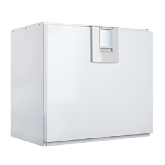
MAINTENANCE INSTRUCTIONS BEFORE YOU START MAINTENANCE WORK When you open the device door, the safety switch (S) cuts the power. Despite this, disconnect the power supply. Always disconnect the power before starting the ventilation unit maintenance. There are two equipment models, left (L) and right-handed (R). The figure below depicts the right-handed model. - Page 39 MAINTENANCE INSTRUCTIONS If you want to change the filters, proceed as follows: 1. Disconnect the power for the ventilation unit. 2. Open the ventilation unit door by lifting the latch. 3. Lift the door off. 4. Remove the old filters (A, B, C) and discard them. 5.
-
Page 40: Heat Recovery Cell
MAINTENANCE INSTRUCTIONS FANS Check the cleanliness of the fans in conjunction with the filters and heat recovery cell maintenance. Clean the fans, if necessary. You can clean the fan blades with compressed air or by brushing them with a brush. Do not remove or move the fan blade balancing pieces. - Page 41 MAINTENANCE INSTRUCTIONS by two wing screws (DV110 and DV145) or screws (DV96) from below (figure 5). 8. Pull the radiator and the support out of the unit (figures 6 and 7) and remove the quick connector for the radiator wire. WARNING Make sure that the radiator is not hot, before you pull it out of the unit.
- Page 42 MAINTENANCE INSTRUCTIONS CLEANING THE EXTRACT AIR FAN When you want to clean the extract air fan, proceed as follows: 1. Disconnect the power for the ventilation unit. 2. Open the ventilation unit door by lifting the latch. 3. Lift the door off. Please note that the door is heavy. 4.
-
Page 43: Condensing Water
MAINTENANCE INSTRUCTIONS CONDENSED WATER NOTE In the heating season, the extract air humidity condenses to water. Water formation may be abundant in new buildings, or if There may be some water in the the ventilation is low, compared to the humidity production of condensed water pool, at the residents. -
Page 44: Technical Specifications
TECHNICAL SPECIFICATIONS DV96 TECHNICAL SPECIFICATIONS – Product models Additional heating DV96 (R) Adroit radiator DV96 (L) Adroit Supply Air 92 l/s, 331m /h, 100 Pa Supply Air 0.119kW, 0.9A EC Air volumes Fans 95 l/s, 342m /h, 100 Pa Extract Air Extract Air 0.119kW, 0.9A EC 230V, 50Hz 5.1A... - Page 46 TECHNICAL SPECIFICATIONS DV110 TECHNICAL SPECIFICATIONS Power, 900W Product models Additional heating DV110 (R) Adroit radiator DV110 (L) Adroit Supply Air 107 l/s, 386 m /h, 100 Pa Supply Air 0.119kW, 0.9A EC Air volumes Fans 113 l/s, 407m /h, 100 Pa Extract Air Extract Air 0.119kW, 0.9A EC...
- Page 50 INTERNAL ELECTRICAL CONNECTION DV96 4. Supply fan tacho (WT) 5. GND (GN) 6. Supply fan PWM (YE) 1. Extract fan tacho (WT) 2. GND (GN) 3. Extract fan PWM (YE)
-
Page 51: Internal Electrical Connection
INTERNAL ELECTRICAL CONNECTION DV110 4. Supply fan tacho (WT) 5. GND (GN) 6. Supply fan PWM (YE) 1. Extract fan tacho (WT) 2. GND (GN) 3. Extract fan PWM (YE) - Page 52 INTERNAL ELECTRICAL CONNECTION DV145 4. Supply fan tacho (WT) 5. GND (GN) 6. Supply fan PWM (YE) 1. Extract fan tacho (WT) 2. GND (GN) 3. Extract fan PWM (YE)
-
Page 53: External Electrical Connection
EXTERNAL ELECTRICAL CONNECTION DV96, DV110 AND DV145... - Page 54 EXTERNAL ELECTRICAL CONNECTION FOR CONTROLLING THE MLV 24 VDC relay/ contactor for controlling the pump and the solenoid valve Distribution board Ethernet interface on top of the unit RJ45 female MLV control Connection to mains THE VENTILATION UNIT’S INTERNAL ELECTRICAL CONNECTION MB_A External Modbus A signal MB_B...
-
Page 55: Heating/Cooling Radiator Operation Chart
HEATING/COOLING RADIATOR OPERATION CHART RADIATOR (COUNTER FLOW CONNECTION) SUPPLY AIR OUTSIDE AIR Ventilation unit INPUT FROM THE DISTRIBUTION BOARD HEAT PUMP OPERATION AND EXAMPLE WIRING ALWAYS FOLLOW PRIMARILY THE WIRING PLAN FROM THE HVAC HEAT COLLECTION CIRCUIT DESIGNER OR HEAT PUMP MANUFACTURER. The adjoining figure depicts an example wiring for connecting the heating/cooling radiator unit to the heat collection circuit. -
Page 60: Certificate Of Conformity
CERTIFICATE OF CONFORMITY DV96 , DV110 AND DV145 DECLARATION OF CONFORMITY Supplier: Airflow Development Limited Address: Aidelle House, Lancaster Road Cressex Business Park High Wycombe Bucks HP12 3QP Telephone number: 01494 525252 E-mail: info@airflow.com Web: airflow.com Description of Unit: Ventilation unit with heat recovery DV50 Adroit DV80 Adroit Model:... -
Page 64: User Level Diagrams
USER LEVEL DIAGRAMS EXTENSIVE Away Away info Edit Error log Edit Cell defrost Turn unit ON At home At home info Boost Self test display Wizard Boost info Edit Fireplace Fireplace info Service diagnostic display Edit Fan test Service Menu Heater test Language Summer-Winter test... - Page 65 USER LEVEL DIAGRAMS LIMITED Edit Away Away info Error log Turn unit ON At home At home info Edit Cell defrost Boost Wizard Boost info Edit Self test display Fireplace info Fireplace Service diagnostic display Edit Fan test Service Menu Heater test Language Summer-Winter test...
-
Page 66: Commissioning The System
COMMISSIONING THE SYSTEM The Building Regulations 2010, Statutory Instrument Part 9, paragraph 42, imposes a requirement that testing and reporting of mechanical ventilation performance is conducted in accordance with an approved procedure. Compliance with this requirement by an assessed and registered "Competent Person" should follow a "Best Practice"... -
Page 67: Warranty
WARRANTY Applicable to units installed and used within the United Kingdom. Airflow Developments Ltd guarantees the DV96, DV110, DV145 Adroit units for 5 YEARS from date of purchase against faulty material or workmanship. Motors are only covered for 1 YEAR from date of purchase against faulty material or workmanship.
Need help?
Do you have a question about the Airflow DV145 Adroit and is the answer not in the manual?
Questions and answers