Table of Contents
Advertisement
Quick Links
Advertisement
Table of Contents

Subscribe to Our Youtube Channel
Related Manuals for BPC Vent-Axia Sentinel 405215 Advance S


Summary of Contents for BPC Vent-Axia Sentinel 405215 Advance S
- Page 1 Sentinel Kinetic Advance MVHR Installation & Commissioning Stock Ref. N° 405215 Advance S 405216 Advance SX Power Heater Models 474020 Advance SXp LH 474025 Advance SXp RH PLEASE RETAIN THESE INSTRUCTIONS WITH THE PRODUCT. Copyright © 2009 Vent-Axia Limited. All rights reserved. 474957B...
-
Page 2: Warnings And Safety Information
Warnings and Safety Information Warnings and Safety Information PLEASE READ THESE INSTRUCTIONS CAREFULLY BEFORE COMMENCING INSTALLATION. 1. Do not install this product in areas where the following may be present or occur: • Excessive oil or a grease laden atmosphere. •... -
Page 3: Installation Guidance
Warnings and Safety Information Installation Guidance 1. The installer is responsible for the installation and electrical connection of the sentinel system on site. It is the responsibility of the installer to ensure that the equipment is safely and securely installed and left only when mechanically and electrically safe. 2. -
Page 4: Table Of Contents
About this Document About this document Contents UK Building Regulations (Part F) Warnings and Safety Information Declaration of Conformance Installation Guidance ..............3 The Sentinel Kinetic conforms to the 2010 Building About this document Regulation (Part F - Means of Ventilation, F1(1), F(2)) Contents .................. -
Page 5: Technical Data
Technical Data Technical Data Product Description The Vent-Axia Sentinel Kinetic Advance models S & SX Mechanical Ventilation/Heat Recovery (MVHR) is a heat recovery unit designed for the energy efficient ventilation of houses and similar dwellings, conforming to the latest requirements of the Building Regulations document F 2010. The unit is designed for continuous 24 hour exhaust ventilation of stale moist air from bathrooms, toilets, utility rooms and kitchens. -
Page 6: Product Dimensions
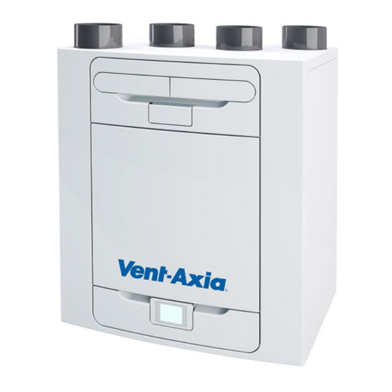
Technical Data Product Dimensions Figure 2: Sentinel Kinetic Advance Dimensions Remove front cover (see page 17) to view Rating label. (Label is positioned to the right of the controller). Sentinel Kinetic Advance MVHR Installation & Commissioning Instructions PN 474957... -
Page 7: Technical Specification
Technical Data Technical Specification Performance Sentinel Kinetic Advance S Sentinel Kinetic Advance SX Airflow default 20% default 20 l/s (72 m Normal default 30% Normal default 30 l/s (108 m Boost default 50% Boost default 50 l/s (180 m Purge default 100% Purge default 98 l/s (353 m... -
Page 8: Flow Rate Settings
Technical Data Flow Rate settings The Sentinel Kinetic Advance has four (4) user defined speeds in addition to the non-adjustable Maximum speed. User defined speeds can be assigned a Mode name from the list below. (some options may not be available in your region) - Low - Normal (Unit default operating mode) -
Page 9: Summer Bypass Mode
Technical Data Summer Bypass Mode The Sentinel Kinetic Advance includes a Summer Bypass (SBP) feature to bypass the heat exchanger to provide cooling when the desired Indoor Temperature is above the ambient temperature. Note that the volume of air provided by a ventilation system is a fraction of that required for space heating or space cooling and will not in itself be sufficient to cool a room. -
Page 10: Accessories
Technical Data Accessories Some accessories may be included as standard equipment depending on the version. 409195 WIFI Controller Accessory The WIFI controller is a plug & play accessory that fits next to the Control module. This offers the user instant access to various functions and features for direct monitoring and control of the unit using a smart phone or tablet via the Vent-Axia mobile application. -
Page 11: Installation
Installation Installation Overview Before installation of the unit We advise installers to fix all mains and sensor wiring along with any internal accessories prior to fixing the MVHR unit in position, leaving approximately 500mm tails to allow for internal routing. Inspect the Unit When taking delivery of the unit, check the items delivered against the enclosed delivery note. -
Page 12: Wall Mounting The Unit
Installation Wall Mounting the Unit Step 1: Mark the wall bracket position using the dimensions shown. Note the position of the top of the unit in relation to the wall bracket. Ensure the bracket position is horizontal. Step 2: Attach the wall bracket to the wall using appropriate fixings. -
Page 13: Floor Mounting The Unit
Installation Floor Mounting the Unit Step 1: The unit has 44 x 12mm deep fixing holes on the underside suitable for a No.6 screw. Pre drill a board using the dimensions shown, and cut 2 x 105mm minimum diameter holes for the condensate drain access. -
Page 14: Floor Mounting The Unit (Alternate Method)
Installation Floor Mounting the Unit (Alternate Method) Step 1: The unit has 44 x 12mm deep fixing holes on the underside suitable for a No.6 screw. The holes are configured to allow fitment of most standard kitchen foot types (not supplied). -
Page 15: Vertical Discharge Condensate Installation
Installation Vertical Discharge Condensate Installation Note The kinetic advance condensate outlet is compatible with standard 22 mm plastic push-fit fittings and 32mm plastic waste pipe fittings. A water trap with a seal depth of at least 60mm or a HepVo valve must be fitted between the unit and the rest of the waste system. -
Page 16: Attach The Ducting
Installation 32mm waste pipe Step 1: Attach the appropriate pipe fittings for your installation to the (RH) condensate outlet. Fit the drain cap supplied with the unit to the opposite (LH) condensate outlet. Ensure the sealing gasket is fitted inside the blanking cap. -
Page 17: Electrical Installation
Installation Electrical Installation ! Ensure the electrical supply and controls are isolated before removing access covers ! Step 1: Remove the outer cover by pressing the tabs either side of the control module and lifting the cover outwards from the bottom edge. Step 2: Remove the control module by sliding it upwards and away from the unit. -
Page 18: Connect Switches And Sensors
Installation Connect Switches and Sensors The unit can be switched to boost by applying 240V to the LS input . Note: Alternative switches and inputs can be achieved by adding optional input accessories to the printed circuit board. See Accessories on page 10 for further details. For good EMC engineering practice, any sensor, switched live or Volt free cables should not be installed within 50mm of other cable or on the same metal cable tray as other cables. - Page 19 Installation Other means of connecting the unit may be used if they meet the local wiring regulations. SEE NOTES ON PAGE 20 Terminal No. Name Description (Control Mode 01) REMOTE Remote Terminals for connecting a remote external to the unit. Switch 1 Volt-free contact for sensor input between + and - terminals Red Light Emitting Diode...
-
Page 20: Connect The Power Supply
Installation Connect the Power Supply WARNINGS 1. MAINS SUPPLY VOLTAGES (220-240 V AC) ARE PRESENT IN THIS EQUIPMENT, WHICH MAY CAUSE DEATH OR SERIOUS INJURY BY ELECTRIC SHOCK. ONLY A SUITABLY QUALIFIED PERSON SHOULD CONNECT THE POWER SUPPLY TO THIS UNIT. 2. -
Page 21: Commissioning
Commissioning Commissioning Powering up the Unit Switching On To switch the unit on: 1. Switch on the power at the mains supply isolator feeding the unit. 2. Following switch-on, the fan motors will start and the Control Unit will display a start-up screen, described on page 22. -
Page 22: Modifying Settings
Commissioning Modifying Settings If settings need to be changed after the unit has been commissioned, access to the commissioning menu can be accessed by following the steps below. Start up screen Every time the unit is powered up, the start up screen appears as the software loads showing the display version. -
Page 23: Commissioning Screens Summary
Commissioning Commissioning Screens Summary The following pages show all available settings within the commissioning menu. Please note that some settings may not be available, or may be in a different order, due to pre-configuration by your distributer. A Quick Start sequence will appear when powering up the unit for the first time. Sentinel Kinetic Advance MVHR Installation &... - Page 24 Commissioning Sentinel Kinetic Advance MVHR Installation & Commissioning Instructions PN 474957...
-
Page 25: Modifying Commissioning Settings
Commissioning Modifying Commissioning Settings Country Select country – This will load any pre-determined national default parameters for all subsequent screens. Language Select language – The language choice does not affect the defaults setup by the country choice. Load USB Settings Settings can be automatically loaded to the unit via the USB port. - Page 26 Commissioning Unit configuration Select the orientation of the unit depending on the configuration of the installation. Units with a preheater are preconfigured from the factory and cannot be changed. See page 11 for a description of the unit handing. Press to save and return to the commissioning menu.
- Page 27 Commissioning Mode Names The names and speed for each mode can be changed if required. Note: The user mode 1, Normal, is not editable. Scroll through the settings using the & buttons and select the mode pre-set for each User mode.
- Page 28 Commissioning Port Allocation The unit will automatically detect the following inputs: - wired to the lighting - Current sensors - Vent-wise sensors or momentary switch Note: Number of available ports and port types may differ from image shown depending on unit specification.
- Page 29 Commissioning Summer Bypass See page 9 for a full description of the Summer Bypass modes and functions Select the required bypass mode. The indoor temperature setting is the maximum desired room temperature. This should be set to 3° above the central heating temperature. Change the indoor temperature using the buttons on the screen.
- Page 30 Commissioning Internal RH Trip The integral humidity sensor increases airflow speed in proportion to relative humidity levels. The sensor also reacts to small but rapid increases in humidity, even if the normal trigger threshold is not reached. The night time relative humidity setback feature suppresses nuisance tripping as humidity gradually increases with falling temperature.
- Page 31 Commissioning Frost Protection Frost Protection is required to prevent condensate freezing in the heat exchanger at low temperatures. The process is fully automatic. The method used for frost protection will depend on the model and building it is installed in. For buildings with a leak rate of 3m /hr or less (at 50Pa), a balanced frost protection mode must be...
- Page 32 Commissioning Mode Scheduling Use a schedule to set a Mode (Airflow setting) for a fixed, repeated period. For example, set Boost Mode every morning between 7:00am and 8:00am while cooking breakfast. Select the Schedule to view the settings Scroll through the settings using the &...
- Page 33 Commissioning Service Phone The Service Phone screen enables the installer to enter the telephone number that should be called for service in the event of a unit fault or for routine maintenance. Enter the number using the buttons on the screen, Scroll through the number using the buttons.
-
Page 34: Operation And Monitoring
Operation and Monitoring Operation and Monitoring Control Unit Screens Summary The following Control Unit screens are available for daily operation and monitoring of the unit. Sentinel Kinetic Advance MVHR Installation & Commissioning Instructions PN 474957... - Page 35 Operation and Monitoring Control Unit Screens Summary The following Control Unit screens are available in the Settings / Performance section. Sentinel Kinetic Advance MVHR Installation & Commissioning Instructions PN 474957...
-
Page 36: User Controls
Operation and Monitoring User controls User Menu Home Screen The user menu home screen, consists of a User Mode (BOOST) button, a Machine status bar, and a Settings / Performance bar. The Machine status scrolls through Mode of operation, Summer bypass status and Frost protection status. -
Page 37: Settings And Performance
Operation and Monitoring Settings and Performance Settings Scroll through the settings using the & buttons and select using where applicable to access Language, Date, Time, Reset filter, Display settings, Summer Bypass, Mode Scheduling, Service phone, Commissioner Menu & Diagnostics. Days Run and Filter check are reported values and do not have editable parameters in this section. - Page 38 Operation and Monitoring Time Change the time using the buttons on the screen. Note: The clock is 24 hour Clean/Replace Filter After maintenance or replacement of the filters, the filter timer can be reset by pressing . Press to return to the Settings Menu. Display Settings Change the brightness of the touch screen using buttons.
- Page 39 Operation and Monitoring The outdoor temperature is the minimum air temperature that the bypass will permit. This is to prevent cold draughts. Change the indoor temperature using the buttons on the screen. This is the mode the bypass will switch to when activated.
- Page 40 Operation and Monitoring Adjust the start and finish times for each day using buttons. Silent Hours Silent Hours mode is useful to impose a speed/flow restriction on the unit to minimise unwanted noise during the night. If Silent hours are enabled, the unit will not speed up above the set Maximum Mode.
-
Page 41: Commissioning The Unit Via Usb
Operation and Monitoring Diagnostics Scroll through the Diagnostics list using the & buttons to access the following information. Machine Status, Days Run, Filter Check, Bypass, Energy Consumption, Air flows, Option boards. Input status, Output Status, WiFi Status, WiFi signal. Note: Optional upgrades may be necessary to view all information. -
Page 42: Default Settings
Operation and Monitoring Default settings Parameters Settings Commissioning Screens Country United Kingdom Language English. Date Automatic - Factory set Time Automatic GMT/BST - Factory set Unit configuration Right Hand Filter Check 12 months Summer Bypass Normal Mode Names Normal, Boost, Low, Purge User Mode Boost Supply/Extract 50 %... -
Page 43: Control Via Wifi
Operation and Monitoring Control via WiFi The Kinetic Advance WiFi controller is a plug & play accessory that fits next to the control module. It allows the user instant access to commissioning, configuration, direct monitoring and control of the MVHR unit, using a smart phone or tablet with the Vent-Axia Connect app, available from the iTunes Store or on Google Play. - Page 44 Operation and Monitoring TROUBLESHOOTING LED Status Description Actions Solid blue Initialising Slow blue flash Connecting to a wireless network None - normal operation Solid green Connected to a wireless network Fast green flash Active communication with a connected network Solid yellow WiFi controller is hosting a temporary network, Connect phone or tablet to the AP SSID without a device currently connected...
-
Page 45: Maintenance
Maintenance Maintenance Filter Maintenance Heat recovery units require regular maintenance. The Sentinel Kinetic has been designed to facilitate access to enable maintenance to be carried out easily. When the unit displays “Clean or replace filters”. This is a reminder to ensure that the filters are not so dirty that they are blocking the airflow or allowing dirt to pass through. -
Page 46: Periodic Maintenance
Maintenance Periodic Maintenance WARNING THE FAN AND ANCILLARY CONTROL EQUIPMENT MUST BE ISOLATED FROM THE POWER SUPPLY DURING MAINTENANCE. Fan Filters Check fan filters as described on the previous page. Heat Exchanger Cell Step 1: Remove the outer cover by pressing the tabs either side of the control module and lifting the cover outwards from the bottom edge. -
Page 47: Spares
Maintenance Spares The following spare parts may be ordered from Vent-Axia: Part No Description 472663 Main Power Board 472665 Control Module 472667 Filters G3, 2 per pack 472669 Filters M5, 1 per pack 472671 Filters F7, 1 per pack 472673 Motor Scroll Assembly 472675 Summer Bypass Motor Assembly... -
Page 48: Troubleshooting
Maintenance Troubleshooting Diagnosing a Problem In the event of a problem, always troubleshoot the unit according to: Fault code displayed on the Control Unit. Fault LED if connected. If no indications are displayed, then troubleshoot problem according to the fault symptom as described in the following tables. - Page 49 Notes This page is intentionally blank and can be used for making notes regarding the product fiche Sentinel Kinetic Advance MVHR Installation & Commissioning Instructions PN 474957...
- Page 50 Notes This page is intentionally blank and can be used for making notes regarding the product fiche Sentinel Kinetic Advance MVHR Installation & Commissioning Instructions PN 474957...
-
Page 51: Product Fiche
Product fiche Name: Vent‐Axia Kinetic Advance S ‐ 405215 Kinetic Advance SX ‐ 405216 Model ID (Stock Ref.) : Kinetic Advance SX Pre‐heat LH ‐ 474020 Kinetic Advance SX Pre‐heat RH ‐ 474025 SEC Class A+ SEC Value ('Average') ‐43.85 SEC Value ('Warm') ‐18.25 SEC Value ('Cold') ‐89.33 Label Required? (Yes/No=Out of scope) Yes Declared as: RVU or NRVU/UVU or BVU RVU/BVU Speed Drive Variable Speed Type HRS (Recuperative, Regenerative, None) Recuperative Thermal Eff: [ (%), NA(if none)] 93 Max. Flow Rate (m3/h) 378 Max. Power Input (W): (@Max.Flow Rate) 190 LWA: Sound Power Level (dB) 50.0 Ref. Flow Rate (m3/s) 0.07350 Ref. Pressure Diff. (Pa) 50 SPI [W/(m3/h)] 0.25 Control Factor & Control Typology: (CTRL/ Typology) Control Factor; CTRL ... - Page 52 Guarantee Applicable only to products installed and used in the United Kingdom. For details of guarantee outside the United Kingdom contact your local supplier. Vent-Axia guarantees its products for two years from date of purchase against faulty material or workmanship. In the event of any part being found to be defective, the product will be repaired, or at the Company’s option replaced, without charge, provided that the product:- ...
Need help?
Do you have a question about the Vent-Axia Sentinel 405215 Advance S and is the answer not in the manual?
Questions and answers