Advertisement
Quick Links
Light My Bricks
Installation Instructions for Light My Bricks LED Lighting Kits
May 21 · 24 min read
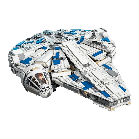
Light My Bricks: LEGO Kessel Run
Millennium Falcon 75212 Lighting Kit
The following page is instructions for the Light My Bricks LEGO Kessel
Run Millennium Falcon (75212) LED lighting kit. You purchase this kit on our
o cial website.
. . .
Advertisement

Related Manuals for LIGHT MY BRICKS LEGO Kessel Run Millennium Falcon 75212


Summary of Contents for LIGHT MY BRICKS LEGO Kessel Run Millennium Falcon 75212
- Page 1 May 21 · 24 min read Light My Bricks: LEGO Kessel Run Millennium Falcon 75212 Lighting Kit The following page is instructions for the Light My Bricks LEGO Kessel Run Millennium Falcon (75212) LED lighting kit. You purchase this kit on our o cial website.
-
Page 2: Package Contents
Package Contents: 6x White 15cm Bit Lights • 3x Flashing White 15cm Bit Lights • 2x Red 30cm Bit Lights • 1x Blue 30cm Bit Lights • 5x White Strip Lights • 1x Multi E ects Board • 1x Flicker E ects Board •... - Page 3 CAUTION: Forcing LEGO® to connect over a cable can result in damaging the cable and light. Connecting cable connectors to Expansion Boards Take extra care when inserting connectors to ports of Expansion Boards. Connectors can be inserted only one way. With the expansion board facing up, look for the soldered “=”...
- Page 4 Incorrectly inserting the connector can can result in bent pins inside the port or possible overheating of the expansion board when connected. Connecting cable connectors to Strip Lights Take extra care when inserting connectors to ports on the Strip Lights. Connectors can be inserted only one way.
- Page 5 Installing Bit Lights under LEGO® bricks and plates. When installing Bit Lights under LEGO® pieces, ensure they are placed the correct way up (Yellow LED component exposed). You can either place them directly on top of LEGO® studs or in between. .
- Page 6 Disconnect the 1x2 technic brick and then disconnect the trans-light blue tile from the back of it.
- Page 7 2.) Take a White 15cm Bit Light and then thread the connector side through the blue technic pin. Thread it all the way through until the Bit Light is right up against the technic pin, then bend the Bit Light slightly so that it sits at.
- Page 8 3.) Reconnect the 1x2 Technic brick back to the escape pod and thenreconnect pieces we removed earlier.
- Page 9 4.) Repeat previous steps to install another White 15cm Bit Light to the right side of the escape pod.
- Page 10 5.) Take a 6-Port Expansion Board and connect both bit lights to the available ports.
- Page 11 6.) Disconnect the following white 2x2 tile from the centre of the maindoor then use a LEGO removal tool to disconnect the Trans Clear 1x2 Plate. 7.) Take 2x White 15cm Bit Lights and then hold them together as shown below.
- Page 12 With the cables facing toward the back, place both lights over the following studs (underneath where the trans clear 1x2 plate was) and then reconnect the Trans Clear 1x2 Plate over the top. Reconnect the white LEGO 2x2 tile over on top.
- Page 13 8.) Disconnect the 2x4 tile toward the back and then carefully slip thecables in between the two long LEGO plates as shown below. Reconnect the 2x4 tile over the top.
- Page 14 9.) From underneath the main door, take the two cables and connectthem to spare ports on the expansion board. 10.) Disconnect the following sections from the back of the escape pod:...
- Page 15 Disconnect and disassemble the middle section from the back piece as per below:...
- Page 16 11.) Take another 2x White 15cm Bit Lights and place each in between studs with each cable facing outward. Reconnect the trans light blue 2x2 round brick...
- Page 17 12.) Bend both cables down before reconnecting this to the back piece. 13.) Take the Flat Battery Pack and insert 2x CR2032 Batteries to it. Thread the battery pack cable through the back of the escape pod in the space at the bottom left corner.
- Page 18 Pull it all the way through and then connect it to a spare port on the 6port expansion board.
- Page 19 14.) Take the back piece and then thread each bit light cable through the corner space on each side, then reconnect this back piece as per below...
- Page 20 15.) Reconnect surrounding pieces we removed earlier. 16.) Take the Flicker E ects Board and then connect the two cables from the back light to the OUT ports...
- Page 21 17.) Take a 5cm Connecting Cable and connect this to the IN port on the icker e ects board. Connect the other side of the cable to the remaining port on the 6-port expansion board. Turn the battery pack ON to test all lights are working OK (including the icker e ect for the back jet)
- Page 22 18.) Neatly place all the cables and boards inside the escape pod andthen close the door. 19.) Tuck the at battery pack in underneath the escape pod inbetween the grey plates.
- Page 23 Pull in any excess cable from the battery pack. This completes installation of the lights for the Escape Pod.
- Page 24 . . . Lighting the Kessel Run 1.) Open up the Kessel Run and then disconnect the following piecesfrom the left side of the ship.
- Page 25 Disconnect the two white arch pieces and then take a White Strip Light.
- Page 26 2.) Connect a 30cm Connecting Cable to the left port of the strip light and then connect a 15cm Connecting Cable to the right port .
- Page 27 3.) Using it’s adhesive backing, stick the strip light underneath the twowhite arch pieces in the following position. Ensure the 30cm Connecting cable is facing the left and the 15cm Connecting cable is facing the right.
- Page 28 Reconnect the arch piece section ensuring the cables underneath are laid in between studs.
- Page 29 4.) Pull the 30cm connecting cable across and around the side of theship toward the back.
- Page 30 Reconnect surrounding pieces we removed earlier from the middle. 5.) Disconnect the long section from the back of the ship as per below:...
- Page 31 6.) Take 3x White Strip Lights and 2x 5cm Connecting Cables. Connect them all together as per below: 7.) Take the other end of the 30cm Connecting Cable from previoussteps and then connect this to the end of one of the Strip Lights.
- Page 32 8.) Take a Flashing White 15cm Bit Light and connect it to the end of the Strip Light on the other side. 9.) Using the strip light’s adhesive backing, stick each one to thefollowing sections starting from the left side. You can disconnect surrounding sections to make it easier to stick down the strip lights.
- Page 34 10.) Disconnect the hyperdrive section and then remove the trans lightgreen brick.
- Page 35 11.) Place the Flashing White 15cm Bit Light over the top of the translight green brick (with LED facing down) then reconnect the hyperdrive section over the top to secure the light in place. You will notice that the Bit Light is slightly bent up. Use a thin LEGO bar to push the component down so that the light is facing directly down.
- Page 36 12.) Reconnect the hyperdrive with bit light installed back to the kesselrun and then neatly lay excess cable behind the unit.
- Page 37 13.) Pull excess cable from the rst strip light back inside the kessel runthen lay the cable in between studs underneath the following section.
- Page 38 14.) Reconnect the back long section over the strip lights and then pushdown any excess connecting cables in between strip lights.
- Page 39 15.) Take the AA Battery Pack and insert 3x AA Batteries to it. Place the Battery Pack inside the Kessel Run towards the back in the following position (with battery pack cable at the top)
- Page 40 Disconnect the following sections to allow us to lay the battery pack cable down towards the centre of the Kessel Run underneath these sections before reconnecting them.
- Page 41 16.) Take a 6-port Expansion Board and then connect the other end of the connecting cable from the very rst Strip Light we installed as well as the Battery Pack cable to the available ports. Turn the Battery Pack On to test that all lights we have installed so far are working OK.
- Page 42 17.) Turn the Kessel Run over to the other side and then disconnect thefollowing sections to allow us to remove the two white arched pieces.
- Page 44 18.) Take another White Strip Light and connect a new 15cm Connecting Cable to the left port. Take a Blue 30cm Bit Light and connect it to the Strip Light’s right port. 19.) Using it’s adhesive backing, mount the strip light underneath thetwo white arch pieces in the following position...
- Page 45 Reconnect this section back ensuring the Blue Bit Light is facing down and 15cm Connecting Cable is facing up and laid in between studs. Connect the other end of the 15cm Connecting Cable to a spare port on the 6-port Expansion Board in the middle.
- Page 46 17.) Disconnect the following section that leads to the cockpit as wellas the cockpit cover section.
- Page 47 18.) Thread the end of the Blue 30cm Bit Light through the space thatleads to the back of the cockpit.
- Page 48 Pull the Bit Light out from the front and then lay it on top of the following stud: Secure the Bit Light in place by connecting the provided Trans Clear Round Plate 1x1 over the top.
- Page 49 19.) Pull the excess cable out through to the front and then secure thecables underneath the following LEGO piece.
- Page 51 Disconnect the following pieces from the front of the cockpit, pull the cable out to the left in between studs and then reconnect the pieces over the top.
- Page 52 Tuck the excess cable down underneath the cockpit and then place Han Solo inside. Reconnect the cockpit window and then turn the Battery Pack ON to verify everything you have installed so far is working OK...
- Page 53 20.) Reconnect the roof that leads to the cockpit as well as piecesaround the centre of the ship we removed earlier.
- Page 54 21.) We will now install ashing lights to the control panel at the frontof the vehicle. Disconnect the following pieces to give us access inside.
- Page 57 Disconnect the two trans red 1x2 plates as well as the 1x4 plate behind.
- Page 58 22.) Take a Flashing White 15cm Bit Light and with the cable facing toward the back, place it on top of the following stud. Secure the light in place by reconnecting one of the trans red 1x2 plates over the top. Repeat this step to install another Flashing White 15cm Bit Light to the other side.
- Page 59 23.) Reconnect some of the surrounding pieces we removed earlier.
- Page 60 Take the two Flashing Bit Lights and connect them to the 6-port Expansion Board...
- Page 61 Turn the Battery Pack ON to verify everything you have installed so far is working OK Reconnect the top cannon section.
- Page 62 24.) Carefully turn the entire Kessel Run over to access underneath.Place your hands over the top of the back section to ensure the AA Battery Pack doesn’t fall out. Disconnect the lower cannon section as and then disconnect the dark grey cone piece from the front of the canon as per below:...
- Page 63 25.) Take a Red 30cm Bit Light and thread the connector end of the cable through the base of the cone. Thread the cable all the way through and then slightly bend the LED component on a 90 degree angle so that it sits at against the edge of the cone piece.
- Page 64 Reconnect the cone piece to the cannon bar and then pull the cable down and secure underneath the following dark grey 2x2 tile. Ensure the cable is laid in between studs...
- Page 65 26.) Thread the cable down (up through to the top side) through thecentre of the Kessel Run before securely reconnecting the lower cannon section.
- Page 66 Carefully turn the entire Kessel Run over and pull the Bit Light cable from the lower canon up from the centre.
- Page 67 27.) Take the Multi E ects Board and connect the other end of the Red 30cm Bit Light to one of the output ports (side with two ports). Set this e ects board aside for now and proceed to next step. 28.) Disconnect the upper canon section and then disconnect the darkgrey cone piece from the front of the canon as per below:...
- Page 68 29.) Take the remaining Red 30cm Bit Light and thread the connector end of the cable through the base of the cone. Thread the cable all the way through and then slightly bend the LED component on a 90 degree angle so that it sits at against the edge of the cone piece.
- Page 69 Reconnect the cone piece to the cannon bar and then pull the cable down and secure underneath the following dark grey 2x2 tile. Ensure the cable is laid in between studs...
- Page 70 30.) Reconnect the upper canon section to the top of the kessell runand then connect the other end of the Red 30cm Bit Light to the other output port on the multi e ects board. 31.) Take a 5cm Connecting Cable and connect one end to the input port of the Multi E ects Board and then connect the other end to the remaining port on the 6-port expansion board.
- Page 71 32.) Con gure the e ects board but turning the switch to the middlechannel for “emergency” e ect and then turn the speed wheel all the way to the left for the slowest e ect. This setting will set the “ ring canon” e ect.
- Page 72 33.) Neatly tuck all the components and cables down through centrehole and then close up the upper cannon door.
- Page 73 Reconnect the escape pod to the front of the ship. This nally completes installation of the Kessel Run Millennium Falcon Light Kit. Now turn on the light kit using both battery packs and ENJOY! . . .
Need help?
Do you have a question about the LEGO Kessel Run Millennium Falcon 75212 and is the answer not in the manual?
Questions and answers