Advertisement
Quick Links
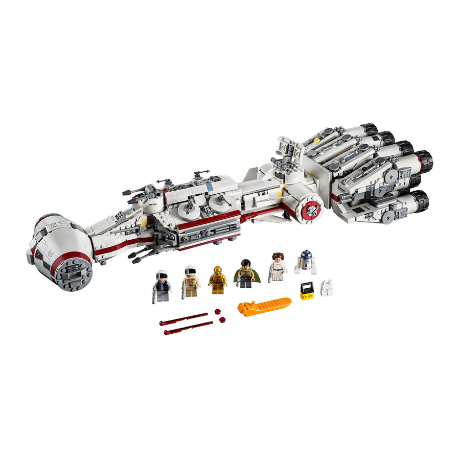
Light My Bricks: LEGO Star Wars Tantive IV
75244 Lighting Kit
The following page is the instructions for the
Light My Bricks LEGO Star Wars
Tantive IV (75244) LED light kit.
If you run into any issues, please refer to the
online troubleshooting guide.
To ensure a trouble-free installation of your light kit, please read and follow
each step carefully. These instructions can be downloaded in PDF format
here
Please note: This page lists instructions for the LED light kit only. If you are
wishing to purchase the Light My Bricks LEGO Star Wars Tantive IV (75244) LED
light kit , please click
here
to view the product page
Advertisement

Related Manuals for LIGHT MY BRICKS 75244


Summary of Contents for LIGHT MY BRICKS 75244
- Page 1 These instructions can be downloaded in PDF format here Please note: This page lists instructions for the LED light kit only. If you are wishing to purchase the Light My Bricks LEGO Star Wars Tantive IV (75244) LED light kit , please click here...
-
Page 2: Package Contents
Package Contents: 11x White 30cm Bit Lights 10x Cool White 30cm Bit Lights 4x Red 30cm Bit Lights 2x Flashing Red 30cm Bit Lights 4x 6-Port Expansion Boards 1x 8-Port Expansion Boards 1x 12-Port Expansion Boards 1x Multi Effects Board 1x Gun Effects Board 1x Set of Wireless Power Connectors (possitive and negative) 2x 5cm Connecting Cables... - Page 3 Cables can fit in between and underneath LEGO® bricks, plates, and tiles providing they are laid correctly between the LEGO® studs. Do NOT forcefully join LEGO® together around cables; instead ensure they are laying comfortably in between each stud. CAUTION: Forcing LEGO® to connect over a cable can result in damaging the cable and light.
- Page 4 Incorrectly inserting the connector can can result in bent pins inside the port or possible overheating of the expansion board when connected. Connecting cable connectors to Strip Lights Take extra care when inserting connectors to ports on the Strip Lights. Connectors can be inserted only one way.
- Page 5 correct way up (Yellow LED component exposed). You can either place them directly on top of LEGO® studs or in between. OK, Let’s Begin! 1.) We will first install lights to the cockpit. Start by disconnecting the roof section on each side, then disconnect the following middle sections as shown below:...
- Page 6 Disassemble the middle section as shown below, then take the red and trans dark clear pieces.
- Page 7 2.) Take 2x Cool White 30cm Bit Lights and with the cables facing the right side, place both of them over the studs of the red plate. Secure them in place by reconnecting the trans dark clear plates over the top. The 2 LEDs should fit nicely inside the studs of the trans dark clear plates.
- Page 8 Reconnect the following section on top, then flip it over and push the cables down into the corner before reconnecting it to the two white arch bricks. Lay the two cables down the middle in between studs before reconnecting the right section over the top of the cables.
- Page 9 Flip this section over and ensure both cables are tucked in between white bricks, then flip it back over and reconnect the middle section on top.
- Page 10 3.) Take a new Cool White 30cm Bit Light and using an Adhesive Square, stick it underneath the middle section in the below position with cable facing the back.
- Page 11 Slip the Bit Light Cable in between the two centre arched bricks, then lay it out toward the back before reconnecting the grey 2×3 plate over the top of the cables. Ensure the cable is laid in between studs. 4.) Connect the cables from the three bit lights we have just installed to a 6- Port Expansion Board.
- Page 12 expansion board. Connect the USB end to a USB Power Bank (sold separately) and turn it ON to test the lights are working OK. Note: If you experience any issues with the lights not working and suspect an issue with a component, please try a different port on the expansion board to verify where the fault lies (with the light or expansion board).
- Page 13 Disconnect the USB Power Cable from the expansion board, then reconnect the middle section back to the front of the ship. Neaten up the wiring and eliminate excess cable from the Bit Lights by grouping them together and twisting/folding them together into a neat bunch as shown below. Place the expansion board in to the middle section behind.
- Page 14 5.) Remove cabin roof as well upper cannon section, then take a 15cm Connecting Cable and connect it to the 6-Port Expansion Board. Bring the other end of the 15cm Connecting Cable toward the back, then slip it in between the middle and side sections as shown below.
- Page 15 Disconnect the following white square plate and lay the cable in between studs underneath, before reconnecting the square plate over the top.
- Page 16 6.) Open the lower compartment, then bring the cable out the side to connect to the first port on a 12-Port Expansion Board Reconnect the USB Power Cable to the last port on the 12-Port Expansion Board and connect up the USB Power Bank to test the cockpit lights are working OK.
- Page 17 Note: If you experience any issues with the lights not working and suspect an issue with a component, please try a different port on the expansion board to verify where the fault lies (with the light or expansion board). To correct any issues with expansion board ports, please view the section addressing expansion board issues on our online troubleshooting guide.
- Page 18 7.) Take a 5cm Connecting Cable and connect it to the 12-Port Expansion Board, connect the other end of the cable to the IN (+5V) port on the Gun Effects Board (G3FX V1). Place the Tantive IV onto it’s side to allow us to disconnect the lower cannon section, then disassemble this section as shown below:...
- Page 19 8.) Take a Red 30cm Bit Light and thread the connector end of the cable all the way through the top of one of the grey cone pieces. Carefully bend the Bit Light so that the LED sits flat against the top of the cone piece, then reconnect grey bar at the bottom before reconnecting it back to the cannon base.
- Page 20 Repeat this step to install another Red 30cm Bit Light to the other cannon.
- Page 21 9.) Turn the cannon section over to the top side and bring both cables down toward the back before reconnecting it back to the white round brick.
- Page 22 Thread the two cables through the lower compartment of the ship before reconnecting the lower cannons underneath. Flip the ship back over and connect the two bit light cables to OUT ports 3 and 4 of the Gun Effects Board.
- Page 23 The Gun Effects Board has 3 different gun effects, which can be configured via the 3-way switch. The effect used in the product video example is the Cannon (blaster) effect which can be set by flicking the switch to the far right. Turn your USB Power Bank ON and choose your desired effect.
- Page 24 Using the same method used for the lower cannons, install another 2x Red 30cm Bit Lights to the upper cannons.
- Page 25 11.) Take the bottom section of the upper cannons and disconnect the back Turn the cannons over and bring both cables down the middle before reconnecting back to the bottom section. Ensuring both cables are laid down the middle and in between studs, reconnect the back section.
- Page 26 12.) Reconnect the upper cannon section to the top of the ship, then lay the two bit light cables down behind to connect to OUT ports 1 and 2 on the Gun Effects Board. Turn the USB Power Bank ON to test both upper and lower cannons are working OK.
- Page 27 Note: If you experience any issues with the lights not working and suspect an issue with a component, please try a different port on the expansion board to verify where the fault lies (with the light or expansion board). To correct any issues with expansion board ports, please view the section addressing expansion board issues on our online troubleshooting guide.
- Page 28 13.) We will now install lights to the inside of the cabin area. First disconnect the corner table, then disconnect the black plate with bar from underneath. Take a Cool White 30cm Bit Light and with the cable facing the back, stick it underneath the table in the following position using an Adhesive Square.
- Page 29 Turn the Tantive over to the other side and open up the lower compartment. Thread the other end of the Bit Light cable through the following hole of the white technic brick underneath. Thread the cable all the way through to the other side, then turn the Tantive back around and pull the cable all the way out.
- Page 31 Turn ON the USB Power Bank to test the light under the table is working OK. Note: If you experience any issues with the lights not working and suspect an issue with a component, please try a different port on the expansion board to verify where the fault lies (with the light or expansion board).
- Page 32 Take 2x Cool White 30cm Bit Lights and with the cables facing behind, place them over the studs of the angled white bricks. Secure them in place by connecting a provided Trans Clear Plate 1×2 over the top. Reconnect this section to the front of the cabin area and then run the cables down behind the wall.
- Page 34 Note: If you experience any issues with the lights not working and suspect an issue with a component, please try a different port on the expansion board to verify where the fault lies (with the light or expansion board). To correct any issues with expansion board ports, please view the section addressing expansion board issues on our online troubleshooting guide.
- Page 35 Neaten up cabling running down the side by tucking them into the corner, then secure them to the wall using tape. Fold in the corner wall section to secure down all the cables. 16.) We will now install some flashing red lights to the back of the cabin floors.
- Page 36 In order to get to them, follow the below images to disconnect the following sections:...
- Page 37 Disconnect the white 1×2 bricks with trans red round plate underneath them from each side. Disconnect the trans red round plates from underneath...
- Page 38 17.) Take a Flashing Red 30cm Bit Light and with the cable facing toward the back, place it over the corner stud on the floor of the cabin. Secure the Bit Light in place by reconnecting one of the trans red round plates over the top. Repeat this step to install another Flashing Red 30cm Bit Light to the other side of the cabin floor.
- Page 39 Take the bit light cable from the left side (closest to you) and connect it to the 12-Port Expansion Board. 18.) Turn the Tantive IV over onto it’s left side (pull towards you) and take the bit light cable from the right side and thread it all the way through the following hole of the white technic brick underneath.
- Page 40 Turn the Tantive IV over onto it’s right side and pull the cable all the way out from underneath. Connect the bit light cable to the next available port on the 12-Port Expansion Board.
- Page 41 Turn the USB Power Bank ON to test the flashing red lights on the cabin floor are working OK. Note: If you experience any issues with the lights not working and suspect an issue with a component, please try a different port on the expansion board to...
- Page 42 verify where the fault lies (with the light or expansion board). To correct any issues with expansion board ports, please view the section addressing expansion board issues on our online troubleshooting guide. 19.) Take a 30cm Connecting Cable and connect it to the 12-Port Expansion Board.
- Page 43 Reconnect all the sections to the cabin floor which we removed earlier.
- Page 44 20.) We will now neaten up all the messy cables underneath the cabin. Twist and fold the cables into two neat bunches and ensure the bunches are thin, as shown below Disconnect the lower compartment section, then push the two bunches of cables on the right all the way into the technic brick holes as per below:...
- Page 45 Lay the larger bunch of cables (left) from the cannon lights across the middle, toward the back, then place the Gun Effects Board flat up against underneath the cabin floor plate. Reconnect the lower compartment section and fold it up to secure all the components and cables neatly inside.
- Page 46 21.) Remove the spare laser pieces from behind, then disconnect the white 1×4 tile from the back. Lay the other end of the 30cm Connecting Cable inside before reconnecting the white tile over the top. Replace the spare laser pieces.
- Page 47 22.) Take the cabin roof section and disconnect the following dishes before disconnecting each side as shown below:...
- Page 48 Disconnect the following pieces from the left section, then take a Cool White 30cm Bit Light and with the cable facing back, place it over the following stud. Secure the Bit Light in place by connecting a provided Trans Clear Round Plate 1×1 over the top.
- Page 49 earlier, then reconnect this left section to the middle. 23.) Take the right section and disconnect the following pieces. Ensuring the cable is facing down, install another Cool White 30cm Bit Light, securing it in place with another provided Trans Clear Round Plate 1×1. Reconnect sections we removed earlier, then reconnect the right section to the middle.
- Page 50 24.) Turn the cabin roof over and connect the two bit light cables to a new 6- Port Expansion Board.
- Page 51 Take the Positive side of the Wireless Power Connector (1×2 plate side) and fold the cable across the top of the plate, in between studs. Connect it to underneath the cabin roof in the below position (with the cable facing inside), then connect the cable to the 6-Port Expansion Board.
- Page 52 Test the wireless power connection by taking the Cabin Roof and connecting it directly on top of the cabin. Ensure the two wireless connectors connect with each other. Turn the USB Power Bank ON and the lights on the cabin roof should illuminate.
- Page 53 Remove the cabin roof again and turn it over. Neaten up the cables by folding and twisting them around each other into a neat bunch. Lay the expansion board and bunched up cables along the middle just above the black plate. Fold the two side sections in, which will secure the cables and expansion board in place.
- Page 54 25.) We will now install some lights to the side of the Tantive IV, first remove the following sections from each side by pulling them out as shown below.
- Page 55 Turn the ship onto it’s side so we can access underneath and disconnect the technic pin from the bottom of the black technic brick. Turn the ship over and completely remove the radar section by pulling it all the way out. Continue to disconnect the following pieces on top of the ship.
- Page 56 26.) Take the two side sections we removed earlier and disconnect the front plate from each one.
- Page 57 Take a Cool White 30cm Bit Light and thread the connector end of the cable through the + hole on the front plate from the left section. Pull the cable all the way out from the other side until you can neatly place the Bit Light over the white stud in between the grey pieces.
- Page 58 Repeat this step to install another Cool White 30cm Bit Light to the front plate for the right section, securing it in place using another provided Trans Clear Round Plate 1×1. Thread the cable through the top space and out the middle hole of the red technic brick underneath before reconnecting the front plate.
- Page 59 27.) Take the left section and thread the cable through the back of the middle section and underneath the red and yellow technic pieces. Pull the cable all the way out from the front side, then securely reconnect the left section to the side of the ship.
- Page 60 Repeat this step to reconnect the right side section. Ensure both cables are neatly pulled over and laid in between studs.
- Page 61 28.) Connect the two Cool White Bit Lights as well as the 30cm Connecting Cable from the front side to a new 6-Port Expansion Board. Neaten up the cables by twisting and folding them around each other to form a neat bunch...
- Page 62 Take a 5cm Connecting Cable and connect it to the 6-Port Expansion Board. Thread the other end of the cable toward the back, underneath the red and yellow technic bricks, then connect it to the IN port on the Multi Effects Board (side with one port).
- Page 64 Reconnect the white 1×4 tile to the front side of this section as well as the roof of the spare laser section. 29.) We will now install lights to the back jets starting with the bottom jets. Turn the Tantive IV over and disconnect the four jets from the bottom by disconnecting them at the technic pins.
- Page 65 Turn the jet sections over, then remove the barrel sections from each jet. Disassemble the left one as shown below:...
- Page 66 30.) Take a White 30cm Bit Light and thread the connector side of the cable through the bottom of the grey round 2×2 plate. Pull the cable all the way out from the other side, then carefully bend the Bit Light on a 90 degree angle so that it sits flat against the edge of the middle hole.
- Page 67 the cable all the way out from the other side, then reconnect the technic bar ensuring the cable is facing the inside as shown below (toward the middle): Note – Because the LED is installed, it will prevent you from being able to completely push in the technic bar.
- Page 68 31.) Repeat previous step to install another 3x White 30cm Bit Lights to each of the remaining bottom jets.
- Page 69 32.) Secure the cable for the far left jet and the far right jet underneath the following sections in the middle.
- Page 70 Turn the Tantive IV back over and disconnect the four upper jet sections from the top of the ship. 33.) Turn the Tantive IV back over to the bottom side and reconnect the far right jet. Thread the Bit Light cable through the top of the following space toward the left of it, then pull the cable all the way out from underneath.
- Page 71 Take the middle jet to the left, and while ensuring the cable is laid up the middle toward the front, reconnect the jet. Thread the Bit Light cable through the same space we threaded the right jet light through, then pull the cable all the way out from underneath.
- Page 72 34.) Repeat the previous step to reconnect the remaining two bottom jets, while threading each of their Bit Light cables through the following space, and pulling them all the way out from underneath.
- Page 73 35.) Turn the Tantive IV back over to the top side and connect the four Bit Light cables from the bottom four jets to a 6-Port Expansion Board.
- Page 74 Take a 15cm Connecting Cable and connect it to the same 6-Port Expansion Board. Take the other end of the cable and thread it through the following space which leads into the middle area where we left the Multi Effects Board. Pull the cable out from the other side and connect it to one of the OUT ports on the Multi Effects Board.
- Page 75 the speed of the flicker by turning the speed wheel. Alternatively you can choose your desired effect by flicking the switch to either the “Pulse” or “Emergency” effect. Note: If you experience any issues with the lights not working and suspect an issue with a component, please try a different port on the expansion board to verify where the fault lies (with the light or expansion board).
- Page 76 Use 2x Adhesive Squares to mount the 6-Port Expansion Board to back of the Tantive IV in the following position, then tuck the bunched up cables inside the following space. 37.) Remove the three middle jet sections, then disassemble them as per below:...
- Page 77 Take a White 30cm Bit Light and thread the connector side of the cable through the bottom of the grey round 2×2 plate. Pull the cable all the way out from the other side, then carefully bend the Bit Light on a 90 degree angle so that it sits flat against the edge of the plate.
- Page 78 Reconnect the black technic bar to the other side of the grey round 2×2 plate, then thread the Bit Light cable through one of the holes in the technic barrel. Pull the cable all the way out from the other side, then reconnect the technic bar.
- Page 79 underneath the bottom before reconnecting the jet section to the middle row on the back of the Tantive IV. The cable should be pulled out from underneath and toward the front.
- Page 80 Repeat this step to install 2x White 30cm Bit Lights to the remaining two middle jet sections, then reconnect each one to the each side of the middle jet.
- Page 81 39.) Take the three Bit Light cables from the middle jets and thread them underneath the following technic pieces, pulling them all the way out from the...
- Page 82 other side. Connect the three cables to an 8-Port Expansion Board Take the remaining 15cm Connecting Cable and connect it to the next port on the 8-Port Expansion Board. Thread the other end of the cable through the following space which leads into the area where the Multi Effects Board is. Pull the cable all the way out from the other side and connect it to the remaining OUT port on the Multi Effects Board.
- Page 83 Turn the USB Power Bank ON the test the middle jets are working OK.
- Page 84 Note: If you experience any issues with the lights not working and suspect an issue with a component, please try a different port on the expansion board to verify where the fault lies (with the light or expansion board). To correct any issues with expansion board ports, please view the section addressing expansion board issues on our online troubleshooting guide.
- Page 85 Reconnect the radar section and secure it by reconnecting the technic pin to the bottom of the black technic brick underneath the ship.
- Page 86 41.) Take the four upper jet sections and flip them over so that the bottom sides are facing up, then disconnect the barrel sections from each one. Using the same method used for the four bottom jet sections (step 30), install another 4x White 30cm Bit Lights to the four upper jets.
- Page 88 42.) Take the far left upper jet section and reconnect it to the top of the Tantive IV while ensuring the cable is facing the inside (the middle). Connect the Bit Light cable from this jet to the next available port on the 8-Port Expansion Board.
- Page 89 Take the far right upper jet section and reconnect it to the top of the Tantive IV while ensuring the cable is facing the inside (the middle). Connect the Bit Light cable from this jet to the next available port on the 8-Port Expansion Board. 43.) Neaten up cables from the three middle jet sections underneath, by grouping them together and twisting and folding them around each other into a neat bunch.
- Page 90 Pull the cable from the far right upper jet over to the left side before reconnecting the next jet section to the left of it. Connect it’s Bit Light Cable to the next port on the 8-Port Expansion Board. Group the three upper jet bit light cables together and twist/fold them around each other into a neat bunch.
- Page 91 44.) Before you reconnect the remaining upper jet section, connect it’s Bit Light cable to the remaining port on the 8-Port Expansion Board. Tuck the bunch of cables from the upper jet lights into the following space, then using the remaining 2x Adhesive Squares, mount the 8-Port Expansion Board to the back of the ship in the following position.
- Page 92 45.) Eliminate some excess cable from the remaining jet section by twisting/folding the wire around itself into a neat bunch before securely reconnecting the remaining jet section to the top of the ship.
- Page 93 Turn the USB Power Bank ON to test all the rear jet lights are working OK. Note: If you experience any issues with the lights not working and suspect an issue with a component, please try a different port on the expansion board to verify where the fault lies (with the light or expansion board).
- Page 94 This finally completes installation of the Light My Bricks LEGO Star Wars Tantive IV Lighting Kit. If you experience any issues during this installation, please refer to our online troubleshooting guide. If you have any other issues or questions please email the customer service team: info@lightmybricks.com...
Need help?
Do you have a question about the 75244 and is the answer not in the manual?
Questions and answers