Makita 3901 Instruction Manual
Hide thumbs
Also See for 3901:
- Instruction manual (33 pages) ,
- Brochure (1 page) ,
- Instruction manual (16 pages)

Subscribe to Our Youtube Channel
Related Manuals for Makita 3901


Summary of Contents for Makita 3901
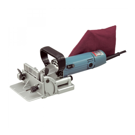
- Page 1 Plate Joiner MODEL 3901 004573 DOUBLE INSULATION I N S T R U C T I O N M A N U A L WARNING: For your personal safety, READ and UNDERSTAND before using. SAVE THESE INSTRUCTIONS FOR FUTURE REFERENCE.
-
Page 2: Specifications
Director have reached the end of their life MAKITA INTERNATIONAL EUROPE LTD. must be collected separately and Michigan Drive, Tongwell, Milton Keynes, Bucks MK15 returned to an environmentally com- 8JD, ENGLAND patible recycling facility. -
Page 3: Safety Instructions
SAFETY INSTRUCTIONS ENA001-2 WARNING: When using electric tools, basic safety precautions, including the following, should always be followed to reduce the risk of fire, electric shock and personal injury. Read all these instructions before operating this product and save these instructions. For safe operations: tion and changing accessories. -
Page 4: Additional Safety Rules
ADDITIONAL SAFETY RULES ENB060-2 Hold tool by insulated gripping surfaces when Secure the workpieces firmly with clamp or vise. performing an operation where the cutting tool 10. Never wear gloves during operation. may contact hidden wiring or its own cord. Con- 11. -
Page 5: Functional Description
FUNCTIONAL CAUTION: DESCRIPTION • Always be sure that the tool is switched off and unplugged before adjusting or checking function on the tool. Adjusting the depth of cut 004574 6 cutting depths can be preset according to the size of biscuit to be used or if trimming the wall or ceiling panels as explained later. - Page 6 Fence 004577 The angle of the fence can be adjusted between 0° and 90° (positive stops at 0°, 45° and 90°). To adjust the angle, loosen the lock lever and tilt the fence until the pointer points to the desired graduation on the angle scale. Then tighten the lock lever to secure the fence.
- Page 7 Set plate 004579 Use the set plate as shown in the figures when cutting slots in thin workpieces. 10 mm (0.4”) 6 mm (1/4”) 10 mm (0.4”) 1. Lock lever 2. Pointer 3. Angle scale 4. Set plate 5. Thickness of set plate 6.
- Page 8 4. Clamp screw 5. Blade cover CAUTION: • Use only Makita lock nut wrench provided to remove or install the blade. • Always check the depth of cut after replacing the blade. Reajust it if necessary. Dust bag 004583 To attach the dust bag, fit it onto the dust nozzle.
-
Page 9: Operation
OPERATION How to make joints 004584 To make joints, proceed as follows: Fig. A Fit the two workpieces together as they will appear in the finished joint position. Corner Joint (Fig. A) T-Butt Joint (Fig. B) Miter Joint (Fig. C) Frame Joint (Fig. - Page 10 004588 Fig. E For Corner Joint and T-Butt Joint only 004589 Clamp the vertical workpiece to the workbench. For Miter Joint only 004590 Clamp one workpiece to the workbench with the mitered edge facing up. For Frame Joint and Edge-To-Edge Joint only 004591 Clamp one workpiece to the workbench.
- Page 11 Align the center mark on the base with the pencil line on the workpiece. 004593 Switch on the tool and gently push it forward to extend the blade into the workpiece. Gently return the tool to the original position after the adjusting screw reaches the stopper.
- Page 12 For Frame Joint and Edge-To-Edge Joint only 004597 Clamp the other workpiece to the workbench. 1. For Frame Joint 004598 1. For Edge-To-Edge Joint 10. For Corner Joint only 004599 Place the tool on the workpiece so that the blade is facing down. For T-Butt Joint only 004600 Remove the angle guide from the tool.
- Page 13 For T-Butt Joint only 004602 • Fit the two workpieces together as they will appear in the finished joint position. • Lay the vertical workpiece on the horizontal one. Clamp both workpieces to the workbench. • Remove the angle guide from the tool. •...
-
Page 14: Maintenance
To maintain product SAFETY and RELIABILITY, repairs, any other mainte- nance or adjustment should be performed by Makita Authorized or Factory Service Centers, always using Makita replacement parts. 1. Brush holder cap... - Page 15 CAUTION: • These accessories or attachments are recommended for use with your Makita tool specified in this manual. The use of any other accessories or attachments might present a risk of injury to persons. Only use accessory or attachment for its stated purpose.
- Page 16 Makita Corporation Anjo, Aichi, Japan 883857B228...
Need help?
Do you have a question about the 3901 and is the answer not in the manual?
Questions and answers