
Related Manuals for Cebora POWER ROD 1565


Summary of Contents for Cebora POWER ROD 1565
- Page 1 CEBORA S.p.A. POWER ROD 1565 POWER SOURCE art. 253 SERVICE MANUAL 3.302.107 12/11/02...
-
Page 2: Table Of Contents
CEBORA S.p.A. CONTENTS - GENERAL INFORMATION.......................... 3 - Introduction..............................3 - General service policy..........................3 - Safety information............................3 - Electromagnetic compatibility........................3 - SYSTEM DESCRIPTION ..........................4 - Introduction..............................4 - Technical specifications..........................4 - Description of power source art. 253......................4 - MAINTENANCE............................ -
Page 3: General Information
It is forbidden to attempt to repair damaged electronic boards or modules; replace them with original Cebora spare parts. 1.3 - Safety information. The safety notes provided in this manual are an integral part of those given in the Instruction Manual. -
Page 4: System Description
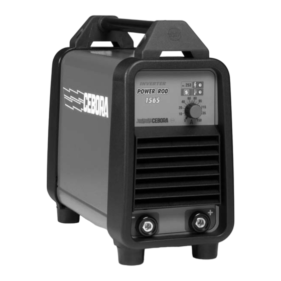
2 - SYSTEM DESCRIPTION 2.1 - Introduction. The POWER ROD 1565 is a MMA and TIG welding system, with contact arc starting mode. It is made up of an electronic power source (art. 253), and a set of accessories to adapt to various applications (see list in Sales Catalogue). -
Page 5: Maintenance
CEBORA S.p.A. 3 - MAINTENANCE WARNINGS ANY INTERNAL INSPECTIONS OR REPAIRS MUST BE CARRIED OUT BY QUALIFIED PERSONNEL. BEFORE BEGINNING MAINTENANCE OPERATIONS, UNPLUG THE MACHINE FROM THE MAINS AND WAIT FOR THE INTERNAL CAPACITORS TO DISCHARGE (3 MINUTES). 3.1 - Periodic inspection, cleaning. -
Page 6: Starting The Power Source
In TIG, connect the TIG torch (suggested torch T150, art. 1567.01 Cebora) to the negative pole of the power source and the cable of the positive pole of the power source to the workpiece. -
Page 7: Troubleshooting
CEBORA S.p.A. 3.3 - Troubleshooting. WARNINGS ANY INTERNAL INSPECTIONS OR REPAIRS MUST BE CARRIED OUT BY QUALIFIED PERSONNEL. BEFORE REMOVING THE PROTECTIVE GUARDS AND ACCESSING INTERNAL PARTS, DISCONNECT THE POWER SOURCE FROM THE MAINS AND WAIT FOR THE INTERNAL CAPACITORS TO DISCHARGE (3 MINUTES). -
Page 8: Power Source Powered, Fan (9) Stopped
CEBORA S.p.A. 3.3.2 - Power source powered, fan (9) stopped. FAN TEST. Fast-on terminals fan (9) = 230 Vac, with switch (5) closed. Correct? ♦ Make sure that there are no mechanical impediments blocking the fan. ♦ Replace the fan (9). -
Page 9: In Open Circuit Operation, The Output Voltage Is Not Regular
CEBORA S.p.A. 3.3.4 - In open circuit operation, the output voltage is not regular. OPEN-CIRCUIT OUTPUT VOLTAGE TEST. Output terminal – power source (-) and output terminal + power source (+) = +80 Vdc approximately, after “lamp-test” phase. Correct? ♦ Check the connection between the “-” and “+” terminals on the power board (13), and “-”... -
Page 10: In Tig, Arc Unstable, Welding Irregular
CEBORA S.p.A. 3.3.6 - In TIG, arc unstable, welding irregular. NOTE In TIG, the welding quality may not be acceptable due to current instability. In this case we recommend switching to MMA operation, and performing welding tests. WELDING QUALITY TEST IN MMA. -
Page 11: Error Codes
CEBORA S.p.A. 3.4 - Error codes. 3.4.1 - Yellow led (B) lit, with fix light. Alarm for temperature above limits. The thermostat is located on the dissipater of the power mosfets of the power board (13). The power source delivers no current, but the fan remains in operation; we therefore recommend leaving the power source powered in case of alarm for overtemperature. -
Page 12: Components List
CEBORA S.p.A. 4 - COMPONENTS LIST 4.1 - Power source art. 253: see file ESP253.pdf enclosed at the end of the manual. 4.2 - Components table: see file ESP253.pdf enclosed at the end of the manual. 4.3 - Spare parts list. - Page 13 CEBORA S.p.A. 5.2.2 - Topographical drawing. 3.302.107 12/11/02...
- Page 15 DESCRIZIONE DESCRIPTION DESCRIZIONE DESCRIPTION SUPPORTO MANICO HANDLE SUPPORT PANNELLO ANTERIORE FRONT PANEL MANICO HANDLE MANOPOLA KNOB FASCIONE HOUSING CORNICE FRAME COPERTURA IN GOMMA RUBBER MAT PRESA SOCKET INTERRUTTORE SWITCH CIRCUITO CONNETTORE CONNECTOR CIRCUIT PRESSACAVO STRAIN RELIEF SUPPORTO SUPPORT PANNELLO POSTERIORE BACK PANEL RETE METALLICA WIRE NETTING...
Need help?
Do you have a question about the POWER ROD 1565 and is the answer not in the manual?
Questions and answers