
Related Manuals for Cebora PLASMA PROF 55


Summary of Contents for Cebora PLASMA PROF 55
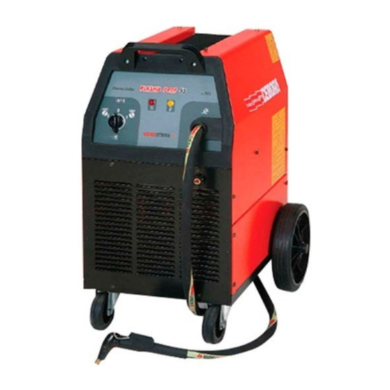
- Page 1 CEBORA S.p.A. PLASMA PROF 55 POWER SOURCE art. 965 SERVICE MANUAL 3.302.173 28/07/04...
-
Page 2: Table Of Contents
CEBORA S.p.A. CONTENTS - GENERAL INFORMATION......................3 - Introduction............................3 - General service policy........................3 - Safety information..........................3 - Electromagnetic compatibility.......................3 - SYSTEM DESCRIPTION........................4 - Introduction............................4 - Technical specifications.........................4 - Description of power source art. 965.....................4 - MAINTENANCE ..........................6 - Periodic inspection, cleaning. -
Page 3: General Information
It is forbidden to attempt to repair damaged electronic boards or modules; replace them with original Cebora spare parts. 1.3 - Safety information. The safety notes provided in this manual are an integral part of those given in the Instruction Manual. -
Page 4: System Description
CEBORA S.p.A. 2 - SYSTEM DESCRIPTION 2.1 - Introduction. The PLASMA PROF 55 is a system for cutting electrically conductive materials, using a plasma arc process. It is made up of an electronic power source (art. 965), with built-in torch. - Page 5 CEBORA S.p.A. When the start button is pressed, the control board (6) strikes the pilot arc by activating the solenoid valve EL1 (34) (the one with the flow reducer), the input contactor TLP (30) and high frequency generation. When solenoid valve EL1 (34) is opened, the gas starts to flow out from the torch for the pressure on the start button lasting time plus the post-gas time (90 seconds).
-
Page 6: Maintenance
CEBORA S.p.A. 3 - MAINTENANCE WARNINGS ANY INTERNAL INSPECTIONS OR REPAIRS MUST BE CARRIED OUT BY QUALIFIED PERSONNEL. DISCONNECT THE POWER SOURCE FROM THE MAINS BEFORE PERFORMING MAINTENANCE. 3.1 - Periodic inspection, cleaning. Periodically remove dirt and dust from the internal parts of the power source, using a jet of low-pressure dry compressed air or a brush. -
Page 7: Power Source Operation
CEBORA S.p.A. 3.2.2 - Power source operation. System shut off and unplugged from the mains. Connect the gas intake to the fitting (B) on the rear panel. Turn the gas setting knob (E) to a pressure, as read on the pressure gauge (F), suited to the type of torch being used (see Instruction Manual). -
Page 8: Troubleshooting
CEBORA S.p.A. 3.3 - Troubleshooting. WARNINGS ANY INTERNAL INSPECTIONS OR REPAIRS MUST BE CARRIED OUT BY QUALIFIED PERSONNEL. BEFORE REMOVING THE PROTECTIVE GUARDS AND ACCESSING INTERNAL PARTS, DISCONNECT THE POWER SOURCE FROM THE MAINS. NOTE Items in boldface describe problems that may occur on the machine (symptoms). -
Page 9: Power Source Powered, Lamp (38) Lit, Fan (39) Stopped
CEBORA S.p.A. Correct? ♦ Check the wiring between switch (29) and control board (6). ♦ Check integrity of fuses on control board (6), considering that: - F1 is inserted in the supply circuit for torch start button insulated circuit. For checking performs START COMMAND TEST, par. 3.3.3. -
Page 10: The Start Button Produces No Effect
CEBORA S.p.A. 3.3.3 - The start button produces no effect. START COMMAND TEST. Control board (6), connector J3, terminals 1 and 2 = approximately 24 Vac, with start button on torch released; approximately 0 Vac, (contact closed) with button pressed. -
Page 11: No Gas Flows From The Torch
CEBORA S.p.A. 3.3.4 - No gas flows from the torch. PILOT ARC SOLENOID VALVE EL1 (34) TEST. Solenoid valve EL1 (34) terminals = approximately 230 Vac, with torch button pressed. The solenoid valve opening time also depends on the post-gas time. -
Page 12: Gas Flows From The Torch, The Pilot Arc Does Not Light (High Frequency Missing)
CEBORA S.p.A. 3.3.5 - Gas flows from the torch, the pilot arc does not light (high frequency missing). HF OSCILLATOR TEST. Control board (6), discharger SCI1 discharges at regular intervals, for approximately 300 msec. (HF generation time) with start button pressed. -
Page 13: Gas Flows From The Torch, The Pilot Arc Does Not Light (Nozzle Voltage Missing)
CEBORA S.p.A. 3.3.6 - Gas flows from the torch, the pilot arc does not light (nozzle voltage missing). WARNING FOR THE FOLLOWING TESTS DISCONNECT TERMINALS J5 AND J6 ON CONTROL BOARD (6) TO PREVENT HIGH FREQUENCY FROM BEING GENERATED. POWER SOURCE OUTPUT VOLTAGE TEST. -
Page 14: In Open Circuit Operation, The Output Voltage Is Not Regular
CEBORA S.p.A. 3.3.7 - In open circuit operation, the output voltage is not regular. WARNING FOR THE FOLLOWING TESTS DISCONNECT TERMINALS J5 AND J6 ON CONTROL BOARD (6) TO PREVENT HIGH FREQUENCY FROM BEING GENERATED. POWER SOURCE OUTPUT VOLTAGE TEST. -
Page 15: Irregular Pilot Arc Starts, Unstable Pilot Arc
CEBORA S.p.A. 3.3.8 - Irregular pilot arc starts, unstable pilot arc. PLASMA GAS PRESSURE TEST. Gas pressure correct in the plasma chamber of the torch. Correct? ♦ Check for the presence of gas at the intake fitting (B) and make sure that the pressure and flow rate in the intake line meet specifications. -
Page 16: Transfer Arc Does Not Take Place Or Is Too Weak For Cutting
CEBORA S.p.A. 3.3.9 - Transfer arc does not take place or is too weak for cutting. PILOT ARC OPERATING TEST. Pilot arc lights normally, pilot arc stable. Correct? ♦ Go to par. 3.3.8. TRANSFER ARC SWITCHING TEST. Control board (6), connector J2, terminals 1 and 2 = 0 Vac, reed contact closed, with transfer arc, thus while cutting (24 Vac reed contact opened, with pilot arc on). -
Page 17: Alarm Signals
CEBORA S.p.A. 3.4 - Alarm signals. 3.4.1 - Lamp (G) (45) lit, with fix light = transformer (44) temperature above the limit. Power source remains in block with contactor TLP (30) opened. We recommend not to shut off the power source, to keep the fan (39) running and thus allow rapid cooling. -
Page 18: Lamp (L) (45) Lit, With Fix Light = Low Gas Pressure
CEBORA S.p.A. 3.4.4 - Lamp (L) (45) lit, with fix light = low gas pressure. With this alarm the power source remains in block with contactor TLP (30) opened, without output voltage. This is automatically reset when the pressure returns within the allowed limits, but to restart pilot arc you need a new start command by torch start button. -
Page 19: Components List
CEBORA S.p.A. 4 - COMPONENTS LIST 4.1 - Power source art. 965 : see file ESP965.pdf enclosed at the end of the manual. 4.2 - Components table: see file ESP965.pdf enclosed at the end of the manual. 4.3 - List of spare parts. -
Page 20: Electrical Diagrams
CEBORA S.p.A. 5 - ELECTRICAL DIAGRAMS 5.1 - Power source art. 965 : see file SCHE965.pdf enclosed at the end of the manual. 5.2 - Control board (6) code 5.602.170. 5.2.1 - Topographical drawing. 5.2.2 - Connector table. Connector Terminals... -
Page 21: Hf-Filter Board (47) Code 5.602.173
CEBORA S.p.A. 5.3 - HF-filter board (47) code 5.602.173. 5.3.1 - Topographical drawing. 5.3.2 - Connector table. Connector Terminals Function A - B start signal input. A - B start signal output. output voltage input (workpiece potential). TP4 - TP7 rectifier (32) output voltage input. - Page 23 DESCRIZIONE DESCRIPTION DESCRIZIONE DESCRIPTION TRASFORMATORE H.F. H.F. TRANSFORMER LATERALE DESTRO RIGHT SIDE PANEL COPERCHIO COVER RADDRIZZATORE RECTIFIER COPERTURA GOMMA RUBBER MAT PRESSOSTATO PRESSURE SWITCH LATERALE FISSO FIXED SIDE PANEL ELETTROVALVOLA SOLENOID VALVE PIANO INTERMEDIO INSIDE BAFFLE CONTATTO CONTACT SERRAPACCO PACK HOLDER CIRCUITO DI CONTROLLO CONTROL CIRCUIT PANNELLO POSTERIORE...
Need help?
Do you have a question about the PLASMA PROF 55 and is the answer not in the manual?
Questions and answers