Table of Contents
Advertisement
Quick Links
Quick Start
Thank you for purchasing the MSI®
section provides demonstration diagrams about how to install your computer. Some
of the installations also provide video demonstrations. Please link to the URL to watch
it with the web browser on your phone or tablet. You may have even link to the URL by
scanning the QR code.
Preparing Tools and Components
Intel® LGA 1200 CPU
DDR4 Memory
Thermal Paste
Phillips Screwdriver
MEG Z590I UNIFY
CPU Fan
Power Supply Unit
SATA Hard Disk Drive
motherboard. This Quick Start
Graphics Card
SATA DVD Drive
A Package of Screws
Chassis
1
Quick Start
Advertisement
Table of Contents

Related Manuals for MSI MEG Z590I UNIFY


Summary of Contents for MSI MEG Z590I UNIFY
-
Page 1: Quick Start
Quick Start Thank you for purchasing the MSI® MEG Z590I UNIFY motherboard. This Quick Start section provides demonstration diagrams about how to install your computer. Some of the installations also provide video demonstrations. Please link to the URL to watch it with the web browser on your phone or tablet. -
Page 2: Safety Information
Safety Information ∙ The components included in this package are prone to damage from electrostatic discharge (ESD). Please adhere to the following instructions to ensure successful computer assembly. ∙ Ensure that all components are securely connected. Loose connections may cause the computer to not recognize a component or fail to start. -
Page 3: Installing A Processor
Installing a Processor ⚽ https://youtu.be/4ce91YC3Oww Quick Start... -
Page 4: Installing Ddr4 Memory
Installing DDR4 memory ⚽ http://youtu.be/T03aDrJPyQs DIMMA1 DIMMB1 DIMMB1 Quick Start... -
Page 5: Connecting The Front Panel Header
Connecting the Front Panel Header ⚽ http://youtu.be/DPELIdVNZUI Power LED Power Switch JFP1 Reserved HDD LED Reset Switch HDD LED + Power LED + HDD LED - Power LED - Reset Switch Power Switch JFP1 Reset Switch Power Switch Reserved No Pin HDD LED - HDD LED HDD LED +... -
Page 6: Installing The Motherboard
Installing the Motherboard ⚽ https://youtu.be/wWI6Qt51Wnc Torque: 3 kgf·cm* *3 kgf·cm = 0.3 N·m = 2.6 lbf·in Quick Start... -
Page 7: Connecting The Power Connectors
Connecting the Power Connectors ⚽ http://youtu.be/gkDYyR_83I4 ATX_PWR1 CPU_PWR1 Quick Start... -
Page 8: Installing Sata Drives
Installing SATA Drives ⚽ http://youtu.be/RZsMpqxythc Quick Start... -
Page 9: Installing A Graphics Card
Installing a Graphics Card ⚽ http://youtu.be/mG0GZpr9w_A Quick Start... -
Page 10: Connecting Peripheral Devices
Connecting Peripheral Devices Quick Start... -
Page 11: Power On
Power On Quick Start... -
Page 12: Table Of Contents
JTPM1: TPM Module Connector ................37 CPU_FAN1, PUMP_FAN1, SYS_FAN1: Fan Connectors ........38 JCI1: Chassis Intrusion Connector ............... 39 EZ Debug LED ....................... 39 JRAINBOW1: Addressable RGB LED connector ..........40 Installing OS, Drivers & MSI Center ..............41 Contents... - Page 13 Installing Windows® 10 ..................41 Installing Drivers ....................41 MSI Center ......................41 UEFI BIOS ......................42 BIOS Setup ......................43 Entering BIOS Setup ..................... 43 BIOS User Guide ....................43 Resetting BIOS ...................... 44 Updating BIOS ....................... 44 RAID Configuration ....................46 Intel®...
-
Page 14: Specifications
∙ Supports Dual-Channel mode ∙ Supports non-ECC, un-buffered memory ∙ Supports Intel® Extreme Memory Profile (XMP) *Please refer www.msi.com for more information on compatible memory ∙ 1x PCIe x16 slot Expansion Slot ▪ Support up to PCIe 4.0 for 11th Gen Intel® CPU ▪... - Page 15 * SATA2 will be unavailable when installing M.2 SATA SSD in the M2_1 slot. ** Before using Intel® Optane™ memory modules, please ensure that you have updated the drivers and BIOS to the latest version from MSI website. ∙ Supports RAID 0, RAID 1, RAID 5 and RAID 10 for SATA...
- Page 16 Continued from previous column ∙ Intel® Z590 Chipset ▪ 3x USB 3.2 Gen 2 10Gbps ports (2 Type-A port on the back panel, 1 Type-C internal connector) ▪ 4x USB 3.2 Gen 1 5Gbps ports (2 Type-A ports on the back panel, 2 ports available through the internal USB connectors) ▪...
- Page 17 Continued from previous column ∙ 1x 24-pin ATX main power connector ∙ 1x 8-pin ATX 12V power connector ∙ 4x SATA 6Gb/s connectors ∙ 2x M.2 slots (M-Key) ∙ 1x USB 3.2 Gen 2 10Gbps Type-C port ∙ 1x USB 3.2 Gen 1 5Gbps connector (supports additional 2 USB 3.2 Gen 1 5Gbps ports) ∙...
- Page 18 ∙ Drivers ∙ MSI Center ∙ Intel Extreme Tuning Utility ∙ Nahimic Audio Software ∙ MSI APP Play (Bluestack) ∙ Open Broadcaster Software (OBS) ∙ CPU-Z MSI GAMING ∙ Google Chrome™, Google Toolbar, Google Drive ∙ Norton™ Internet Security Solution ∙...
- Page 19 Continued from previous column ∙ Audio ▪ Audio Boost4 ▪ Nahimic 3 ▪ Sound Tune ∙ Network ▪ 2.5G LAN ▪ LAN Manager ▪ Intel WiFi ∙ Cooling ▪ Frozr Heatsink Design ▪ All Aluminum Design ▪ Extended Heatsink Design Special Features ▪...
- Page 20 ▪ Front USB Type-C ▪ Server PCB ▪ 2oz Copper thickened PCB ∙ Protection ▪ PCI-E Steel Armor ▪ Pre-installed I/O Shield ∙ Experience ▪ MSI Center ▪ Duet Display ▪ Frozr AI Cooling ▪ Click BIOS 5 ▪ Clear CMOS Button Specifications...
-
Page 21: Package Contents
Package contents Please check the contents of your motherboard package. It should contain: Motherboard MEG Z590I UNIFY User manual Documentation Quick guide Quick installation guide Application USB drive with drivers & utilities SATA 6Gb/s cables Cables LED JRAINBOW cable DP to Mini-DP cable... -
Page 22: Block Diagram
Block Diagram PCI_E1 PCIe x16 M2_1 DDR4 2Channel DIMM A1 HDMI DIMM B1 DMI x8 USB 3.2 Gen 2 10Gbps M2_1 USB 3.2 Gen 1 5Gbps M2_2 USB 2.0 Thunderbolt Intel LAN I225 SATA1/2/3/4 WiFi AX210 HD Audio SIO 6687 ALC1220 Block Diagram... -
Page 23: Rear I/O Panel
Rear I/O Panel Line Out 2.5 Gbps LAN Thunderbolt 4 Line In (USB-C) USB 2.0 DisplayPort Wi-Fi Antenna Mic In Clear CMOS USB 3.2 Gen 1 connectors button 5Gbps Type A USB 3.2 Gen 2 Mini DisplayPort 10Gbps Type A Input (for Thunderbolt passthrough) ∙... -
Page 24: Installing Antennas
Installing Antennas 1. Combine the antenna with the base. 2. Screw two antenna cables tight to the WiFi antenna connectors as shown. 3. Place the antenna as high as possible. Rear I/O Panel... -
Page 25: Connecting Thunderbolt Devices Via Daisy-Chain
Connecting Thunderbolt Devices via Daisy-chain Daisy-chain is a method of connecting multiple devices to a PC with only one output terminal. Daisy-chain allows you to connect multiple thunderbolt devices to a single thunderbolt port on the back panel. You can also daisy chain monitor by connecting graphics card to the Mini DisplayPort Input port on the back panel. -
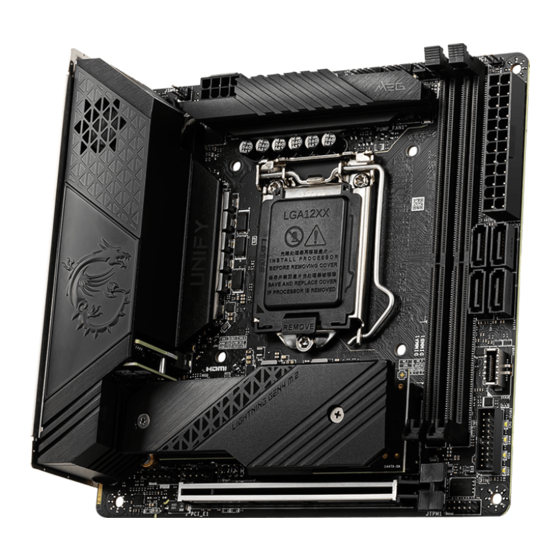
Page 26: Overview Of Components
Overview of Components CPU_FAN1 Processor PUMP_FAN1 Socket SYS_FAN1 DIMMA1 CPU_PWR1 JRAINBOW1 DIMMB1 JCI1 ATX_PWR1 SATA3 SATA1 SATA4 SATA2 JUSB3 JFP2 M2_1 JUSB2 PCI_E1 JTPM1 JUSB1 JAUD1 JFP1 M2_2 Overview of Components... - Page 27 Component Contents Port Name Port Type Page CPU_FAN1, PUMP_FAN1, Fan Connectors SYS_FAN1 CPU_PWR1, ATX_PWR1 Power Connectors CPU Socket LGA1200 CPU Socket DIMM Slots Memory slots JAUD1 Front Audio Connector JCI1 Chassis Intrusion Connector JFP1, JFP2 Front Panel Connectors JRAINBOW1 Addressable RGB LED connector JTPM1 TPM Module Connector JUSB1...
-
Page 28: Cpu Socket
∙ the CPU. ∙ Please retain the CPU protective cap after installing the processor. MSI will deal with Return Merchandise Authorization (RMA) requests if only the motherboard comes with the protective cap on the CPU socket. When installing a CPU, always remember to install a CPU heatsink. A CPU heatsink ∙... -
Page 29: Dimm Slots
It is recommended to use a more efficient memory cooling system for full DIMMs ∙ installation or overclocking. The stability and compatibility of installed memory module depend on installed CPU ∙ and devices when overclocking. ∙ Please refer to www.msi.com for more information on compatible memory. Overview of Components... -
Page 30: Pci_E1: Pcie Expansion Slot
PCI_E1: PCIe Expansion Slot ⚠ Important If you install a large and heavy graphics card, you need to use a tool such as MSI ∙ Graphics Card Bolster to support its weight to prevent deformation of the slot. When adding or removing expansion cards, always turn off the power supply and ∙... -
Page 31: M2_1~2: M.2 Slots (Key M)
M2_1~2: M.2 Slots (Key M) ⚽ Video Demonstration Watch the video to learn how to Install M.2 SSD. https://youtu.be/2UeWMgjwogU M2_1 M2_2 ⚠ Important Intel® RST only supports PCIe M.2 SSD with UEFI ROM. ∙ Intel® Optane™ Memory Ready. ∙ Installing M.2 module For M2_1 slot: 1. - Page 32 4. Put the M.2 SHIELD FROZR heatsink back in place and secure it. For M2_2 slot: 1. Loosen the screws of M.2 SHIELD FROZR heatsink and remove the heatsink. 2. Loosen the screws of M.2 adapter card. 3. Pull out the M.2 adapter card. Overview of Components...
- Page 33 4. Turn the M.2 adapter card over and place the M2_2 slot up. 5. Insert your M.2 SSD into the M2_2 slot at a 30-degree angle. 6. Secure the M.2 SSD in place with the supplied M.2 8.5H screw. 30º 30º...
-
Page 34: Jfp1, Jfp2: Front Panel Connectors
JFP1, JFP2: Front Panel Connectors These connectors connect to the switches and LEDs on the front panel. Buzzer JFP2 Speaker Speaker - Buzzer + Buzzer - Speaker + Power LED Power Switch JFP1 Reserved HDD LED Reset Switch HDD LED + Power LED + HDD LED - Power LED -... -
Page 35: Cpu_Pwr1, Atx_Pwr1: Power Connectors
CPU_PWR1, ATX_PWR1: Power Connectors These connectors allow you to connect an ATX power supply. CPU_PWR1 Ground +12V Ground +12V Ground +12V Ground +12V +3.3V +3.3V +3.3V -12V Ground Ground PS-ON# Ground Ground Ground ATX_PWR1 Ground Ground PWR OK 5VSB +12V +12V +3.3V Ground... -
Page 36: Jusb2: Usb 3.2 Gen 1 Connector
JUSB2: USB 3.2 Gen 1 Connector These connectors allow you to connect USB 3.2 Gen 1 5Gbps ports on the front panel. Power USB2.0+ USB3_RX_DN USB2.0- USB3_RX_DP Ground Ground USB3_TX_C_DP USB3_TX_C_DN USB3_TX_C_DN USB3_TX_C_DP Ground Ground USB3_RX_DP USB2.0- USB3_RX_DN USB2.0+ Power Ground No Pin ⚠... -
Page 37: Jusb1: Usb 2.0 Connector
In order to recharge your iPad, iPhone and iPod through USB ports, please install ∙ MSI Center utility. JTPM1: TPM Module Connector This connector is for TPM (Trusted Platform Module). Please refer to the TPM security platform manual for more details and usages. -
Page 38: Cpu_Fan1, Pump_Fan1, Sys_Fan1: Fan Connectors
CPU_FAN1, PUMP_FAN1, SYS_FAN1: Fan Connectors Fan connectors can be classified as PWM (Pulse Width Modulation) Mode or DC Mode. PWM Mode fan connectors provide constant 12V output and adjust fan speed with speed control signal. DC Mode fan connectors control fan speed by changing voltage. The auto mode fan connectors can automatically detect PWM and DC mode. -
Page 39: Jci1: Chassis Intrusion Connector
JCI1: Chassis Intrusion Connector This connector allows you to connect the chassis intrusion switch cable. Normal Trigger the chassis (default) intrusion event Using chassis intrusion detector 1. Connect the JCI1 connector to the chassis intrusion switch/ sensor on the chassis. 2. -
Page 40: Jrainbow1: Addressable Rgb Led Connector
(5V). In the case of 20% brightness, the connector supports up to 200 LEDs. ∙ Always turn off the power supply and unplug the power cord from the power outlet before installing or removing the RGB LED strip. ∙ Please use MSI’s software to control the extended LED strip. Overview of Components... -
Page 41: Installing Os, Drivers & Msi Center
MSI Center is an application that helps you easily optimize game settings and smoothly use content creation softwares. It also allows you to control and synchronize LED light effects on PCs and other MSI products. With MSI Center, you can customize ideal modes, monitor system performance, and adjust fan speed. -
Page 42: Uefi Bios
UEFI BIOS MSI UEFI BIOS is compatible with UEFI (Unified Extensible Firmware Interface) architecture. The UEFI BIOS firmware infrastructure has many new functions and advantages that traditional BIOS cannot achieve. It will fully support future PCs and devices that comply with UEFI firmware architecture. -
Page 43: Bios Setup
* When you press F10, a confirmation window appears and it provides the modification information. Select between Yes or No to confirm your choice. BIOS User Guide If you’d like to know more instructions on setting up the BIOS, please refer to http://download.msi.com/manual/mb/Intel500BIOS.pdf or scan the QR code to access. UEFI BIOS... -
Page 44: Resetting Bios
Updating BIOS Updating BIOS with M-FLASH Before updating: Please download the latest BIOS file that matches your motherboard model from MSI website. And then save the BIOS file into the USB flash drive. To update BIOS: 1. Insert the USB flash drive that contains the update file into the USB port. - Page 45 ∙ Please close all other application software before updating the BIOS. To update BIOS: 1. Install and launch MSI CENTER and go to Support page. 2. Select Live Update and click on the Advanced button. 3. Select the BIOS file and click on the Install button.
-
Page 46: Raid Configuration
All the information/ volumes/ pictures listed in your system might differ from the illustrations in this appendix. Intel RAID User Guide If you’d like to know more instructions on how to set up Intel RAID, please refer to http://download.msi.com/manual/mb/IntelRAID.pdf or scan the QR code to access. RAID Configuration... -
Page 47: Intel® Optane™ Memory Configuration
Optane™ memory, please note that it requires Windows 10 64-bit operating system. Intel® Optane™ Memory User Guide If you’d like to know more instructions on how to enable or remove Intel® Optane™ Memory, please refer to http://download.msi.com/manual/mb/Optane.pdf or scan the QR code to access. ⚠ WARNING After you enable Intel®... -
Page 48: Troubleshooting
Troubleshooting Lost BIOS password Before sending the motherboard for RMA repair, try to go over troubleshooting ∙ Clear the CMOS, but that will cause guide first to see if your got similar you to lose all customized settings in the symptoms as mentioned below. - Page 49 ∙ This device may not cause harmful interference. ∙ This device must accept any interference received, including interference that may cause undesired operation. MSI Computer Corp. 901 Canada Court, City of Industry, CA 91748, USA (626)913-0828 www.msi.com...
- Page 50 ∙ ErP Directive 2009/125/EC Compliance with these directives is assessed using applicable European Harmonized Standards. The point of contact for regulatory matters is MSI-Europe: Eindhoven 5706 5692 ER Son. Products with Radio Functionality (EMF) This product incorporates a radio transmitting and receiving device. For computers in normal use, a separation distance of 20 cm ensures that radio frequency exposure levels comply with EU requirements.
- Page 51 Wireless Radio Use This device is restricted to indoor use when operating in the 2.4GHz, 5GHz, 6GHz frequency band. Cet appareil doit être utilisé à l’intérieur. 당해 무선설비는 운용중 전파혼신 가능성이 있음. この製品は 、 周波数帯域 2.4GHz, 5GHz, 6GHz で動作しているときは 、 屋内においてのみ使 用可能です...
- Page 52 KC인증서 상호: (주)엠에스아이코리아 제품명: 메인보드 모델명: 10-7D05 제조년월: 2021년 R-R-MSI-10-7D05 제조자 및 제조국가: MSI/중국 상호: (주)엠에스아이코리아 제품명: USB FLASH DRIVE 모델명: USB2VR09 제조년월: 2023년 R-R-MSI-USB2VR09 제조자 및 제조국가: MSI/중국...
- Page 53 ∙ Users should contact the local authorized point of collection for recycling and disposing of their end-of-life products. ∙ Visit the MSI website and locate a nearby distributor for further recycling information. ∙ Users may also reach us at gpcontdev@msi.com for information regarding proper Disposal, Take-back, Recycling, and Disassembly of MSI products.
- Page 54 MSI will comply with the product take back requirements at the end of life of MSI- branded products that are sold into the EU. You can return these products to local collection points.
- Page 55 MSI će poštovati zahtev o preuzimanju ovakvih proizvoda kojima je istekao vek trajanja, koji imaju MSI oznaku i koji su prodati u EU. Ove proizvode možete vratiti na lokalnim mestima za prikupljanje.
- Page 56 MSI si adeguerà a tale Direttiva ritirando tutti i prodotti marchiati MSI che sono stati venduti all’interno dell’Unione Europea alla fine del loro ciclo di vita.
- Page 57 Việt Nam RoHS Kể từ ngày 01/12/2012, tất cả các sản phẩm do công ty MSI sản xuất tuân thủ Thông tư số 30/2011/TT-BCT quy định tạm thời về giới hạn hàm lượng cho phép của một số hóa chất độc hại có trong các sản phẩm điện, điện tử”...
- Page 58 Alternatively, please try the following help resources for further guidance. ∙ Visit the MSI website for technical guide, BIOS updates, driver updates, and other information: http://www.msi.com ∙ Register your product at: http://register.msi.com Revision History ∙...
Need help?
Do you have a question about the MEG Z590I UNIFY and is the answer not in the manual?
Questions and answers