
Related Manuals for Red-D-Arc Welderentals FieldPro EX 360


Summary of Contents for Red-D-Arc Welderentals FieldPro EX 360
- Page 1 OM-282358A 2018−03 Processes Multiprocess Welding Description Arc Welding Power Source ™ EX 360 FieldPro ™ With Auto-Line And ArcReach File: MULTIPROCESS Available for rent at reddarc.com...
- Page 2 Available for rent at reddarc.com...
-
Page 3: Table Of Contents
TABLE OF CONTENTS SECTION 1 − SAFETY PRECAUTIONS - READ BEFORE USING ....... . . 1-1. - Page 4 TABLE OF CONTENTS SECTION 8 − GMAW/FCAW OPERATION ............8-1.
-
Page 5: Section 1 − Safety Precautions - Read Before Using
SECTION 1 − SAFETY PRECAUTIONS - READ BEFORE USING som 2018−01 Protect yourself and others from injury — read, follow, and save these important safety precautions and operating instructions. 1-1. Symbol Usage DANGER! − Indicates a hazardous situation which, if Indicates special instructions. - Page 6 D Do not cut or weld on tire rims or wheels. Tires can explode if heat- FUMES AND GASES can be hazardous. ed. Repaired rims and wheels can fail. See OSHA 29 CFR 1910.177 listed in Safety Standards. D Do not weld on containers that have held combustibles, or on Welding produces fumes and gases.
-
Page 7: Additional Symbols For Installation, Operation, And Maintenance
D Never weld on a pressurized cylinder − explosion will result. CYLINDERS can explode if damaged. D Use only correct compressed gas cylinders, regulators, hoses, and fittings designed for the specific application; maintain them Compressed gas cylinders contain gas under high and associated parts in good condition. -
Page 8: California Proposition 65 Warnings
H.F. RADIATION can cause interference. ARC WELDING can cause interference. D High-frequency (H.F.) can interfere with radio D Electromagnetic energy can interfere with navigation, safety services, computers, and sensitive electronic equipment such as communications equipment. computers and computer-driven equipment such as robots. D Have only qualified persons familiar with electronic equipment D Be sure all equipment in the welding area is electromagnetically perform this installation. -
Page 9: Section 2 − Consignes De Sécurité − Lire Avant Utilisation
SECTION 2 − CONSIGNES DE SÉCURITÉ − LIRE AVANT UTILISATION som_2018−01_fre Pour écarter les risques de blessure pour vous−même et pour autrui — lire, appliquer et ranger en lieu sûr ces consignes relatives aux précautions de sécurité et au mode opératoire. 2-1. - Page 10 D Déplacer toutes les substances inflammables à une distance de LES PIÈCES CHAUDES peuvent 10,7 m de l’arc de soudage. En cas d’impossibilité les recouvrir provoquer des brûlures. soigneusement avec des protections homologués. D Ne pas toucher à mains nues les parties chaudes. D Ne pas souder dans un endroit là...
-
Page 11: Dangers Supplémentaires En Relation Avec L'installation, Le Fonctionnement Et La Maintenance
D Protéger les bouteilles de gaz comprimé d’une chaleur excessive, Les CHAMPS ÉLECTROMAGNÉTIQUES (CEM) des chocs mécaniques, des dommages physiques, du laitier, des peuvent affecter les implants médicaux. flammes ouvertes, des étincelles et des arcs. D Placer les bouteilles debout en les fixant dans un support station- D Les porteurs de stimulateurs cardiaques et naire ou dans un porte-bouteilles pour les empêcher de tomber ou autres implants médicaux doivent rester à... -
Page 12: Proposition Californienne 65 Avertissements
D Effectuer régulièrement le contrôle et l’entretien de l’installation. LIRE LES INSTRUCTIONS. D Maintenir soigneusement fermés les portes et les panneaux des sources de haute fréquence, maintenir les éclateurs à une distan- D Lire et appliquer les instructions sur les ce correcte et utiliser une terre et un blindage pour réduire les étiquettes et le Mode d’emploi avant l’instal- interférences éventuelles. -
Page 13: Section 3 − Definitions
SECTION 3 − DEFINITIONS 3-1. Additional Safety Symbols And Definitions Some symbols are found only on CE products. Warning! Watch Out! There are possible hazards as shown by the symbols. Safe1 2012−05 Do not discard product (where applicable) with general waste. Reuse or recycle Waste Electrical and Electronic Equipment (WEEE) by disposing at a designated collection facility. - Page 14 Welding sparks can cause fires. Have a fire extinguisher nearby, and have a watchperson ready to use it. Safe14 2012−05 Do not weld on drums or any closed containers. Safe16 2017−04 Do not remove or paint over (cover) the label. Safe20 2017−04 Flying pieces of parts can cause injury.
-
Page 15: Miscellaneous Symbols And Definitions
3-2. Miscellaneous Symbols And Definitions Amperage Three Phase Percent Negative Voltage Output Single Phase Variable Positive Inductance Gas Metal Arc Arc Force Remote Welding (GMAW) (DIG) Flux Cored Arc Flux Cored Arc Input Voltage Welding - Self Welding (FCAW) Shielded (FCAW-S) Shielded Metal Line Connection... -
Page 16: Section 4 − Specifications
SECTION 4 − SPECIFICATIONS 4-1. Features And Benefits LVCt Line Voltage Compensation is circuitry that keeps the power source output constant regardless of input pow- er fluctuation. Wind Tunnel Technologyt circulates air over components that require cooling, not over electronic circuitry, which reduces contaminants and improves reliability in harsh welding environments. -
Page 17: Dimensions And Weight
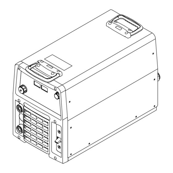
4-5. Dimensions And Weight Hole Layout Dimensions 12.875 in. (327 mm) 25.25 in. (641 mm) 4.687 in. (119 mm) 17.312 in. (440 mm) 15.75 in. (400 mm) 22.093 in. (561 mm) 12.75 in. (324 mm) 8.687 in. (221 mm) 1.531 in. (39 mm) 278579-A 278673-A 1.687 in. -
Page 18: Duty Cycle And Overheating
4-7. Duty Cycle And Overheating Duty Cycle is percentage of 10 minutes that unit can weld at rated load without overheating. If unit overheats, output stops, a Help message is dis- played and cooling fan runs. Wait fifteen minutes for unit to cool. -
Page 19: Volt-Ampere Curves
4-8. Volt-Ampere Curves Volt-ampere curves show minimum A. CC Mode and maximum voltage and amper- age output capabilities of welding power source. Curves of other set- tings fall between curves shown. SMAW GTAW SMAW GTAW CONTROL 100% AMPERAGE B. CV Mode 5 00 AMPERAGE 217 836-A / 217 837-B... -
Page 20: Section 5 − Installation
SECTION 5 − INSTALLATION 5-1. Selecting A Location Movement Do not move or operate unit where it could tip. Location And Airflow Special installation may be required where gasoline or volatile liquids are present − see NEC Article 511 or CEC Section 20. -
Page 21: Selecting Cable Sizes
5-2. Selecting Cable Sizes* NOTICE − The Total Cable Length in Weld Circuit (see table below) is the combined length of both weld cables. For example, if the power source is 100 ft (30 m) from the workpiece, the total cable length in the weld circuit is 200 ft (2 cables x 100 ft). Use the 200 ft (60 m) column to determine cable size. -
Page 22: Remote 14 Receptacle Information
5-4. Remote 14 Receptacle Information Socket* Socket Information 24 volts AC. Protected by supplementary protect- or CB2. 24 VOLTS AC Contact closure to A completes 24 volts AC C L N contactor control circuit. Output to remote control; 0 to +10 volts DC, +10 volts DC in MIG mode. -
Page 23: Optional Gas Valve Operation And Shielding Gas Connection
5-6. Optional Gas Valve Operation And Shielding Gas Connection Obtain gas cylinder and chain to running gear, wall, or other station- ary support so cylinder cannot fall and break off valve. Cylinder Regulator/Flowmeter Install so face is vertical. Gas Hose Connection Fitting has 5/8-18 right-hand... -
Page 24: Electrical Service Guide
5-7. Electrical Service Guide Elec Serv 2017-01 NOTICE − INCORRECT INPUT POWER can damage this welding power source. This welding power source requires a CONTINUOUS supply of input power at rated frequency(+10%) and voltage (+10%). Phase to ground voltage shall not exceed +10% of rated input voltage. Do not use a genera- tor with automatic idle device (that idles engine when no load is sensed) to supply input power to this welding power source. - Page 25 Notes Available for rent at reddarc.com OM-282358 Page 21...
-
Page 26: Connecting 1-Phase Input Power
5-8. Connecting 1-Phase Input Power =GND/PE Earth Ground Tools Needed: Input1 2012−05 − Ref. 803766-C / 278673-A Available for rent at reddarc.com OM-282358 Page 22... - Page 27 5-8. Connecting 1-Phase Input Power (Continued) nected to any input power between 208 and Disconnect Device (switch shown in the Installation must meet all National and 575 VAC without removing cover to relink the OFF position) Local Codes − have only qualified per- power source.
-
Page 28: Connecting 3-Phase Input Power
5-9. Connecting 3-Phase Input Power = GND/PE Earth Ground Tools Needed: input2 2012−05 − Ref. 803766-C / 278673-A Available for rent at reddarc.com OM-282358 Page 24... - Page 29 5-9. Connecting 3-Phase Input Power (Continued) voltage available at site. This unit can be con- Input Conductors (L1, L2 And L3) Installation must meet all National and nected to any input power between 208 and Local Codes − have only qualified per- Disconnect Device Line Terminals 575 VAC without removing cover to relink the sons make this installation.
-
Page 30: Section 6 − Operation
SECTION 6 − OPERATION 6-1. Front Panel Controls Ref. 278547-B / Ref. 278649-B values after arc initiation and remains dis- 10 Arc Control Stiff Indicator Weld process operation sections de- played for approximately three seconds 11 Arc Control Soft Indicator scribe functionality of the identified items after the arc is broken. -
Page 31: Mode Switch Settings
6-2. Mode Switch Settings Remote 14 Switch Position Process Output Control Panel Adjust ArcReach Adjust Adjust GMAW WIRE − Gas Remote 14 Volts Volts − − FCAW GMAW WIRE − Gas (1) Electrode Hot Volts Volts Volts FCAW WIRE - No Gas (1) FCAW-S Electrode Hot Volts... -
Page 32: Section 7 − Gtaw Operation
SECTION 7 − GTAW OPERATION 7-1. Typical Connection For GTAW Process 278669-A Remote 14 Receptacle Gas Out Connection (Optional) Turn off power before making con- nections. Connect desired remote control to Remote Negative (−) Weld Output Terminal 14 receptacle if required. Foot Control TIG Torch Gas In Connection (Optional) -
Page 33: Typical Connection For Arcreach Stick/Tig Remote (Gtaw Process)
7-2. Typical Connection For ArcReach Stick/TIG Remote (GTAW Process) Ref. 280219-A mode. The electrode negative (TIG) in- Voltage Sensing Lead Turn Off welding power source be- dicator on the remote will be lit. fore making any input or output Attach voltage sensing lead clamp to weld cable connections. -
Page 34: Lift-Arc Tig Welding Mode - Gtaw Lift-Arc - Output On
7-3. Lift-Arc TIG Welding Mode - GTAW Lift-Arc - Output On 278547-B 1 − 2 “Touch” Seconds Do NOT Strike Like A Match! Set Mode Switch to GTAW LIFT-ARC posi- Weld terminals are energized at all If an ArcReach device is used for am- tion. -
Page 35: Tig Welding Mode - Gtaw - Remote On/Off
7-4. TIG Welding Mode - GTAW - Remote ON/OFF 278547-B Setup Operation Weld terminals energized through the remote control in TIG The Adjust Control is used to set desired For typical system connections refer to welding mode. preset amperage. Section 7-1. A remote control is required to turn on the Mode Switch weld output. -
Page 36: Section 8 − Gmaw/Fcaw Operation
SECTION 8 − GMAW/FCAW OPERATION 8-1. Typical Connection For Remote Control Feeder GMAW/FCAW Process 278670-A Workpiece Use of shielding gas is dependant on Wire Turn off power before making Type. connections. Remote 14-Receptacle The connection diagram illustrates Wire Feeder DCEP (reverse polarity) suitable for all Positive (+) Weld Output Terminal wires except self-shielded FCAW-S. -
Page 37: Mig Welding Mode - Gmaw/Fcaw Remote On/Off
8-2. MIG Welding Mode - GMAW/FCAW Remote ON/OFF 2 5.0 278547-B Set Mode Switch to GMAW/FCAW GAS, Arc Control Weld terminals energized REMOTE ON/OFF position. through the remote control in this Pressing the Arc Control button will cause mode. The preset voltage is shown in the Left Dis- the Arc Control Indicator to light. -
Page 38: Typical Connection For Voltage-Sensing Feeder Gmaw/Fcaw, Fcaw-S Process
8-3. Typical Connection For Voltage-Sensing Feeder GMAW/FCAW, FCAW-S Process 278671-A Use of shielding gas is dependant on Wire Turn off power before making con- Type. nections. Gun Trigger Receptacle Positive (+) Weld Output Terminal The connection diagram illustrates Negative (−) Weld Output Terminal Wire Feeder DCEP (reverse polarity) suitable for all Ground Cable to Workpiece... -
Page 39: V-Sense Feeder Welding Modes - Gmaw/Fcaw, Fcaw-S Output On
8-4. V-Sense Feeder Welding Modes - GMAW/FCAW, FCAW-S Output ON 278547-B with Cable Length Compensation the Weld terminals are energized at all If using an ArcReach feeder capable of voltage display on the power source times in these modes. communication while welding, the volt- will show ACC. -
Page 40: Section 9 − Smaw/Cac-A Operation
SECTION 9 − SMAW/CAC-A OPERATION 9-1. Typical Connection For SMAW And CAC-A Process 278672-A cutting torch to to positive weld output ter- Connect desired remote control to remote Turn off power before making con- minal. 14 receptacle as required. nections. Electrode Holder Compressed Air LIne Electrode Holder... -
Page 41: Typical Connection For Arcreach Stick/Tig Remote (Smaw And Cac-A Process)
9-2. Typical Connection For ArcReach Stick/TIG Remote (SMAW And CAC-A Process) Ref. 280218-A (Stick) indicator on the remote will be Attach voltage sensing lead clamp to Turn Off welding power source be- lit. workpiece. fore making any input or output weld cable connections. -
Page 42: Stick Welding Modes - Smaw Exx18, Smaw Exx10, Cac-A Gouge - Output On
9-3. Stick Welding Modes - SMAW EXX18, SMAW EXX10, CAC-A Gouge - Output ON 278547-B Hot Start settings. Right Display. If set to 0 neither STIF or Weld terminals are energized at all SOFT will appear. times in this mode. If a remote control is connected to the Rotate Adjust Control to select desired Arc Mode Switch... -
Page 43: Low Open Circuit Voltage (Ocv)
9-4. Optional Low Open Circuit Voltage (OCV) Welding Modes Low OCV Operation The unit can be optionally configured for low open circuit voltage (OCV) operation in OUTPUT ON: Wire, Stick, Lift-Arc TIG modes. When the unit is configured for low OCV operation a lower sensing voltage is present between the electrode and the workpiece prior to the electrode touch- ing the workpiece. -
Page 44: Section 10 − Maintenance & Troubleshooting
SECTION 10 − MAINTENANCE & TROUBLESHOOTING 10-1. Routine Maintenance Disconnect power Maintain more often during before maintaining. severe conditions. n = Check Z = Change ~ = Clean l = Replace Every Replace Months Damaged Replace Cracked Torch Body Unreadable n Z l Labels Repair Or Replace... -
Page 45: Help Displays
10-3. Help Displays All directions are in reference to the front HELP of the unit. All circuitry referred to is lo- cated inside the unit. HELP Help 1, 6, 7 Display HELP Indicates a malfunction in the primary power circuit. If this display is shown, contact a Fac- tory Authorized Service Agent. -
Page 46: Troubleshooting
10-4. Troubleshooting Trouble Remedy No weld output; unit completely inop- Place line disconnect switch in On position (see Sections 5-8 and 5-9). erative. Check and replace line fuse(s), if necessary, or reset circuit breaker (see Sections 5-8 and 5-9). Check for proper input power connections (see Sections 5-8 and 5-9). No weld output;... - Page 47 Notes Available for rent at reddarc.com OM-282358 Page 43...
-
Page 48: Section 11 − Electrical Diagram
SECTION 11 − ELECTRICAL DIAGRAM Figure 11-1. Circuit Diagram Available for rent at reddarc.com OM-282358 Page 44... - Page 49 278576-A Available for rent at reddarc.com OM-282358 Page 45...
-
Page 50: Section 12 − Parts List
SECTION 12 − PARTS LIST Ref. 278972-D Figure 12-1. Parts Assembly Available for rent at reddarc.com OM-282358 Page 46... - Page 51 Item Dia. Part Mkgs. Description Quantity Figure 12-1. Parts Assembly ....282357 Wrapper W/Insulators (Includes) ........
- Page 52 Item Dia. Part Mkgs. Description Quantity Figure 12-1. Parts Assembly (Continued) ....153403 Bushing, Snap-In Nyl .750 Id X 1.000 Mtg Hole Cent .
- Page 53 Item Dia. Part Mkgs. Description Quantity Figure 12-1. Parts Assembly (Continued) ....227746 Gasket, Inductor Mounting ........
-
Page 54: Section 13 − Open Source License Notices
SECTION 13 − OPEN SOURCE LICENSE NOTICES For ST Liberty License (STM32 Cube, ST USB Host, ST USB Device, ST FATFS, ST CMSIS): CopyrightE 2014, 2015 STMicroelectronics International N.V. All rights reserved. Redistribution and use in source and binary forms, with or without modification, are permitted, provided that the following conditions are met: Redistribution of source code must retain the above copyright notice, this list of conditions and the following disclaimer. - Page 55 Warranty Effective January 1, 2018 (Equipment with a serial number preface of MJ or newer) This limited warranty supersedes all previous Miller warranties and is exclusive with no other guarantees or warranties expressed or implied. LIMITED WARRANTY − Subject to the terms and conditions 6 Months —...
- Page 56 Owner’s Record Please complete and retain with your personal records. Model Name Serial/Style Number Purchase Date (Date which equipment was delivered to original customer.) Distributor Address City State Contact the Delivering Carrier for: File a claim for loss or damage during shipment.
Need help?
Do you have a question about the FieldPro EX 360 and is the answer not in the manual?
Questions and answers