Table of Contents
Advertisement
Quick Links
IM10555
RED-D-ARC
February 2021
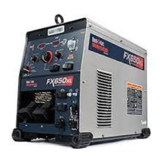
FX650XL
For use with machines having Code Numbers: 13018
OPERATOR'S MANUAL
Red-D-Arc Spec-Built Welding Equipment
This RED-D-ARC welder is built to RED-D-ARC Extreme Duty
design specifications by Lincoln Electric.
Safety Depends on You
This welder is designed and built with safety in mind.
However, your overall safety can be increased by proper installation
... and thoughtful operation on your part.
DO NOT INSTALL, OPERATE OR REPAIR THIS EQUIPMENT
WITHOUT READING THIS MANUAL AND THE SAFETY
PRECAUTIONS CONTAINED THROUGHOUT.
And, most importantly, think before you act and be careful.
1-800-245-3660
North America's Largest Fleet of Welding Equipment
Advertisement
Table of Contents

Related Manuals for Red-D-Arc Welderentals FX650XL


Summary of Contents for Red-D-Arc Welderentals FX650XL
- Page 1 IM10555 RED-D-ARC February 2021 FX650XL For use with machines having Code Numbers: 13018 OPERATOR’S MANUAL Red-D-Arc Spec-Built Welding Equipment This RED-D-ARC welder is built to RED-D-ARC Extreme Duty design specifications by Lincoln Electric. Safety Depends on You This welder is designed and built with safety in mind.
- Page 2 THANK YOU FOR SELECTING A QUALITY PRODUCT BY KEEP YOUR HEAD OUT OF THE FUMES. DON’T get too close to the arc. LINCOLN ELEC TRIC. Use corrective lenses if necessary to stay a reasonable distance away from the arc. READ and obey the Safety Data PLEASE EXAMINE CARTON AND EQUIPMENT FOR Sheet (SDS) and the warning label DAMAGE IMMEDIATELY...
- Page 3 SAFETY SECTION A: with hot engine parts and igniting. Do not spill fuel when lling tank. If fuel is spilled, wipe it up and do not start engine until WARNINGS fumes have been eliminated. 1.d. Keep all equipment safety guards, covers and devices in position and in good repair.
- Page 4 SAFETY ELECTRIC SHOCK ARC RAYS CAN BURN. CAN KILL. 3.a. The electrode and work (or ground) circuits are 4.a. Use a shield with the proper filter and cover plates to protect your electrically “hot” when the welder is on. Do eyes from sparks and the rays of the arc when welding or not touch these “hot”...
- Page 5 SAFETY WELDING AND CUTTING CYLINDER MAY EXPLODE IF SPARKS CAN CAUSE DAMAGED. FIRE OR EXPLOSION. 7.a. Use only compressed gas cylinders containing the correct shielding gas for the process used 6.a. Remove fire hazards from the welding area. If and properly operating regulators designed for this is not possible, cover them to prevent the welding sparks the gas and pressure used.
-
Page 6: Table Of Contents
Cable Connections........................A-5 Recommended Electrode and Work Cable for Arc Welding............A-6 Output Cable Guidelines.......................A-6 Control Cable Connections, Paralleling..................A-7 Connection Diagrams FX650XL to Wire Feeders and Tractor.........A-8 thru A-12 Operation......................Section B Safety Precautions ........................B-1 Graphic Symbols........................B-1, B-2 Product Description ........................ - Page 7 FX650XL INSTALLATION TECHNICAL SPECIFICATIONS - FX650XL POWER SOURCE-INPUT VOLTAGE AND CURRENT Model Duty Cycle Input Voltage ± 10% Input Amperes Power Factor @ Idle Power Effective Rated Output 60% rating 61 / 50 / 40 230 MAX.( Fan On) K3437-2...
- Page 8 FX650XL INSTALLATION WELDING PROCESS OUTPUT RANGE (AMPERES) OCV (U OCV (U PROCESS GMAW (CV) 40-815 GTAW (CC) 10-815 SMAW (CC) 15-815 40-815 FCAW-G (CV) FCAW-S (CV) 40-815 SAW (CV) 40-815 PHYSICAL DIMENSIONS MODEL HEIGHT WIDTH DEPTH WEIGHT K3437-2 165lbs (74.8kg)* 29.33 in (745 mm)
-
Page 9: Installation
FX650XL INSTALLATION INSTALLATION WARNING LIFTING The FX650XL has 2 lifting eyelets and 2 handles that can be used to lift the machine. Both handles or both eyelets should be used ELECTRIC SHOCK can kill. when lifting the FX650XL. • Only qualified personnel should When using a crane or overhead device to lift using the handles, a lifting strap should be connected to both handles. -
Page 10: High Temperature Operation
Only a qualified electrician should connect the input leads to Section. If the Auxiliary lead (indicated as ‘A’) is placed in the the FX650XL. connections should be made in accordance wrong position and power is applied to the machine, the machine... -
Page 11: Cable Connections
FX650XL INSTALLATION CAbLE CONNECTIONS See FIGURE A.2 for locating 5, 12 and 14 pin connectors on the front of the FX650XL. FIGURE A.2 12-PIN ACCESSORY CONNECTIVITY Function Wiring A ArcLink CAN B ArcLink CAN C Remote potentiometer, common 12-pin remote... -
Page 12: Output Cable Guidelines
Connect the electrode and work cables between the appropriate practical, and be sure all connections are clean and tight. output studs of the FX650XL per the following guidelines: Note: Excessive heat in the weld circuit indicates undersized • Most welding applications run with the electrode being cables and/or bad connections. -
Page 13: Control Cable Connections, Paralleling
Genuine Lincoln control cables should be used at all times (except control cables. where noted otherwise). Lincoln cables are specifically designed for the communication and power needs of the FX650XL. Most are designed to be connected end to end for ease of extension. PARALLELING... - Page 14 FX650XL INSTALLATION CONNECTING LF-72 AND LF-74 TO THE FX650XL WIRE FEEDER 14-PIN CONTROL CABLE K1797-XX LF-72 ELECTRODE LF-74 FX650XL WORK CONTROL SETTING WELD MODE CV, CV-INNERSHIELD WELD TERMINALS LOCAL REMOTE/LOCAL (REMOTE IF K2329-1 INSTALLED) VOLTMETER POLARITY PROCESS DEPENDENT...
- Page 15 FX650XL INSTALLATION CONNECTING LN-10 AND DH-10 TO THE FX650XL WIRE FEEDER 14-PIN CONTROL CABLE K1501-XX LN-10 DH-10 FX650XL ELECTRODE WORK CONTROL SETTING WELD MODE CV, CV-INNERSHIELD WELD TERMINALS REMOTE/LOCAL REMOTE VOLTMETER POLARITY PROCESS DEPENDENT LN-10,DH-10 CONTROL SWITCH SETUP Setting the DIP Switches...
- Page 16 FX650XL INSTALLATION CONNECTING LN-25 PRO, LN-25 PIPE, ACTIV8 TO THE FX650XL WIRE FEEDER LN-25 PRO LN-25 PIPE FX650XL ELECTRODE ACTIV8 WORK CLIP WORK CONTROL SETTING WELD MODE CV, CV-INNERSHIELD WELD TERMINALS REMOTE/LOCAL LOCAL PROCESS DEPENDENT VOLTMETER POLARITY CONNECTING LN-25 PRO DUAL POWER TO THE FX650XL...
- Page 17 ELECTRODE WORK CONTROL SETTING CV, CV-INNERSHIELD WELD MODE WELD TERMINALS REMOTE/LOCAL LOCAL VOLTMETER POLARITY PROCESS DEPENDENT CONNECTING LN-8 AND LN-9 TO THE FX650XL WIRE FEEDER 14-PIN CONTROL CABLE K1820-XX LN-8 LN-9 ELECTRODE FX650XL WORK CONTROL SETTING WELD MODE CV, CV-INNERSHIELD...
- Page 18 FX650XL INSTALLATION CONNECTING NA-3, NA-5 TO THE FX650XL WIRE FEEDER 14-PIN CONTROL CABLE K1820-XX NA-3 NA-5 FX650XL ELECTRODE WORK FOR NA-3 WIRE FEEDER ONLY: - MOVE JUMPER LEAD ON VARIABLE VOLTAGE BOARD TO "H" PIN. FOR NA-5 WIRE FEEDER ONLY: - MOVE "BLUE"...
-
Page 19: Operation
FX650XL OPERATION OPERATION SAFETY PRECAUTIONS Read this entire section of operating instructions before operating the machine. WARNING ELECTRIC SHOCK can kill. • Unless using cold feed feature, when feeding with gun trigger, the electrode and drive mechanism are always electrically energized and could remain energized several seconds after the welding ceases. -
Page 20: Graphic Symbols
FX650XL OPERATION GRAPHIC SYmbOLS THAT APPEAR ON THIS mACHINE OR IN THIS mANUAL REDUCED OPEN INPUT POWER CIRCUIT VOLTAGE OPEN CIRCUIT VOLTAGE INPUT VOLTAGE OUTPUT VOLTAGE HIGH TEMPERATURE INPUT CURRENT CIRCUIT BREAKER OUTPUT CURRENT PROTECTIVE WIRE FEEDER GROUND WARNING or CAUTION POSITIVE OUTPUT Read &... -
Page 21: Product Description
OPERATION PRODUCT DESCRIPTION RECOmmENDED PROCESSES The FX650XL is a multi-process CC/CV DC inverter and is rated for The FX650XL is designed for CC-SMAW, CC-GTAW (lift tig), CV- 650 amps, 44 volts at a 100% duty cycle. The GMAW, CV-FCAW-S, CV-FCAW-G and CV-SAW welding processes. - Page 22 18. Local/Remote Selector Toggle Switch: Sets the control of the output to local (output control knob) or remote through the six available weld modes for the FX650XL – CC- (K857-2 hand amptrol, K870-2 foot amptrol or 14-pin wire SMAW; CC-GTAW; CV; Multi-Weld™ / CV-Innershield; CV- feeder) SAW;...
-
Page 23: Case Back Controls
FX650XL OPERATION CASE bACk CONTROLS (See Figure B.2) 1. Input Power Cord Access Hole. 2. Access Panel – Allows access for connecting input power and configuring the machine. 3. Input Power Reconnect – Configures the machine for the input supply voltage. -
Page 24: Internal Controls
NA-3 or NA-5 controllers, or with an LT-7. The Turn switch #1 to the 'ON' Position (See Figure B.6). internal load resistance of the FX650XL will now increase when its output is disabled, allowing for the sensing circuitry on the wire 4. -
Page 25: Power-Up Sequence
ArcLink feeder. displays preset current value (either 2 amps or +/- 3% The FX650XL is also capable of gouging. Gouging can be done in (e.g. 3 amps on 100), whichever is greater). either the SMAW mode or the CV and CV-Innershield modes. - Page 26 OPERATION Control - Local/Remote Toggle Switch bASIC mODES OF OPERATION • Set the switch to “local” to control output at the FX650XL via the Output Control dial. SMAW • Set the switch to “remote” to control output via a remote...
- Page 27 Output Control welding voltage when the machine is in the idle state. After Dial on the front of the FX650XL. Set this switch to “Remote” welding, the meter holds the actual voltage value for 5 seconds.
- Page 28 Output Control (open circuit voltage) and ready to weld. This selection is Dial on the front of the FX650XL. Set this switch to “Remote” used for across the arc wire feeders. when an external potentiometer/control is connected.
- Page 29 ArcLink wire When using a CrossLinc™ enabled power source such as the feeders. All of the FX650XL user interface controls are disabled in FX650XL and a CrossLinc™ enabled wire feeder such as the LN-...
-
Page 30: Accessories
FX650XL ACCESSORIES OPTIONS / ACCESSORIES TIG Options General Options Pro-Torch™ TIG Torches – PTA-9, PTA- K2149-1 Work Lead Package. 17, PTA-26 – 2 piece power cord. Foot Amptrol - Provides 25 ft. (7.6 m) of K1842-10 10ft. Weld Power Cable (Lug to Lug). -
Page 31: Maintenance
FX650XL MAINTENANCE MAINTENANCE PERIODIC mAINTENANCE WARNING Safety Precautions Thermal Protection Thermostats protect the machine from excessive operating temperatures. Excessive temperatures may be caused by a lack of ELECTRIC SHOCK can kill. cooling air or operating the machine beyond the duty cycle and output rating. -
Page 32: Voltage Calibration
FX650XL MAINTENANCE VOLTAGE CALIbRATION TO RESTORE FACTORY CURRENT CALIbRATION 1. Connect a resistive load bank to the machine configured for 1. Connect the resistive load bank and test voltmeter to the 300A/20V (750A/50V equivalent). welding output terminals. 2. Connect a certified calibrated voltmeter to the output circuit. -
Page 33: How To Use Troubleshooting Guide
FX650XL TROUBLESHOOTING TROUBLESHOOTING How to Use troUblesHooting gUide WARNING Service and Repair should only be performed by Lincoln Electric Factory Trained Personnel. Unauthorized repairs performed on this equipment may result in danger to the technician and machine operator and will invalidate your factory warranty. - Page 34 FX650XL TROUBLESHOOTING PROBLEMS POSSIBLE RECOMMENDED Observe all Safety Guidelines detailed throughout this manual (SYMPTOMS) CAUSE COURSE OF ACTION BASIC MACHINE PROBLEMS Major physical or electrical damage is 1. Contact your local authorized Lincoln evident when the sheet metal covers are Electric Field Service facility for technical removed.
- Page 35 In addition, there are status lights on the control pc board and the board are dual-color LED’s. Normal operation for each is steady switch pc board that contain error sequences. green. FX650XL FAULT CODES Error Description Possible Cause Corrective Action...
- Page 36 FX650XL DIAGRAMS FRONT OF MACHINE...
- Page 37 FX650XL DIAGRAMS...
- Page 38 Index of Sub Assemblies - 12599 PART NUMBER DESCRIPTION P-1147-A INDEX OF SUB ASSEMBLIES P-1147-C CASE FRONT ASSEMBLY P-1147-D DIVIDER PANEL ASSEMBLY P-1147-E BASE ASSEMBLY P-1147-F CASE BACK ASSEMBLY P-1147-G COVERS ASSEMBLY FX650XL - 12599...
- Page 39 WARNING Do not touch electrically live parts or Keep flammable materials away. Wear eye, ear and body protection. electrode with skin or wet clothing. Insulate yourself from work and AVISO DE ground. Spanish PRECAuCION No toque las partes o los electrodos Mantenga el material combustible Protéjase los ojos, los oídos y el bajo carga con la piel o ropa moja-...
- Page 40 WARNING Keep your head out of fumes. Turn power off before servicing. Do not operate with panel open or Use ventilation or exhaust to guards off. remove fumes from breathing zone. AVISO DE Spanish PRECAuCION Los humos fuera de la zona de res- Desconectar el cable de ali- No operar con panel abierto o piración.
- Page 41 CUSTOMER ASSISTANCE POLICY The business of The Lincoln Electric Company is manufacturing and selling high quality welding equipment, consumables, and cutting equipment. Our challenge is to meet the needs of our customers and to exceed their expectations. On occasion, purchasers may ask Lincoln Electric for advice or information about their use of our products.
Need help?
Do you have a question about the FX650XL and is the answer not in the manual?
Questions and answers