
Related Manuals for Red-D-Arc Welderentals Auto-Line EXTREME 360 MAP


Summary of Contents for Red-D-Arc Welderentals Auto-Line EXTREME 360 MAP
- Page 1 OM-237881Y 2017−07 Processes Multiprocess Welding Description Arc Welding Power Source EXTREME 360 MAP ™ Auto-Line File: MULTIPROCESS...
-
Page 3: Table Of Contents
TABLE OF CONTENTS SECTION 1 − SAFETY PRECAUTIONS - READ BEFORE USING ....... . . 1-1. - Page 4 TABLE OF CONTENTS SECTION 8 − GMAW/GMAW-P/FCAW OPERATION ..........8-1.
-
Page 5: Section 1 − Safety Precautions - Read Before Using
SECTION 1 − SAFETY PRECAUTIONS - READ BEFORE USING som 2015−09 Protect yourself and others from injury — read, follow, and save these important safety precautions and operating instructions. 1-1. Symbol Usage DANGER! − Indicates a hazardous situation which, if Indicates special instructions. - Page 6 D Remove stick electrode from holder or cut off welding wire at FUMES AND GASES can be hazardous. contact tip when not in use. D Wear body protection made from durable, flame−resistant material Welding produces fumes and gases. Breathing (leather, heavy cotton, wool). Body protection includes oil-free these fumes and gases can be hazardous to your clothing such as leather gloves, heavy shirt, cuffless trousers, high health.
-
Page 7: Additional Symbols For Installation, Operation, And Maintenance
1-3. Additional Symbols For Installation, Operation, And Maintenance FIRE OR EXPLOSION hazard. MOVING PARTS can injure. D Do not install or place unit on, over, or near D Keep away from moving parts such as fans. combustible surfaces. D Keep all doors, panels, covers, and guards D Do not install unit near flammables. -
Page 8: California Proposition 65 Warnings
1-4. California Proposition 65 Warnings Welding or cutting equipment produces fumes or gases This product contains chemicals, including lead, known to which contain chemicals known to the State of California to the state of California to cause cancer, birth defects, or other cause birth defects and, in some cases, cancer. -
Page 9: Section 2 − Consignes De Sécurité − Lire Avant Utilisation
SECTION 2 − CONSIGNES DE SÉCURITÉ − LIRE AVANT UTILISATION fre_som_2015−09 Pour écarter les risques de blessure pour vous−même et pour autrui — lire, appliquer et ranger en lieu sûr ces consignes relatives aux précautions de sécurité et au mode opératoire. 2-1. - Page 10 chauffement ou un incendie. Avant de commencer le soudage, vérifier LES PIÈCES CHAUDES peuvent et s’assurer que l’endroit ne présente pas de danger. provoquer des brûlures. D Déplacer toutes les substances inflammables à une distance de D Ne pas toucher à mains nues les parties chaudes. 10,7 m de l’arc de soudage.
-
Page 11: Dangers Supplémentaires En Relation Avec L'installation, Le Fonctionnement Et La Maintenance
D Placer les bouteilles debout en les fixant dans un support station- déroule du soudage à l’arc, du soudage par points, du gougeage, de la découpe plasma ou une opération de chauffage par naire ou dans un porte-bouteilles pour les empêcher de tomber ou induction. -
Page 12: Proposition Californienne 65 Avertissements
D N’utiliser que les pièces de rechange recommandées par le LE SOUDAGE À L’ARC risque de constructeur. provoquer des interférences. D Effectuer l’installation, l’entretien et toute intervention selon les manuels d’utilisateurs, les normes nationales, provinciales et de D L’énergie électromagnétique risque l’industrie, ainsi que les codes municipaux. -
Page 13: Section 3 − Definitions
A complete Parts List is available at www.MillerWelds.com SECTION 3 − DEFINITIONS 3-1. Manufacturer Safety Symbols And Definitions Some symbols are found only on CE products. Warning! Watch Out! There are possible hazards as shown by the symbols. Safe1 2012−05 When power is applied failed parts can explode or cause other parts to explode. - Page 14 Welding sparks can cause fires. Have a fire extinguisher nearby, and have a watchperson ready to use it. Safe14 2012−05 Do not weld on drums or any closed containers. Safe16 2017−04 Do not remove or paint over (cover) the label. Safe20 2017−04 Flying pieces of parts can cause injury.
-
Page 15: Miscellaneous Symbols And Definitions
A complete Parts List is available at www.MillerWelds.com 3-2. Miscellaneous Symbols And Definitions Shielded Metal Remote Input Current Arc (SMAW) Elec- trode Holder Gas Metal Arc Volts Percent Welding (GMAW) Gas Output Scratch Start TIG Increase Positive Gas Metal Arc Rated Welding Welding (GMAW) Current... -
Page 16: Section 4 − Specifications
A complete Parts List is available at www.MillerWelds.com SECTION 4 − SPECIFICATIONS 4-1. Features And Benefits Auto-Linet Power Management Technology is circuitry that automatically adapts the power source to the primary voltage being applied (see Sections 5-8 and 5-9). LVCt Line Voltage Compensation is circuitry that keeps the power source output constant regardless of input power fluctuation. Wind Tunnel Technologyt circulates air over components that require cooling, not over electronic circuitry, which reduces contaminants and im- proves reliability in harsh welding environments. -
Page 17: Dimensions And Weight
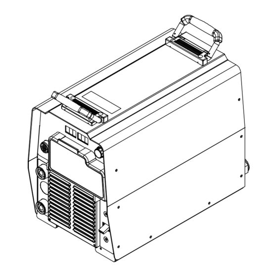
A complete Parts List is available at www.MillerWelds.com 4-5. Dimensions And Weight Hole Layout Dimensions 24 in. (610 mm) 11-3/4 in. (298 mm) 17 in. 1-11/16 in. (42 mm) (432 mm) 15-3/4 in. (400 mm) 19-3/32 in. (485 mm) 8-11/16 in. (221 mm) 12-1/2 in. -
Page 18: Duty Cycle And Overheating
A complete Parts List is available at www.MillerWelds.com 4-7. Duty Cycle And Overheating Duty Cycle is percentage of 10 min- utes that unit can weld at rated load without overheating. If unit overheats, output stops, a Help message is displayed and cooling fan runs. -
Page 19: Section 5 − Installation
A complete Parts List is available at www.MillerWelds.com SECTION 5 − INSTALLATION 5-1. Selecting A Location Movement Do not move or operate unit where it could tip. Location And Airflow Special installation may be required where gasoline or volatile liquids are present − see NEC Article 511 or CEC Section 20. -
Page 20: Selecting Cable Sizes
A complete Parts List is available at www.MillerWelds.com 5-2. Selecting Cable Sizes* NOTICE − The Total Cable Length in Weld Circuit (see table below) is the combined length of both weld cables. For example, if the power source is 100 ft (30 m) from the workpiece, the total cable length in the weld circuit is 200 ft (2 cables x 100 ft). Use the 200 ft (60 m) column to determine cable size. -
Page 21: Remote 14 Receptacle Information
A complete Parts List is available at www.MillerWelds.com 5-4. Remote 14 Receptacle Information Socket* Socket Information 24 volts AC. Protected by supplementary protect- 24 VOLTS AC or CB2. Contact closure to A completes 24 volts AC contactor control circuit. C L N Output to remote control;... -
Page 22: Optional Gas Valve Operation And Shielding Gas Connection
A complete Parts List is available at www.MillerWelds.com 5-6. Optional Gas Valve Operation And Shielding Gas Connection Obtain gas cylinder and chain to running gear, wall, or other station- ary support so cylinder cannot fall and break off valve. Cylinder Regulator/Flowmeter Install so face is vertical. -
Page 23: Electrical Service Guide
A complete Parts List is available at www.MillerWelds.com 5-7. Electrical Service Guide Elec Serv 2017−01 NOTICE − INCORRECT INPUT POWER can damage this welding power source. Phase to ground voltage shall not exceed +10% of rated input voltage. NOTICE − Actual input voltage should not be 10% less than minimum and/or 10% more than maximum input voltages listed in table. If actual input voltage is outside this range, output may not be be available. -
Page 24: Connecting 1-Phase Input Power
A complete Parts List is available at www.MillerWelds.com 5-8. Connecting 1-Phase Input Power =GND/PE Earth Ground Tools Needed: input1 2012−05 − Ref. 803766-C / 276319-B OM-237881 Page 20... - Page 25 A complete Parts List is available at www.MillerWelds.com 5-8. Connecting 1-Phase Input Power (Continued) nected to any input power between 208 and Disconnect Device (switch shown in the Installation must meet all National and 575 VAC without removing cover to relink the OFF position) Local Codes −...
-
Page 26: Connecting 3-Phase Input Power
A complete Parts List is available at www.MillerWelds.com 5-9. Connecting 3-Phase Input Power = GND/PE Earth Ground Tools Needed: Input2 2012−05 − Ref. 803766-C / Ref. 276319-B OM-237881 Page 22... - Page 27 A complete Parts List is available at www.MillerWelds.com 5-9. Connecting 3-Phase Input Power (Continued) voltage available at site. This unit can be con- Input Conductors (L1, L2 And L3) Installation must meet all National and nected to any input power between 208 and Local Codes −...
-
Page 28: Section 6 − General Operation
A complete Parts List is available at www.MillerWelds.com SECTION 6 − GENERAL OPERATION 6-1. Front Panel 804 772-B / 226 611-A 12 Remote PC Interface Weld process operation sections de- The meters display the actual weld output 13 Setup Button scribe functionality of the identified items. -
Page 29: Mode Switch Settings
A complete Parts List is available at www.MillerWelds.com 6-2. Mode Switch Settings Switch Position Process Output Control Panel Adjust Remote Adjust Scratch Start TIG GTAW Electrode Hot Amps % Panel Amps* Lift-Arc TIG GTAW Electrode Hot Amps % Panel Amps* GTAW Remote 14 Amps... -
Page 30: Configuration Option Menu
A complete Parts List is available at www.MillerWelds.com 6-3. Configuration Option Menu 226 611-A Mode Switch Setup Right Displays. SET−UP will be displayed momentarily. Remote 14 Receptacle The Configuration Option Menu provides a Configuration options are displayed in the Left Left Display means to customize some machine features Display. - Page 31 A complete Parts List is available at www.MillerWelds.com Configuration Option Menu (Continued) Pulsed MIG Adjustment ARC.L PULS This option allows adjusting the Pulsed MIG process in units of Arc Length (PULS ARC.L) or preset voltage (PULS VOLT). Wire Feed Speed And Wire Diameter Units WFS IPM: WFS is displayed in inches per minute Diameter is displayed in inches...
-
Page 32: Section 7 − Gtaw Operation
A complete Parts List is available at www.MillerWelds.com SECTION 7 − GTAW OPERATION 7-1. Typical Connection For GTAW Process Turn off power before mak- ing connections. Foot Control Gas Out Connection (Optional) Positive (+) Weld Output Terminal Remote 14 Receptacle Connect desired remote control to Remote 14 receptacle if required. -
Page 33: Scratch Start Tig Welding Mode - Gtaw Process
A complete Parts List is available at www.MillerWelds.com 7-2. Scratch Start TIG Welding Mode - GTAW Process 7 2. 0 226 611-A Setup Operation Weld terminals are energized at all times in Scratch Start TIG welding The Adjust Control is used to set desired For typical system connections refer to mode. -
Page 34: Lift-Arc Tig Welding Mode - Gtaw Process
A complete Parts List is available at www.MillerWelds.com 7-3. Lift-Arc TIG Welding Mode - GTAW Process 1 3. 5 226 611-A 1 − 2 “Touch” Seconds Do NOT Strike Like A Match! Setup Operation Weld terminals are energized at all times in Lift Arc TIG welding mode. -
Page 35: Tig Welding Mode - Gtaw Process
A complete Parts List is available at www.MillerWelds.com 7-4. TIG Welding Mode - GTAW Process 226 611-A Setup Operation Weld terminals energized through the remote control in TIG For typical system connections refer to The Adjust Control is used to set desired welding mode. -
Page 36: Section 8 − Gmaw/Gmaw-P/Fcaw Operation
A complete Parts List is available at www.MillerWelds.com SECTION 8 − GMAW/GMAW-P/FCAW OPERATION 8-1. Typical Connection For Remote Control Feeder GMAW/GMAW-P/FCAW Process 804938-B Workpiece Use of shielding gas is dependant on Wire Turn off power before making Type. connections. Remote 14-Receptacle The connection diagram illustrates Wire Feeder DCEP (reverse polarity) suitable for all... - Page 37 A complete Parts List is available at www.MillerWelds.com Notes OM-237881 Page 33...
-
Page 38: Mig Welding Mode - Gmaw/Fcaw Process
A complete Parts List is available at www.MillerWelds.com 8-2. MIG Welding Mode - GMAW/FCAW Process 226 611-A Press the Setup Button to confirm the Weld terminals energized The preset voltage can be adjusted re- selection. The unit will acknowledge a through the remote control in MIG motely at the wire feeder if the feeder change of wire and gas information by dis-... -
Page 39: Mig - Wire And Gas Selection Table
A complete Parts List is available at www.MillerWelds.com 8-3. MIG - Wire and Gas Selection Table WIRE TYPES** GAS TYPES DEFAULT INDUCTANCE .035 (0.9) STL ARGN CO2 (ARGON / CARBON DIOXIDE) .045 (1.2) STL ARGN OXY (ARGON / OXYGEN) .052 (1.4) STL Steel .035 (0.9) STL CO2 (CARBON DIOXIDE) -
Page 40: Pulsed Mig Welding Mode - Gmaw-P Process
A complete Parts List is available at www.MillerWelds.com 8-4. Pulsed MIG Welding Mode - GMAW-P Process 25.0 226 611-A Pulsed MIG − Wire and Gas Selection Arc Length - Pulsed MIG Manual Control Weld terminals energized Table for available wires and gases (see Section 6-3) through the remote control in (see Section 8-5). -
Page 41: Pulsed Mig - Wire And Gas Selection Table
A complete Parts List is available at www.MillerWelds.com 8-5. Pulsed MIG - Wire and Gas Selection Table WIRE TYPES* GAS TYPES ARGN CO2 (ARGON / CARBON DIOXIDE) .035 (0.9) STL Steel 80 ARGN CO2 (ARGON / CARBON DIOXIDE) .045 (1.2) STL ARGN OXY (ARGON / OXYGEN) .035 (0.9) STL Steel 100S... -
Page 42: Remote Process Select
A complete Parts List is available at www.MillerWelds.com 8-6. Remote Process Select This power source can be used with wire feeders that support Remote Process Se- lect. This feature allows the operator to switch the active welding process between MIG and Pulsed MIG at the wire feeder. To determine if the welding system is Remote Process Select capable, connect the wire feeder to the power source and review the... -
Page 43: Typical Connection For Voltage-Sensing Feeder Gmaw/Gmaw-P/Fcaw Process
A complete Parts List is available at www.MillerWelds.com 8-7. Typical Connection For Voltage-Sensing Feeder GMAW/GMAW-P/FCAW Process Turn off power before mak- ing connections. Positive (+) Weld Output Terminal Negative (−) Weld Output Terminal Ground Cable to Workpiece Workpiece Voltage Sensing Clamp Gun Trigger Receptacle Wire Feeder Gas Hose... -
Page 44: V-Sense Feeder Welding Mode - Gmaw/Fcaw Process
A complete Parts List is available at www.MillerWelds.com 8-8. V-Sense Feeder Welding Mode - GMAW/FCAW Process 226 611-A Operation Rotate Adjust Control to select desired gas. Weld terminals are energized at all times in V-Sense Feeder welding While the Volts Indicator is lit under the Left Press the Setup Button again to confirm the mode. -
Page 45: V-Sense Feeder Welding Mode - Gmaw-P Process
A complete Parts List is available at www.MillerWelds.com 8-9. V-Sense Feeder Welding Mode - GMAW-P Process R200 226 611-A ment of Arc Control, Wire Type, Gas Type Higher settings narrow the arc cone, re- Weld terminals are energized at all and Arc Length. -
Page 46: Section 9 − Smaw/Cac-A Operation
A complete Parts List is available at www.MillerWelds.com SECTION 9 − SMAW/CAC-A OPERATION 9-1. Typical Connection For SMAW And CAC-A Process Turn off power before mak- ing connections. Electrode Holder (Carbon Arc) For CAC-A process connect car- bon arc cutting torch to to positive weld output terminal. -
Page 47: Cc Welding Mode - Smaw/Cac-A Process
A complete Parts List is available at www.MillerWelds.com 9-2. CC Welding Mode - SMAW/CAC-A Process 226 611-A Press the Setup Button repeatedly until the Weld terminals energized If the remote control has an amperage Arc Control light goes out to return to ad- through the remote control in CC adjustment, the adjustment will func- justment of preset amperage. -
Page 48: Stick Welding Mode - Smaw/Cac-A Process
A complete Parts List is available at www.MillerWelds.com 9-3. Stick Welding Mode - SMAW/CAC-A Process 7 2. 0 226 611-A Right Display, the Adjust Control is used to Press the Setup Button repeatedly until the Weld terminals are energized at all set desired preset amperage. -
Page 49: Optional Low Open Circuit Voltage (Ocv) Welding Modes
A complete Parts List is available at www.MillerWelds.com 9-4. Optional Low Open Circuit Voltage (OCV) Welding Modes Low OCV Operation The unit can be optionally configured for low open circuit voltage (OCV) operation in Stick and Scratch Start TIG modes. When the unit is config- ured for low OCV operation only a low sensing voltage (approximately 15 VDC) is present between the electrode and the workpiece prior to the electrode touching the workpiece. -
Page 50: Section 10 − Maintenance & Troubleshooting
A complete Parts List is available at www.MillerWelds.com SECTION 10 − MAINTENANCE & TROUBLESHOOTING 10-1. Routine Maintenance Disconnect power Maintain more often during before maintaining. severe conditions. n = Check Z = Change ~ = Clean l = Replace Replace Damaged Replace Cracked Torch Body... -
Page 51: Help Displays
A complete Parts List is available at www.MillerWelds.com 10-3. Help Displays All directions are in reference to the front of the unit. All circuitry referred to is lo- cated inside the unit. Help 1 Display HELP Indicates a malfunction in the primary power circuit. -
Page 52: Troubleshooting
A complete Parts List is available at www.MillerWelds.com 10-4. Troubleshooting Trouble Remedy No weld output; unit completely inop- Place line disconnect switch in On position (see Sections 5-8 and 5-9). erative. Check and replace line fuse(s), if necessary, or reset circuit breaker (see Sections 5-8 and 5-9). Check for proper input power connections (see Sections 5-8 and 5-9). - Page 53 A complete Parts List is available at www.MillerWelds.com Notes OM-237881 Page 49...
-
Page 54: Section 11 − Electrical Diagram
SECTION 11 − ELECTRICAL DIAGRAM Figure 11-1. Circuit Diagram OM-237881 Page 50... - Page 55 271 735-B OM-237881 Page 51...
- Page 56 Notes...
- Page 57 Notes Start Your Professional Over 80,000 trained 400 Trade Square East, Troy, Ohio 45373 Welding Career Now! since 1930! 1-800-332-9448 www.welding.org...
- Page 58 Notes...
-
Page 59: Warranty
Warranty Effective January 1, 2017 (Equipment with a serial number preface of MH or newer) This limited warranty supersedes all previous Miller warranties and is exclusive with no other guarantees or warranties expressed or implied. LIMITED WARRANTY − Subject to the terms and conditions 6 Months —... - Page 60 Owner’s Record Please complete and retain with your personal records. Model Name Serial/Style Number Purchase Date (Date which equipment was delivered to original customer.) Distributor Address City State Contact the Delivering Carrier for: File a claim for loss or damage during shipment.
Need help?
Do you have a question about the Auto-Line EXTREME 360 MAP and is the answer not in the manual?
Questions and answers