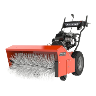
Ariens Power Brush 28 Service Manual
Hide thumbs
Also See for Power Brush 28:
- Service manual (42 pages) ,
- Manual (30 pages) ,
- Parts manual (20 pages)

Related Manuals for Ariens Power Brush 28


Summary of Contents for Ariens Power Brush 28
- Page 1 Service Manual Power Brush 28 Model 921056 – Power Brush 28 (SN 000101 +) ENGLISH 05175130C • 6/20...
-
Page 2: Table Of Contents
TABLE OF CONTENTS PRACTICES & LAWS..... . 2 Install Gearbox ....... . 27 U-JOINT ASSEMBLY REPLACEMENT . - Page 3 Be aware of your mechanical aptitude when applying information in this manual for service and / or repairs. If you are not comfortable or capable of completing service and / or repairs to the machine, take the machine to an authorized Ariens service dealer. © 2020 • AriensCo • Brillion, WI 54110...
-
Page 4: Practices & Laws
Emission controls and 2. Warning components can only be adjusted by an Ariens dealer or an WARNING: Indicates a POTENTIALLY authorized engine manufacturer's service center. Contact HAZARDOUS SITUATION! If not avoided, your Ariens Retailer concerning emission controls and COULD RESULT in death or serious injury. -
Page 5: Safety Decals
SAFETY DECALS Stop engine, remove key, and read manual The safety decals on your machine are visual reminders of before making any repairs or adjustments. the important safety information in this manual. All messages on your unit must be fully understood and carefully followed. -
Page 6: Safety Rules
Handle fuel with care; it is highly flammable. 4. DANGER! • Use an approved fuel container. • NEVER add fuel to a running engine or hot engine. DANGER! • Fill fuel tank outdoors with extreme care. NEVER fill fuel tank indoors. •... - Page 7 After striking a foreign object, stop the engine, remove the NEVER allow anyone to operate this unit when their wire from the spark plug, disconnect the cord on electric alertness or coordination is impaired. motors, thoroughly inspect the unit for any damage, and NEVER touch a hot engine or muffler.
- Page 8 Personal Protection Fuel DO NOT operate the equipment without wearing Remove fuel before separating brush attachment from adequate clothing. Avoid loose fitting clothing that can get frame. Ensure unit is secure and will not tip during caught in moving parts. Wear footwear that will improve maintenance.
-
Page 9: Draining Fuel System
DRAINING FUEL SYSTEM SEPARATE BRUSH FROM FRAME Move unit to an open, well-ventilated area with no IMPORTANT: Save all hardware for reinstallation. flames or sparks. Move unit to a flat, level surface. Remove fuel tank cap and siphon fuel into a clean Turn engine key to off position, remove key and close gasoline container. - Page 10 Remove hardware retaining belt finger and remove Disconnect brush lock cable from J-clamp on engine belt finger. See Figure 3. mount. See Figure 5. Figure 5 Figure 3 Remove machine screw and lock washer retaining WARNING: AVOID INJURY. Attachment sheave brush lock trigger and disconnect trigger assemble edges are sharp.
-
Page 11: Install Brush To Frame
INSTALL BRUSH TO FRAME WARNING: ALWAYS support tractor / frame Reinstall brush attachment mount bracket onto mount when loosening hardware retaining it to brush rod. See Figure 9. attachment. See Figure 7. 10. Position support under handlebar so tractor / frame will not tip when disconnected from brush attachment. -
Page 12: Bottom Cover Removal
BOTTOM COVER REMOVAL See Figure 10. Check belt finger clearance: Remove Bottom Cover • Engage attachment clutch lever and traction clutch IMPORTANT: Save all hardware for reinstallation. lever and ensure that belt finger located opposite belt Turn engine key to off position, remove key and close idler is less than 3.2 mm (1/8”) from belt, but not fuel valve. -
Page 13: Install Bottom Cover
Install Bottom Cover ATTACHMENT DRIVE BELT REPLACEMENT Reinstall bottom cover and secure with six hex bolts. Return unit to operating position and support Remove Attachment Drive Belt handlebar. Ensure that unit is secure and will not tip. IMPORTANT: Save all hardware for reinstallation. Turn engine key to off position, remove key and close CAUTION: AVOID ENGINE DAMAGE. -
Page 14: Traction Drive Belt Replacement
TRACTION DRIVE BELT See Figure 14. Remove spring clip from swing gate pivot rod. REPLACEMENT Remove hardware retaining support bushing and Remove Traction Drive Belt swing gate spacer. Remove bushing and spacer. IMPORTANT: Save all hardware for reinstallation. Turn engine key to off position, remove key and close fuel valve. -
Page 15: Install Traction Drive Belt
Install Traction Drive Belt WARNING: AVOID INJURY. Wear thick gloves; traction drive pulley and traction sheave edges WARNING: AVOID INJURY. Wear thick gloves; are sharp. traction drive pulley and traction sheave edges are sharp. See Figure 15. Remove swing gate from stop hole and support See Figure 16. -
Page 16: Attachment Brake Replacement
ATTACHMENT BRAKE REPLACEMENT See Figure 17. NOTICE: Ensure that support bushings are flush with Remove Attachment Brake frame. IMPORTANT: Save all hardware for reinstallation. Reinstall swing gate spacer, align with right support Turn engine key to off position, remove key and close bushing and secure with two tapping screws. - Page 17 See Figure 19 and Figure 20. Check that gap between attachment brake arm roller and tractor frame is 1.3 cm – 2.2 cm (1/2” – 7/8”). See Engage and disengage attachment clutch to verify Figure 21. brake roller on attachment idler does not interfere with brake pad.
-
Page 18: Friction Disc Replacement
FRICTION DISC REPLACEMENT Remove hairpin from adjustment pivot pin and remove pin from shift arm. See Figure 23. Remove Friction Disc IMPORTANT: Save all hardware for reinstallation. WARNING: AVOID INJURY. Before rotating unit forward, drain fuel from tank and fuel system. See Draining Fuel System on page 7. -
Page 19: Install Friction Disc
Install Friction Disc Remove hardware retaining left bearing flange to frame and remove flange and bearing. See Figure 25. See Figure 27. Align friction disc assembly with shift fork roller bearing and hex shaft. Reinstall hex shaft through friction disc assembly. Figure 25 See Figure 26. -
Page 20: Swing Gate Replacement
SWING GATE REPLACEMENT See Figure 29. Reinstall spring clips into hex shaft. Remove Swing Gate IMPORTANT: Save all hardware for reinstallation. Turn engine key to off position, remove key and close fuel valve. Wait for all moving parts to stop and for hot parts to cool. -
Page 21: Install Swing Gate
Install Swing Gate See Figure 31. Remove spring clip from swing gate pivot rod. See Figure 33. Remove hardware retaining support bushing and Reinstall traction drive belt around traction drive pulley swing gate spacer. Remove bushing and spacer. and traction drive sheave. Reinstall swing gate into support bushing and stop hole in frame. -
Page 22: Hex Shaft Bearing Replacement
HEX SHAFT BEARING REPLACEMENT See Figure 34. Reinstall support bushing onto pivot rod. Remove Bearing Reinstall swing gate spacer, align with support IMPORTANT: Save all hardware for reinstallation. bushing and secure with tapping screws removed in Turn engine key to off position, remove key and close step 7. -
Page 23: Brush Replacement
BRUSH REPLACEMENT See Figure 37. Remove snap rings from brush shaft ends. Remove Brush Remove hardware retaining reduction idler mount and IMPORTANT: Save all hardware for reinstallation. remove mount. Turn engine key to off position, remove key and close IMPORTANT: Be aware of flat special washers on fuel valve. - Page 24 See Figure 38. See Figure 39. Remove hardware retaining drive sprocket. 10. Remove Woodruff key from brush shaft. Remove drive sprocket, reduction idler sprocket and 11. Remove hardware retaining bearing flanges and driven sprocket. remove flanges from each side of attachment frame. 12.
-
Page 25: Install Brush
Install Brush See Figure 43. Reinstall two spacers onto left brush shaft end. IMPORTANT: Reinstall interior bearing flanges, if removed. See Figure 41. Reinstall one spacer onto right brush shaft end. Reinstall shaft bearings into attachment frame. Figure 41 See Figure 42. Install brush and align with attachment frame holes. - Page 26 See Figure 45. See Figure 46. 11. Apply a thin layer of anti-seize compound to 14. Reinstall Woodruff key into brush shaft. transmission shaft. 15. Reinstall chain onto driven sprocket and align with 12. Align reduction sprocket and drive sprocket with chain. reduction sprocket.
-
Page 27: Gearbox Replacement
GEARBOX REPLACEMENT See Figure 47. 17. Reinstall snap ring onto brush shaft end. Remove Gearbox 18. Reinstall reduction idler mount through hole in frame IMPORTANT: Save all hardware for reinstallation. and secure with four tapping screws. Turn engine key to off position, remove key and close 19. - Page 28 See Figure 49. Remove brush frame from mounting assembly. See Figure 50. Remove hardware retaining coupling hub to transmission shaft and remove hub from gearbox output shaft. IMPORTANT: Use of penetrating oil or heat may be necessary to remove hub from gearbox output shaft. Remove hardware retaining brush frame mount to mounting plates.
-
Page 29: Install Gearbox
Install Gearbox Align coupling hub with Woodruff key and reinstall hub over output shaft. See Figure 54. See Figure 52. Apply a thin layer of anti-seize compound to gearbox input shaft. Position gearbox inside brush frame mount and insert input shaft into U-joint assembly. Figure 54 Figure 52 Secure coupling hub to transmission shaft with original... -
Page 30: U-Joint Assembly Replacement
U-JOINT ASSEMBLY REPLACEMENT Remove hardware retaining attachment drive pulley to U-joint shaft and remove pulley and spacer. See Remove U-Joint Assembly Figure 56. IMPORTANT: Save all hardware for reinstallation. Turn engine key to off position, remove key and close fuel valve. Wait for all moving parts to stop and for hot parts to cool. -
Page 31: Replace U-Joint Assembly Bearings
REPLACE U-JOINT ASSEMBLY CASTER WHEEL REPLACEMENT BEARINGS IMPORTANT: Save all hardware for reinstallation. NOTICE: Only replace one caster wheel at a time. Remove U-Joint Bearings Turn engine key to off position, remove key and close IMPORTANT: Save all hardware for reinstallation. fuel valve. -
Page 32: Install Caster Wheel
ENGINE REPLACEMENT Remove spacer from wheel. See Figure 61. Remove Engine IMPORTANT: Save all hardware for reinstallation. Turn engine key to off position, remove key and close fuel valve. Wait for all moving parts to stop and for hot parts to cool. -
Page 33: Install Engine
Install Engine See Figure 63. 12. Remove hardware retaining attachment drive sheave Install key into crankshaft keyway. and remove sheave. Reinstall traction drive sheave and attachment drive 13. Remove traction drive sheave. sheave onto crankshaft and secure with original locking washer and hex bolt. 14. -
Page 34: Differential Gear Replacement
DIFFERENTIAL GEAR REPLACEMENT See Figure 65. Slide long axle out from differential gear far enough to Remove Differential Gear gain access to differential gear. It is not necessary to IMPORTANT: Save all hardware for reinstallation. fully remove long axle. WARNING: AVOID INJURY. Before rotating unit forward, drain fuel from tank and fuel system. -
Page 35: Install Differential Gear
Install Differential Gear Reinstall bottom cover and secure with six hex bolts. Position axles keys and reinstall wheels. Secure Align differential gear with pinion gear and reinstall wheels with snap clips. onto axle. See Figure 67. Rotate tractor to operating position, support handlebar and reinstall brush attachment. -
Page 36: Pinion Gear Bushing Replacement
PINION GEAR BUSHING See Figure 70. IMPORTANT: Sleeve bushing between pinion gear and REPLACEMENT frame will fall when pinion shaft is removed. Remove Bushings Remove pinion shaft from pinion gear. IMPORTANT: Save all hardware for reinstallation. WARNING: AVOID INJURY. Before rotating unit forward, drain fuel from tank and fuel system. -
Page 37: Install Flange Bushings
Install Flange Bushings DUAL-HANDLE INTERLOCK CAM REPLACEMENT Install flange bushings into pinion gear. See Figure 72. Remove Interlock Cams Reinstall pinion gear into chain and align with IMPORTANT: Save all hardware for reinstallation. differential gear. Turn engine key to off position, remove key and close Reposition sleeve bushing between pinion gear and fuel valve. -
Page 38: Install Interlock Cams
Install Interlock Cams IMPORTANT: Interlock cams will fall from camshafts in next step. IMPORTANT: Ensure that nylon bushings are seated in Remove hardware retaining camshafts and remove interlock bracket. See Figure 76. camshafts from interlock bracket. See Figure 75. Figure 76 Reinstall right camshaft through interlock bracket and secure to clutch lever with original tapping screw. -
Page 39: Traction Drive Clutch Cable
Operator’s Manual for test procedure. IMPORTANT: If dual-handle interlock continues to Figure 79 malfunction, see your Ariens dealer. WARNING: AVOID INJURY. Before rotating unit forward, drain fuel from tank and fuel system. See Draining Fuel System on page 7. Ensure that unit is secure and will not tip. -
Page 40: Install Traction Drive Clutch Cable
Install Traction Drive Clutch Cable Remove hairpin and washer from upper traction drive lever pin. Remove spring and cable. See Figure 80. Secure lower traction drive clutch cable to swing gate with one flat steel washer and hairpin. See Figure 79. Feed cable through hole in unit rear. -
Page 41: Axle Bushing Replacement
AXLE BUSHING REPLACEMENT Install Left Axle Bushing Install bushing onto axle and secure with three tapping Remove Left Axle Bushing screws from inside frame. IMPORTANT: Save all hardware for reinstallation. Reinstall flat steel washer. Reinstall bottom cover and secure with six hex bolts. WARNING: AVOID INJURY. -
Page 42: Remove Right Axle Bushing
Remove Right Axle Bushing Remove e-clip from axle, slide long axle to right and remove differential from short axle. IMPORTANT: Save all hardware for reinstallation. See Figure 84. WARNING: AVOID INJURY. Before rotating unit 10. Remove E-ring from right axle end. forward, drain fuel from tank and fuel system. -
Page 43: Install Right Axle Bushing
Install Right Axle Bushing 13. Remove differential from short axle to gain access to tapping screws. See Figure 90. Install bushing onto short axle and secure with three tapping screws from inside frame. Reinstall flat steel washer and differential onto short axle. - Page 44 See Figure 89. Align pinion gear with chain and differential gear. Position one sleeve bushing between pinion gear and frame and reinstall pinion shaft. Figure 89 Position sleeve bushing against frame and reinstall spring clip into pinion shaft. See Figure 90. Figure 90 Secure bottom cover to frame with six hex bolts.
- Page 45 SERVICE RECORD DATE SERVICE COMPLETED NOTES EN – 43...
- Page 46 655 West Ryan Street Brillion, WI 54110 www.ariensco.com parts.ariens.com...
Need help?
Do you have a question about the Power Brush 28 and is the answer not in the manual?
Questions and answers