Advertisement
Quick Links
Advertisement

Related Manuals for MICROPOINT qLabs Vet


Summary of Contents for MICROPOINT qLabs Vet
- Page 1 All manuals and user guides at all-guides.com QV-3 Plus ® qLabs User’s Manual...
- Page 2 All manuals and user guides at all-guides.com Table of Contents 1. Introduction ..............5 1.1 Before You Start ...............5 1.2 Intended Use ..............5 1.3 Test Principle ..............5 1.4 Packaging ................5 2. Product Overview ............6 3. Operation Summary ............8 4. Before Testing ..............8 5.
- Page 3 All manuals and user guides at all-guides.com 7.5.2 Codeship Strip ............19 7.5.3 Refrence range ............. 21 7.5.4 PT units ..............22 7.5.5 APTT units ............22 7.6 System Parameter ............23 7.6.1 Date/Time ............. 23 7.6.2 Beeper ..............24 7.6.3 Screen Rotation ............ 24 7.6.4 Brightness Adjustment ..........
- Page 4 All manuals and user guides at all-guides.com 9.4 Input QC Information ............38 9.5 Install QC Liquid Codechip ..........39 9.6 Heating ................40 9.7 Add Sample ..............40 9.8 QC Test .................40 9.9 QC Test Results .............41 10. Results .................42 10.1 Results Channel ............42 10.2 Test Results ..............43 10.3 QC result ..............44 11.
- Page 5 All manuals and user guides at all-guides.com 1. Introduction 1.1 Before You Start ® Before using qLabs Vet, read the User's Manual as well as the package inserts for all relevant consumables carefully. 1.2 Intended Use ® ® The qLabs Vet system, which consists of qLabs Vet instrument ®...
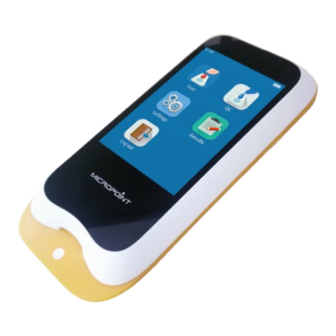
- Page 6 All manuals and user guides at all-guides.com 2. Product Overview Front View 1. Test Strip Guide 2. Touchscreen Back View 3. Footpad 4. Battery Cover with Label 5. Magnetic Charging Port...
- Page 7 All manuals and user guides at all-guides.com Left View Right View 6. Power Button 7.Codechip Strip slot Top View 8. Micro USB Data Port 9. DC 5V Power Supply Jack...
- Page 8 All manuals and user guides at all-guides.com 3. Operation Summary Operation Preparation Bluetooth Sample No. Reference APTT Units Language PT Units WIFI Switch Switch Codechip Range Setting Setting Setting Setting Setting Setting Meter Setup Transport Date/Time Beeper Backlight Screen Sleep Upload/Print Operator ID Mode...
- Page 9 5.1 Care of Your qLabs ® ● DO NOT spill any liquid on the qLabs Vet. In this case, immedi- ately contact the local distributor of Micropoint. ® ● The qLabs Vet is a delicate instrument and should be handled with care.
- Page 10 All manuals and user guides at all-guides.com netic radiation, as these may interfere with the proper operation of the instrument. 5.3 Patient health Status Current patient health status may cause inaccurate or unexpected test results. It is important to take certain health factors into consideration when interpreting the test results and deciding on a course of action for your patients.
- Page 11 All manuals and user guides at all-guides.com ● The user must use the matching 5V special charger provided by Micropoint to charge. ● Do not bring the meter close to a high-temperature heat source. ● Do not allow the meter to be hit or exert heavy pressure on the meter.
- Page 12 All manuals and user guides at all-guides.com 6. Power ON/OFF 6.1 Battery and Charging When turning on the meter for the first time after unpacking, please connect the adapter for power supply and turn off the transportation mode. You do not need to repeat this operation for subsequent reboot. Ensure the meter is fully charged before using for the first time.
- Page 13 All manuals and user guides at all-guides.com Once Operator ID is On, the Log out icon in Main screen will be enabled and displayed in brown (see figure 1-2). To switch between the operators, please return to the screen for inputting the operator ID by pressing the Log out icon, and then re-enter the operator ID.
- Page 14 All manuals and user guides at all-guides.com 6.4 Power OFF After a press of the Power button for 3 seconds, the system will deliver a message to select. Press " " to power off the instrument, or press " " to cancel the operation (see figure 1-4).
- Page 15 All manuals and user guides at all-guides.com 7. Setting 7.1 Enter setting screen Click the "Settings" icon from the main menu screen (Figure 1-2) to enter the Settings screen (Figure 2-1). 7.2 Language Click "Language" from the Settings screen (Figure 2-1) to enter the screen that prompts the user to select a language (Figure 2-2).
- Page 16 All manuals and user guides at all-guides.com Click “WIFI” from Settings menu (see Figure 2-1) to enter the WIFI menu (see Figure 2-3). When the WIF button is displayed in blue, it means WIFI is turned on; when the WIFI button is grayed out, it means WIFI is turned off.
- Page 17 All manuals and user guides at all-guides.com The loss of signal or access to bandwidth of one particular client may vary depending on one or more of the following situations: the type and number of other clients, the performance of the Access Point, the presence of electromagnetic disturbances, and other potential interfering factors, e.g., concrete walls.
- Page 18 All manuals and user guides at all-guides.com When Bluetooth is set to On and Discoverable Mode is closed, the meter automatically searches for the connectable base. Touch one of the bases in the search result list after completing the search, the screen then displays “connecting...”, and the meter displays "connected"...
- Page 19 All manuals and user guides at all-guides.com 7.5 Test Parameter Click "Test Parameter" from the Setting screen (Figure 2-1) to enter the screen (Figure 2-10) that prompts the user to set the parameters. 2-10 7.5.1 Sample NO. Click "Sample No." from the Test Parameter screen (Figure 2-10) to enter the screen (Figure 2-11) that prompts the user to set the sample...
- Page 20 All manuals and user guides at all-guides.com Click “Test Strip” from Codechip menu (see figure 2-12) to enter Test Strip menu (see figure 2-13). The Codechip information of the installed strip then displayed in this menu. A new strip Codechip can also be installed by inserting the strip Codechip into the Codechip slot (see the right figure on Section...
- Page 21 All manuals and user guides at all-guides.com In addition to being installed from Codechip menu, a Codechip can also be installed during the test. When testing with a test strip or control with a Codechip installed, the installation operation is no longer required during the test;...
- Page 22 All manuals and user guides at all-guides.com Click any value in the Reference Range table to automatically enter the menu which allow the user to modify the value, and the user can re-modify the upper and lower limits (see figure 2-16) within the given setting range.
- Page 23 All manuals and user guides at all-guides.com 7.6 System Parameter Click "System Parameter" from the Settings screen (Figure 2-1) to enter the screen (Figure 2-19) that prompts the user to set the system parameter.Click " " to return to the previous screen and click " "...
- Page 24 All manuals and user guides at all-guides.com 7.6.2 Beeper Click "Beeper" from the System Parameter screen (Figure 2-19) to enter the screen (Figure 2-21) that prompts the user to set the beeper. The beeper is turned off when the beeper button is grayed out.The beeper is turned on when the beeper button is blue, and the user can set different volume: high,...
- Page 25 All manuals and user guides at all-guides.com 7.6.4 Brightness Adjustment Click "Brightness" from the System Parameter screen (Figure 2-19) to enter the brightness adjustment screen (Figure 2-23). The adjustment range is between 1 and 10. Click " " to return to the previous screen and click "...
- Page 26 All manuals and user guides at all-guides.com 7.6.6 Print and Upload Click "Auto Print/Upload" from the System Parameter screen (Figure 2-19) to enter the print upload setting screen (Figure 2-25). The auto print/upload function is disabled when the button is grayed out.
- Page 27 All manuals and user guides at all-guides.com 7.7 About the Device Click "About the Device" from Settings screen (Figure 2-1) to enter the screen that displays the system information (Figure 2-27). The user can check the version and log information.Click " "...
- Page 28 All manuals and user guides at all-guides.com After touching "User Management" from the operator ID screen (Figure 2-28), the administrator can enter the screen and view the created user list (Figure 2-29). To create a new user account, please touch "...
- Page 29 If the administrator forgets the password, please contact the local distributor or relevant technicians of Micropoint. 2-31 The user can log in to any existing account from the Login screen. Enter the correct password and log into the screen to perform the relevant operation.
- Page 30 All manuals and user guides at all-guides.com 8. Sample Test 8.1 Choosing test type In the test type interface, choosing the test type, the available test types include: feline, canine and others. Click " " to return to the previous screen and click "...
- Page 31 All manuals and user guides at all-guides.com 8.3 Insert a Test Strip Save the sample No. and enter the strip insertion screen, then insert the test strip in the direction shown in Figure 3-3. Keep inserting the strip from the right direction until the sample well on it is align with the dot on the instrument.
- Page 32 All manuals and user guides at all-guides.com When Meter scans, the indicator will be automatically lights up first. The white area in the rectangular light field is the sensing area. When scanning, the scan port should be aligned with the barcode, and the position, distance and angle between the barcode and scan port should be adjusted according to the light field.
- Page 33 All manuals and user guides at all-guides.com When the input Codechip number of the test strip has expired, the system will deliver a warning message indicating that the Codechip has expired. 8.6 Heating After the test strip is inserted and its Codechip is installed, the instrument will enter the heating state, and the screen will display the heating...
- Page 34 All manuals and user guides at all-guides.com 8.8 Collecting a sample After the heating is complete, collect whole blood samples and run test. Refer to the test strip insert for detailed sample collecting procedures. NOTE: ● To avoid mechanical hemolysis of the blood sample, nonheparinized syringe with 21 gauge needle or larger is highly recommended.
- Page 35 All manuals and user guides at all-guides.com 8.10 Test Results Please check the strip insert for the results and explanation. The system will display the test results after the test is completed (Figure 3-9). The test results can be printed or uploaded, provided that the instrument is properly connected to the printer or server.
- Page 36 Failure of Quality Control test will result in the instrument displaying an error code. Please repeat the test utilizing a new test strip. ● Liquid QC Test Micropoint Biotechnologies Co., Ltd. has optional liquid controls for ® ® ®...
- Page 37 All manuals and user guides at all-guides.com 9.2 Input Test Strip Information After the test strip is inserted, please enter the test strip information screen (Figure 4-2), and input the Codechip number of the test strip, the Codechip number can be inputted through manually input and click "...
- Page 38 All manuals and user guides at all-guides.com When the input Codechip number of the test strip does not match the Codechip information, the system will provide a warning message indicating that the Codechip information does not match. When the input Codechip number of the test strip has expired, the system will provide a warning message indicating that the...
- Page 39 All manuals and user guides at all-guides.com 9.5 Install QC Liquid Codechip The screen will display the specific Codechip information of the QC liquid (Figure 4-5) after inputting the Codechip information of the QC liquid. When the input Codechip number of QC liquid does not match the Codechip information, the system will provide a warning message...
- Page 40 All manuals and user guides at all-guides.com 9.6 Heating After the test strip is inserted and Codechip is installed, the instrument will enter the heating state, and the screen will display the heating progress (Figure 4-6). 9.7 Add Sample The system will count down and prompt the user to add sample (Figure 4-7) upon the completion of heating, and the sample must be...
- Page 41 All manuals and user guides at all-guides.com 9.9 QC Test Results The system will display the QC test results after the test is completed (Figure 4-9). The test results can be printed or uploaded, provided that the instrument is properly connected to the printer or server.
- Page 42 All manuals and user guides at all-guides.com 10. Results When the storage amount of the sample result reaches 80% of the total amount of the meter, the user will be prompted to upload data. If the user does not upload the data, the sample results will automatically overwrite the oldest records after the total amount exceeds the limit.
- Page 43 All manuals and user guides at all-guides.com 10.2 Test Results Click "Test Result" from the result screen (Figure 5-1) to enter the test result query screen (Figure 5-3). If there are multiple test results, please scroll through the display for all results.
- Page 44 All manuals and user guides at all-guides.com 10.3 QC result Click "QC Test" Result from the result screen (Figure 5-1) to enter the QC test result query screen (Figure 5-5). If there are multiple QC test results, please scroll through the display to list all results.
- Page 45 All manuals and user guides at all-guides.com 11. Maintenance 11.1 Care and Cleaning of Your Screen ® Follow these steps for cleaning the qLabs Vet: 11.1.1 Cleaning Frequency 1. Clean the meter after every patient and when there are signs of visible soil and/or organic material prior to disinfecting.
- Page 46 All manuals and user guides at all-guides.com 3. Recommended cleaning cloths are listed in table 1 4. The button area on the face of the meter Table 1. Recommended Cleaning cloths. Name Disinfectant Size PDI SaniCloth Quaternary/low-alcohol formula 8" x 14", or 6" x ®...
- Page 47 When stored for more than 3 months, it is recommended to turn on the transportation mode after charging every 3 months to avoid battery discharge and capacity attenuation. 11.3 Servicing No user serviceable components. All service and adjustment must be performed by Micropoint Biotechnologies Co., Ltd.
- Page 48 All manuals and user guides at all-guides.com 12. Troubleshooting When you receive an error code, please retest. If you receive a second error code, then contact your local distributor and test the patient with a laboratory method. Do not interpret an error code as a patient result in any case.
- Page 49 All manuals and user guides at all-guides.com Error Code Description Corrective Actions Please ensure that the test strip and control are within the expiry period, E006 External QC failed. and enter the correct test strip Codechip number and control Codechip number.
- Page 50 All manuals and user guides at all-guides.com Error Code Description Corrective Actions Please turn off the meter and reboot it. If the E015 Bluetooth error. problem recurs, please contact the relevant technical staff. Please retest with a new test strip. If the problem recurs, please contact E016 FIB calculation error.
- Page 51 All manuals and user guides at all-guides.com Error Code Description Corrective Actions Please retest with a new test strip. If the problem recurs, please contact E021 PT calculation error. your local dealer and use the laboratory method to perform the test. Please retest with a new test strip.
- Page 52 All manuals and user guides at all-guides.com Error Code Description Corrective Actions Make sure that the meter is properly communicating with the base and that E032 Print error. printing paper at the base is installed correctly and that there is sufficient paper.
- Page 53 All manuals and user guides at all-guides.com 13. Symbols SYMBOLS EXPLANATION SYMBOLS EXPLANATION Consult Instructions Expiry Date For Use Caution. Read Fragile Carefully Keep Dry Biological Risk Separate Collection Do Not Reuse Temperature Manufacturer Limitation Catalogue Number Serial Number Laser Radiation Risk Lot Number CE Marking...
- Page 54 All manuals and user guides at all-guides.com 14. Operating Condition and Product Specifications 14.1 Operating Condition Temperature 10ºC ~ 35ºC / 50ºF ~ 95ºF Humidity 10% ~ 90% (No condensation) Altitude 4300 m (14,000 feet) 14.2 Product Specifications Processor 32-Bits V2 ARM Cortex-M4 Display 320×480 LCD Touch screen...
- Page 55 Micropoint Biotechnologies Co., Ltd.’s only liability and purchaser’s only remedy under this warranty is that during the warranty period Micropoint Biotechnologies Co., Ltd. shall replace or repair, at no charge, any Meter component with defects in material or workmanship. MICROPOINT BIOTECHNOLOGIES CO., LTD. MAKES NO OTHER...
- Page 56 IN CONNECTION WITH THE METER, REGARDLESS OF THE LEGAL OR EQUITABLE BASIS OF ANY CLAIM, IS LIMITED TO THE PURCHASE PRICE OF THE METER. IN NO EVENT WILL MICROPOINT BIOTECHNOLOGIES CO., LTD. BE LIABLE FOR ANY INCIDENTAL, INDIRECT, SPECIAL, CONSEQUENTIAL, OR PUNITIVE LOSS OR DAMAGES IN ANY WAY RELATED TO THE METER, OR ANY THIRD PARTY.
- Page 57 518101 Shenzhen, China” Tel: +86 755 21600849 Fax: +86 755 86673903 Email: customerservice@micropointbio.com www.micropointbio.com ©2020 Micropoint Biotechnologies Co., Ltd. All rights reserved. Printed in China. qLabs and Micropoint are registered trademarks of Micropoint Biotechnologies Co., Ltd. ® ® P/N 630-00293 Rev.A1 2020-12...
Need help?
Do you have a question about the qLabs Vet and is the answer not in the manual?
Questions and answers