Advertisement
Quick Links
Advertisement

Related Manuals for Nibe Contura C 26K High


Summary of Contents for Nibe Contura C 26K High
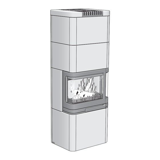
- Page 1 Installation instructions C 26K High www.contura.eu...
- Page 2 Emissions of hazardous substances Approved Nominal output 6 kW Efficiency Flue gas temperature in connector at nominal 280°C output The undersigned is responsible for the manufacture and conformity with the declared performance. Niklas Gunnarsson, Business area manager NIBE STOVES Markaryd, 1st July 2013...
- Page 3 CONTENTS A warm welcome to Contura. A warm welcome to the Contura family. We hope you will get a great deal of pleasure from your new stove. As a new owner of a Contura stove, you have secured a product with timeless design and long service life. Contura also has a combustion process that is both environmentally friendly and efficient, for the best heat production.
- Page 4 0,14% Distance to cumbustible wall (mm): Behind 150 Beside 450 Corner 150 Follow the user’s instructions and use only recomended fuel NIBE AB Box 134 SE-285 23 MARKARYD SWEDEN HANDÖL Type: 50-series Production no. 7090300236 NIBE AB SE-85 21 Markaryd Sweden...
- Page 5 SUPPLY AIR/ACCESSORY Supply of combustion air When a stove is installed in a room, the air supply demand to the room increases. Air can be provided indirectly via a vent in the outer wall or via a duct from the outside that is connected to the connector on the underneath of the stove.
- Page 6 CHIMNEY Connection to chimney • The stove meets the requirements for connecting to chimneys • A flue with sharp bends and horizontal routing reduces the dimensioned for flue gas temperatures of 350°C. draught in the chimney. The maximum horizontal flue is 1 m, on the condition that the vertical flue length is at least 5 m.
- Page 7 INSTALLATION DISTANCES Installation distances C26K High A = height from floor to chimney connection upwards Place the stove on the Combustible roof B = height from floor to c/c chimney connection rear hearth plate and check C = distance from back to c/c chimney connection upwards that the installation D = distance from back to chimney connection rear distances are not less...
- Page 8 ASSEMBLY Installation of C26 K High The stove needs to be placed on a level and horizontal surface, so the courses do not end up uneven and crooked. Otherwise, this can result in abnormally large gaps and uneven lines. During assembly, check that all tiles stand horizontally and that all parts in a course are of a uniform height.
- Page 9 ASSEMBLY Place the profile edge to edge with the tile's side.
- Page 10 ASSEMBLY Wait to tighten this screw until the next tile is in place.
- Page 11 ASSEMBLY When installing the two upper courses: Wait to tighten the screws in the tile until all parts are in place and all adjustments have been made. Prevent the side panels from dipping forward by hooking the hooks in the rear profile and tightening the screws until they engage For the oven option, go to page 96...
- Page 12 ASSEMBLY Not with the heat reservoir option...
- Page 13 ASSEMBLY The front plates are moved up slightly by hooking the hooks in the rear profile and tightening the screws. Tighten the screws until the upper plates align with the upper edge. Tighten all screws in the tiling. For the heat reservoir option, go to page 100 Final inspection of the installation It is extremely important that the installation is inspected by an authorised chimney sweep before the stove is used.
- Page 14 ASSEMBLY Final installation and joining Adjustment screws for placement in the guide plate to support the top plates. Adjust them, so they are at the same height as the top of the side plates. Open and fold out any deformed edges in the pipe opening to facilitate installation.
- Page 15 ASSEMBLY Check that the damper Ensure that joints are clean and dry before applying the can be opened and sealant. closed without problem. Work the sealant in with a lightly dampened sponge in diagonal movements. After the sealant has dried the tiles can be wiped clean.
- Page 16 ASSEMBLY Installation of oven (option) Use the corner profiles that are Push the aluminium hoses into the rear corners, so they are packed together with the oven. not in the way of the oven. Tighten all screws in the tiling. The front plates are moved up slightly by hooking the hooks in the rear profile and tightening the screws.
- Page 17 ASSEMBLY Move the insert's sleeve to the oven's top or back, depending on whether the chimney is to be connected to the top or back.
- Page 18 ASSEMBLY Check that the sealing rope between the insert and the oven does not move out of position. Use the enclosed screw and washers (2) to screw the oven into the insert. First, carry out any straightening and height adjustment that may be needed, using the four adjustment screws.
- Page 19 ASSEMBLY The slab that is placed in the oven's bottom can be taken out and washed. If necessary, fine sandpaper can be used to freshen up the surface. The slab can be used on both sides. When using the stone slab, bear in mind that the stone becomes significantly hotter than the air in the oven.
- Page 20 ASSEMBLY Installation of heat reservoir(option) Go to page 94 for final installation and joining NIBE AB · Box 134 · SE-285 23 Markaryd · Sweden www.contura.eu Contura reserves the right to change colours, materials, dimensions and models at any time without special notice.
Need help?
Do you have a question about the Contura C 26K High and is the answer not in the manual?
Questions and answers