
Related Manuals for KINSHOFER KM 506 HD

Summary of Contents for KINSHOFER KM 506 HD
- Page 1 Betriebsanleitung für hydraulischen Schnellwechsler Operating Instructions for Hydraulic Quick Change System Mode d’emploi pour système d'accrochage rapide hydraulique KM 506 HD Smart Flow January 2022 [en]...
- Page 2 KInshofer KM 506 HD 21.01.2022...
- Page 3 The type plate on the attachment must be clearly legible at all times. The type plate pictured below or similar is fastened onto the attachment: La plaque signalétique de l'outil doit toujours être bien lisible. La plaque signalétique comme représentée au-dessous ou semblable est fixée sur l'outil: 21.01.2022 KM 506 HD...
- Page 4 KInshofer Technische Daten / Technical Data / Données Techniques KM506 HD Drehmotor / Rotator KM 506 05 KM 506 01 HD KM 506 02 HD KM 506 04 HD KM 506 03 HD KM 506 HD 21.01.2022...
- Page 5 / lbs kNm (mt) / ft.lbs. KM04S68-30US 4500 / 9900 4500 / 3320 KM04S68-30IT 4500 / 9900 4500 / 3320 KM 506 HD 45 / 100 120 (12) / 88500 KM06S68-35 6000 / 13200 8500 / 6270 KM06S68-40 6000 / 13200 4500 / 3320 Artikelnr.
-
Page 6: Table Of Contents
KInshofer Content Important notes ......................7 Safety instructions ............................ 7 Statutory safety and accident prevention ....................7 Transport, unloading and unpacking ......................8 Inspection upon delivery ........................... 8 Service link ............................... 8 Product information ..................... 9 Product overview ............................9 Proper intended use .......................... -
Page 7: Important Notes
KInshofer Important notes These operating instructions apply to the attachment described on the title page, which was developed and produced with the utmost dedication. Technical information, mounting and maintenance instructions are provided in this manual. Service manual and spare parts list A service manual is available upon request for carrying out repairs on premium line products. -
Page 8: Transport, Unloading And Unpacking
The completeness of the delivery with reference to delivery note. Use the original packaging for any return shipping. Otherwise, dispose of the packaging in accordance with the regional regulations. Service link Replacement parts • Technical support • Returns • Service link http://www.kinshofer.com/de/index.php/de/service 21.01.2022... -
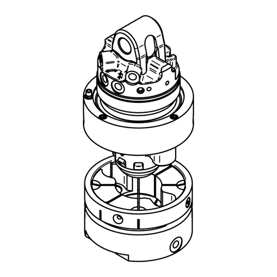
Page 9: Product Information
KInshofer Product information For example: Rotator Product overview KM 04S68-30US Quick change system KM 506 HD Attachment (shown here: KM 605 Clamshell bucket) Non-rotating hook with mechanical For example: lower part KM 506 03 HD Rotator Mechanical KM04S68-30US lower part... -
Page 10: Proper Intended Use
KInshofer Proper intended use The Quick Change System KM 506 HD is for exchanging attachments such as clamshell buckets and hooks from rotator KM04 or KM06, mounted on a crane. There is no need for manual handling when exchanging attachments. -
Page 11: Safety Sticker
KInshofer WARNING Danger of injury, possible property damage and loss of functional safety if the instructions are not observed. Use a carrier with operating weight as stated in chapter Technical data. Mount the attachment to the carrier using a cardanic suspension or a quick change adapter for cardanic suspension. -
Page 12: Safety Sticker For Indicator Pin: Green For „Locked
KInshofer 2.5.1 Safety sticker for indicator pin: green for „locked“. In correctly locked postion, the green indicator pin protruds approx. 5 mm. See Chater Operation. Installation and Initial operation Installation requirements on the crane On the crane, prepare the installation of the electro-hydraulic control system of the coupler. -
Page 13: Installation Of The Upper Part Of The Quick Coupler Onto The Rotator
KInshofer When operating with remote control, program the buttons on the remote control e.g., so that all 3 solenoid coils of the valve block are programmed separately on 3 buttons. This means different combinations are used for locking and unlocking. - Page 14 KInshofer 21.01.2022...
-
Page 15: Installation Of The Lower Part Of The Quick Coupler Onto The Attachment
KInshofer 3.1.2 Installation of the lower part of the quick coupler onto the attachment The parts 12 to 22 must be dismantled and then reassembled. See figure next page. Dismantling of parts 1. Remove the countersunk screws (15). 2. Remove cover plate (14), 2 protective plates (12), 4 washers (13). - Page 16 KInshofer 21.01.2022...
-
Page 17: Hydraulic Diagram With Valve Block
KInshofer 3.1.3 Hydraulic diagram with valve block "Engage quick coupler" function: Activation of valves 2 and 8, plus: "Close grab" By executing these functions, the hydraulic lines for the open / close grab function at the crane are depressurized. This facilitates engaging on the quick coupler. -
Page 18: Mounting Holes At Valve Block
KInshofer 3.1.4 Mounting holes at valve block 3.1.5 Connections at rotator Abbreviation Function Connection thread at rotator Open grab M18x1,5 Close grab M18x1,5 Rotate rotator M18x1,5 Disengage quick coupler M10x1 3.1.6 Pressure and oil flow Requirements of the carrier machine To operate the attachment correctly, set the operating pressure and oil flow at the truck crane as indicated at section Technical data of these operating instructions. -
Page 19: Operation
KInshofer Operation WARNING Installation, operation and maintenance of the attachment may only be carried out by authorized, trained and experienced personnel. 3.2.1 Exchanging attachments Prior to operation, ensure that the upper part of the quick coupler KM 506 01 HD is mounted on the rotator. The rotator is •... - Page 20 KInshofer Visual check of the lock indicator. Ensure the green indicator pin is visible. Correctly locked Incorrectly locked The green indicator pin is visible. All 4 safety catches are correctly locked. In At least 1 of the 4 safety catches is not locked position, the green indicator pin correctly locked.
-
Page 21: Non-Rotating Load Hook With Mechanical Lower Part Km 506 03 Hd
KInshofer 3.2.2 Non-rotating load hook with mechanical lower part KM 506 03 HD Procedure for connecting the non-rotating load hook: Open the hook adapter: Insert the KM506 upper part 1. Push the adapter halves back into the hook adapter onto by together 1. -
Page 22: Troubleshooting
KInshofer Troubleshooting Malfunction Cause Remedy The quick coupler does The crane is not completely Lower crane slightly to set down not disengage. relieved of the weight of the the attachment attachment. Hydraulic quick release couplings Make sure that the „pressure are under pressure. -
Page 23: Cleaning And Care
KInshofer NOTICE Risk to health and environment from oil spills. When disassembling, hydraulic oil in the hoses and pipes of the attachment and the carrier machine may spill out. To collect the oil, place a suitable collection pan beneath the hydraulic connections ... -
Page 24: Maintenance And Service
KInshofer Maintenance and service Maintenance To ensure safety and functionality and to prolong the life of the attachment, carry out daily inspections and maintenance as specified. Maintenance must be carried out in accordance with the maintenance check list. Maintenance work must be carried out by specially trained personnel. -
Page 25: Maintenance Check List
KInshofer Maintenance check list Maintenance intervals Daily Grease at grease nipples Check hydraulic connections for leaks and tighten if necessary. Every 50 operating Check locking sleeve for wear by visual inspection. Ensure the edges are not worn, edges hours... -
Page 26: Daily Inspection
KInshofer Daily inspection • Check the product for deformation, cracks and wear. • Check all hydraulic connections and hydraulic lines for leaks and externally visible damage. If necessary, replace all damaged parts in order to assure operational safety. • Apply grease to the grease nipple with a grease gun (see chapter on Technical information - overview of greasing points) until grease starts to emerge from between the bearings. -
Page 27: Replace Locking Sleeve
KInshofer Check if the release unit (1) is on • tight. • If the release unit is loose, tighten the set screws (4) 6.5.2 Replace locking sleeve Replace worn locking sleeve up to end of June 2021: Insert a long hexagonal wrench size 3 through the hole in the locking sleeve and turn out the set screw underneath. - Page 28 KInshofer Replace worn locking sleeve starting July 2021: - Starting approx. July 2021, the locking sleeves have an M4 female thread. - Use a nut or similar with M4 thread as a knock-out tool to remove the locking sleeve. - If the locking sleeve cannot be removed, heat the safety catch to approx. 150°C using a blowtorch or hot air blower to melt the thread glue.
-
Page 29: Tightening Torques For Bolted Connections
KInshofer 6.5.3 Tightening torques for bolted connections Tightening torques for cylinder and hexagon head cap screws and nuts Cylinder/hexagon-head cap screws and nuts Quality 10.9 12.9 10.9 12.9 class Thread Tightening torques in Nm Tightening torques in ft-lbs 10,5 12,5... - Page 30 KInshofer Tightening torques for retaining screws and nuts (friction coefficient 0.125) Locking screws and nuts (friction coefficient 0.125) Type Tensile locking screws and nuts Ribbed screws and nuts Quality class Class 80 Class 100 Class 100 Carrier Steel Cast iron...
- Page 31 KInshofer Tightening torques for hydraulic connection - DKJ (JIC) DKJs are Imperial nut runners with a sealing taper (27°). Tightening torque for DKJ hydraulic connection Nominal size Union nut thread Size ft-lbs F.F.F.T. ¼" 7/16-20 in 15-17 10.8-12.5 3/8" 9/16-18 in 27-30 19.6-22.0...
-
Page 32: Replacement Of The Hydraulic Components Every 6 Years
KInshofer Replacement of the hydraulic components every 6 years Regardless of the operating times, replace hydraulic hoses, hydraulic quick couplings and screwed connections on the attachment every 6 years. Commissioning after being shut down for one month or more Complete all maintenance work according to Maintenance inspection list. -
Page 33: Claims, Warranty, And Liability
KInshofer Claims, warranty, and liability Complaint In the event of a complaint, contact the contracting party or manufacturer. After agreement with the manufacturer, return damaged parts in their original packaging. Enclose a completed returns form with the return. Include the serial number of the attachment. See important information chapter. -
Page 34: Certificate Of Inspection
KInshofer Certificate of Inspection After each inspection, the manufacturer advises to replace the round sticker for date of next inspection. Stickers can be obtained from the manufacturer. Fill out for proof of inspection: Type of Attachment: Serial number: Year Date... -
Page 35: Ec-Declaration Of Conformity
Operation of work equipment Other country-specific health and safety regulations Authorised person to compile the technical documentation: Manager technical documentation, Kinshofer GmbH Kinshofer is ISO 9001 certified through DVS ZERT e.V., Düsseldorf, Germany Kinshofer GmbH Raiffeisenstraße 12 83607 Holzkirchen Germany The original signed declaration is included in the shipping documents. - Page 36 KInshofer 21.01.2022...
- Page 37 Via Savio, 29/31 47027 IT-70056 Sarsina FC Tel.: +39 0547 698020 kinshofer.com Fax: +39 0547 698021 Email: cangini@canginibenne.com www.canginibenne.com KINSHOFER is an ISO 9001 certified Company. DVS ZERT is a registred trademark of DVS ZERT e. V ., Düsseldorf. ®...
Need help?
Do you have a question about the KM 506 HD and is the answer not in the manual?
Questions and answers