Table of Contents
Advertisement
Quick Links
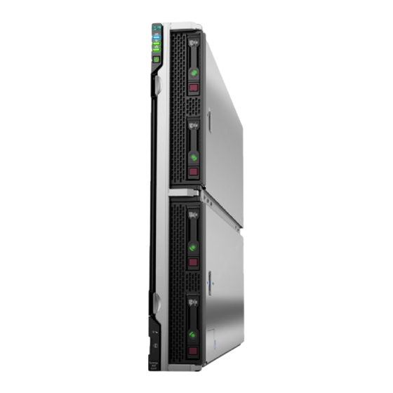
HPE Synergy 660 Gen10 Compute Module
Maintenance and Service Guide
Abstract
This document is for the person who installs, administers, and troubleshoots compute modules
and storage systems. Hewlett Packard Enterprise assumes you are qualified in the servicing of
computer equipment and trained in recognizing hazards in products with hazardous energy levels.
Part Number: 876829-006
Published: June 2019
Edition: 6
Advertisement
Table of Contents
Troubleshooting

Related Manuals for HPE Synergy 660 Gen10


Summary of Contents for HPE Synergy 660 Gen10
- Page 1 HPE Synergy 660 Gen10 Compute Module Maintenance and Service Guide Abstract This document is for the person who installs, administers, and troubleshoots compute modules and storage systems. Hewlett Packard Enterprise assumes you are qualified in the servicing of computer equipment and trained in recognizing hazards in products with hazardous energy levels.
- Page 2 © Copyright 2017, 2019 Hewlett Packard Enterprise Development LP Notices The information contained herein is subject to change without notice. The only warranties for Hewlett Packard Enterprise products and services are set forth in the express warranty statements accompanying such products and services.
-
Page 3: Table Of Contents
HPE 16GB NVDIMM spare part..................... 13 HPE Persistent Memory module spare parts................13 Compute module options........................13 Storage controller spare parts....................14 HPE Trusted Platform Module 2.0 spare part.................15 Mezzanine option spare parts....................15 Energy pack options....................... 15 Drive spare parts........................16 HPE Synergy Internal SATA board spare part................21 M.2 flash drive spare parts..................... - Page 4 HPE Synergy Glossary......................67 HPE Synergy troubleshooting resources...................67 Troubleshooting within HPE OneView..................67 HPE Synergy Troubleshooting Guide..................67 Error Message Guide for HPE ProLiant Gen10 servers and HPE Synergy......67 HPE OneView Help and HPE OneView API Reference............67 HPE Synergy QuickSpecs...................... 67...
- Page 5 DIMM slot locations........................ 80 DIMM label identification......................81 NVDIMM identification......................83 NVDIMM LED identification....................84 HPE Persistent Memory module label identification............... 85 Component and LED identification for HPE Synergy hardware............86 Cabling......................87 Cabling resources..........................87 Energy pack option cabling....................... 87 Standard drive backplane cabling..................... 87 P416ie-m Smart Array Controller cabling..................
-
Page 6: Illustrated Parts Catalog
Illustrated parts catalog Mechanical components Hewlett Packard Enterprise continually improves and changes product parts. See the Hewlett Packard Enterprise PartSurfer website for complete and current supported parts information. Item Description Access panel spare part DIMM baffle spare parts Compute module end cap spare part SFF drive blank spare part Front panel/drive cage assembly spare parts Drive backplane spare parts... -
Page 7: Access Panel Spare Part
Access panel spare part Customer self repair on page 23: mandatory Description Spare part number Access panel 873087-001 DIMM baffle spare parts Customer self repair on page 23: mandatory Description Spare part number DIMM baffles 873088-001 Compute module end cap spare part Customer self repair on page 23: mandatory Description Spare part number... -
Page 8: System Components
First generation Intel Xeon Scalable Processor spare parts Second generation Intel Xeon Scalable Processor spare parts (not shown) System board spare part HPE 16GB NVDIMM spare part (not shown) See Removal and replacement procedures for more information. System battery spare part... -
Page 9: Processor Heatsink Spare Parts
First Generation Intel Xeon Scalable Processor spare parts Customer self repair on page 23: no All Intel Xeon processors in this HPE ProLiant server must have the same cache size, speed, number of cores, and rated maximum power consumption. Illustrated parts catalog... - Page 10 Table 3: 51XX processors Description Spare part number Xeon-G 5115 10c 85W (GHz? Not found in 878082-001 partsurfer) Xeon-G 5118 12c 2.3-GHz 105W 875717-001 Xeon-G 5120 14c 2.2-GHz105W 875718-001 Xeon-G 5122 4c 3.6-GHz 105W 875719-001 Table 4: 61XX processors Description Spare part number Xeon-G 6126 12c 2.6-GHz 125W 875720-001...
-
Page 11: Second Generation Intel Xeon Scalable Processor Spare Parts
Second Generation Intel Xeon Scalable Processor spare parts Customer self repair on page 23: no All Intel Xeon processors in this HPE ProLiant server must have the same cache size, speed, number of cores, and rated maximum power consumption. Table 6: 32XX processors... - Page 12 Description Spare part number Xeon-G 5218N 16c 2.3-GHz 105W P12021-001 Xeon-G 5220 18c 2.2-GHz 125W P11613-001 Xeon-G 5220S 18c 2.6-GHz 125W P11627-001 Xeon-G 5222 4c 3.8-GHz 105W P11632-001 Table 9: 62XX processors Description Spare part number Xeon-G 6222V 20c 1.8-GHz 115W P12019-001 Xeon-G 6226 12c 2.7-GHz 125W P12008-001...
-
Page 13: System Board Spare Parts
Customer self repair on page 23: mandatory Description Spare part number NVDIMM 16GB 1Rx4 NN4-2666V-R 874540-001 HPE Persistent Memory module spare parts Customer self repair on page 23: mandatory Description Spare part number HPE Persistent Memory module, 128 GB 844071-001... -
Page 14: Storage Controller Spare Parts
Item Description Storage controller spare parts HPE Trusted Platform Module 2.0 spare part Energy pack option spare parts Mezzanine option spare parts (Mezz D card shown) Drive spare parts • SFF SAS HDD spare parts • SFF SATA HDD spare parts •... -
Page 15: Hpe Trusted Platform Module 2.0 Spare Part
HPE Trusted Platform Module 2.0 spare part Customer self repair on page 23: no Description Spare part number HPE Trusted Platform Module 2.0 Gen 10 kit, TAA 872159-001 Mezzanine option spare parts Customer self repair on page 23: optional Description... -
Page 16: Drive Spare Parts
Description Spare part number HPE Smart Storage Hybrid Capacitor, 260mm cable P07474-001 Drive spare parts SFF SAS HDD spare parts Customer self repair on page 23: mandatory Description Spare part number 600 GB SAS 15,000-rpm, SC 512e DS HDD 870797-001... - Page 17 Description Spare part number 1 TB SATA 7,200-rpm, SFF SC 512e DS HDD 765868-001 2 TB SATA 7,200-rpm, SFF SC 512e DS HDD 765869-001 1 TB SATA 7,200-rpm, SFF SC DS HDD 656108-001 SFF SAS SSD spare parts Customer self repair on page 23: mandatory Description Spare part number 400 GB 12G MU SC SSD...
- Page 18 Description Spare part number 1.6 TB MU DS SC SSD P06580-001 1.6 TB MU SC DS SSD P09924-001 1.6 TB WI DS SC SSD P06604-001 1.6 TB WI SC DS SSD P09949-001 1.92 TB 12G RI SC SSD 872433-001 1.92 TB MU SC VS DS SSD P10607-001 1.92TB RI DS SC SSD P06597-001...
- Page 19 Description Spare part number 240 GB SATA 6G RI SC DS SSD 868924-001 240 GB SATA RI DS SC SSD 875652-001 240 GB SATA RI SC DS SSD P05319-001 240 GB SATA RI SC DS SSD P08565-001 400 GB SATA 6G WI SC DS SSD 872512-001 480 GB SATA RI SC DS SSD P05320-001...
- Page 20 Description Spare part number 1.92 TB SATA MU SC DS SSD P09912-001 3.84 TB SATA MU DS SC SSD P02562-001 3.84 TB SATA 6G RI SC DS SSD 868932-001 3.84 TB SATA RI SC DS SSD P05315-001 3.84 TB SATA RI SC DS SSD P05323-001 3.84 TB SATA RI DS SC SSD P06574-001...
-
Page 21: Hpe Synergy Internal Sata Board Spare Part
SSD 340 GB 830453-001 USB and microSD option spare parts Customer self repair on page 23: mandatory Description Spare part number HPE Dual 8GB microSD EM USB device 799057-001 8-GB USB flash media key 743503-001 8-GB micro SDHC flash media card 738576-001... -
Page 22: Serial Label Pull Tab Spare Parts
Description Spare part number 960 GB SATA M.2 2280 RI DS 875856-001 960 GB SATA M.2 2280 MU DS 875852-001 Serial label pull tab spare parts Customer self repair on page 23: mandatory Description Spare part number Serial label pull tab 873074-001 Cable spare parts Customer self repair on page 23: mandatory... -
Page 23: Customer Self Repair
Customer self repair Hewlett Packard Enterprise products are designed with many Customer Self Repair (CSR) parts to minimize repair time and allow for greater flexibility in performing defective parts replacement. If during the diagnosis period Hewlett Packard Enterprise (or Hewlett Packard Enterprise service providers or service partners) identifies that the repair can be accomplished by the use of a CSR part, Hewlett Packard Enterprise will ship that part directly to you for replacement. - Page 24 Hewlett Packard Enterprise de remplacer ces pièces, l'intervention peut ou non vous être facturée, selon le type de garantie applicable à votre produit. REMARQUE: Certaines pièces Hewlett Packard Enterprise ne sont pas conçues pour permettre au client d'effectuer lui-même la réparation. Pour que la garantie puisse s'appliquer, Hewlett Packard Enterprise exige que le remplacement de la pièce soit effectué...
- Page 25 essere restituito con la documentazione associata nell'imballo di spedizione fornito. La mancata restituzione del componente può comportare la fatturazione del ricambio da parte di Hewlett Packard Enterprise. Nel caso di riparazione da parte del cliente, Hewlett Packard Enterprise sostiene tutte le spese di spedizione e resa e sceglie il corriere/vettore da utilizzare.
- Page 26 Parts-only Warranty Service (Garantieservice ausschließlich für Teile) Ihre Hewlett Packard Enterprise Garantie umfasst möglicherweise einen Parts-only Warranty Service (Garantieservice ausschließlich für Teile). Gemäß den Bestimmungen des Parts-only Warranty Service stellt Hewlett Packard Enterprise Ersatzteile kostenlos zur Verfügung. Für den Parts-only Warranty Service ist das CSR-Verfahren zwingend vorgegeben. Wenn Sie den Austausch dieser Teile von Hewlett Packard Enterprise vornehmen lassen, werden Ihnen die Anfahrt- und Arbeitskosten für diesen Service berechnet.
- Page 27 componentes, tendrá que hacerse cargo de los gastos de desplazamiento y de mano de obra de dicho servicio. Customer Self Repair Veel onderdelen in Hewlett Packard Enterprise producten zijn door de klant zelf te repareren, waardoor de reparatieduur tot een minimum beperkt kan blijven en de flexibiliteit in het vervangen van defecte onderdelen groter is.
- Page 28 Hewlett Packard Enterprise) concluir que o reparo pode ser efetuado pelo uso de uma peça CSR, a Hewlett Packard Enterprise enviará a peça diretamente ao cliente. Há duas categorias de peças CSR: • Obrigatória—Peças cujo reparo feito pelo cliente é obrigatório. Se desejar que a Hewlett Packard Enterprise substitua essas peças, serão cobradas as despesas de transporte e mão-de-obra do serviço.
- Page 29 Customer self repair...
- Page 30 Customer self repair...
- Page 31 Customer self repair...
-
Page 32: Removal And Replacement Procedures
Removal and replacement procedures Required tools You need T-15 and a T-30 Torx screwdrivers for performing procedures listed in this document. Safety considerations Before performing service procedures, review all the safety information. Preventing electrostatic discharge To prevent damaging the system, be aware of the precautions you must follow when setting up the system or handling parts. - Page 33 This symbol indicates the presence of hazardous energy circuits or electric shock hazards. Refer all servicing to qualified personnel. WARNING: To reduce the risk of injury from electric shock hazards, do not open this enclosure. Refer all maintenance, upgrades, and servicing to qualified personnel. This symbol indicates the presence of electric shock hazards.
-
Page 34: Compute Module Preparation
Select the Momentary press power off selection in HPE OneView. ◦ Select the Momentary press virtual power button selection in HPE iLO. • If a graceful shutdown fails to power down the compute module to standby mode when an application or OS stops responding, force a nongraceful shutdown of applications and the OS. -
Page 35: Removing The Compute Module
◦ Select the Press and hold power off selection in HPE OneView. ◦ Select the Press and hold virtual power button selection in HPE iLO. Removing the compute module Prerequisites CAUTION: Before proceeding, verify that the compute module is in standby mode by observing that the system power LED is amber, and verify that the UID LED is not flashing blue. - Page 36 Procedure 1. Verify that the device bay is configured for a half-height compute module. For more information, see the setup and installation guide for the frame on the Hewlett Packard Enterprise website. 2. Remove the compute module end cap. 3. Prepare the compute module for installation by opening the compute module handle 4.
-
Page 37: Removing And Replacing An Access Panel
Removing and replacing an access panel Procedure 1. Power down the compute module . 2. Remove the compute module. 3. Press the access panel release button. 4. Slide the access panel towards the rear of the compute module, and then lift to remove the panel. To replace the component, reverse the removal procedure. -
Page 38: Removing And Replacing A Drive
Removing and replacing a drive Procedure 1. Determine the status of the drive from the drive LED definitions. 2. Back up all data on the drive. 3. Remove the drive. To replace the drive, slide the drive into the bay until it is fully seated, and then close the latch handle to lock the drive in the bay. -
Page 39: Removing And Replacing A Compute Module End Cap
To replace the component, reverse the removal procedure. More information Powering down the compute module on page 34 Removing and replacing a compute module end cap Procedure 1. Power down the compute module. 2. Remove the compute module. 3. Place the compute module on a flat, level work surface. 4. -
Page 40: Removing And Replacing A Heatsink Blank
To replace the component, reverse the removal procedure. Removing and replacing a heatsink blank Procedure 1. Power down the compute module . 2. Remove the compute module. 3. Place the compute module on a flat, level work surface. 4. Remove the access panel. 5. -
Page 41: Removing And Replacing Dimm Baffles
To replace the component, reverse the removal procedure. Removing and replacing DIMM baffles Procedure 1. Power down the compute module . 2. Remove the compute module. 3. Place the compute module on a flat, level work surface. 4. Remove the access panel. 5. -
Page 42: Dimm-Processor Compatibility
DIMM baffle. See "DIMM slot locations" to identify DIMMs installed in the compute module. 6. Remove the DIMM. To replace the component, reverse the removal procedure. Use HPE UEFI System Utilities to configure the memory mode. Removal and replacement procedures... -
Page 43: Removing And Replacing An Nvdimm
CAUTION: • To prevent improper cooling and thermal damage, always install DIMMs of the same height in the compute module. • This compute module does not support mixing standard and nonstandard height DIMMs. Removing and replacing an NVDIMM CAUTION: Do not remove an NVDIMM when any LEDs on any NVDIMM in the system are illuminated. Removing an NVDIMM when an LED is illuminated might cause a loss of data. -
Page 44: Nvdimm-Processor Compatibility
(such as disintegrate, pulverize, melt, incinerate, or shred) The NVDIMM-N Sanitize options are intended to meet the Purge level. For more information on sanitization for NVDIMMs, see the following sections in the HPE 16GB NVDIMM User Guide on the Hewlett Packard Enterprise website (http://www.hpe.com/info/nvdimm-docs): •... -
Page 45: Nvdimm Relocation Guidelines
NIST SP800-88 Guidelines for Media Sanitization (Rev 1, Dec 2014) is available for download from the NIST website (http://nvlpubs.nist.gov/nistpubs/SpecialPublications/NIST.SP.800-88r1.pdf). NVDIMM relocation guidelines Requirements for relocating NVDIMMs or a set of NVDIMMs when the data must be preserved • The destination compute module hardware must match the original compute module hardware configuration. -
Page 46: Configuring The Compute Module For Nvdimms
Remove the NVDIMM-N. Install a replacement NVDIMM-N. 10. Install any components removed to access the DIMM slots and the HPE Smart Storage Battery. 11. Install the access panel. 12. Install the compute module in the rack. 13. Power up the compute module. -
Page 47: Removing And Replacing An Hpe Persistent Memory Module
NVDIMM memory options by pressing the F9 key during POST. For more information about UEFI System Utilities, see the Hewlett Packard Enterprise website (http://www.hpe.com/info/uefi/docs). • iLO RESTful API for HPE iLO 5—For more information about configuring the system for NVDIMMs, see https://hewlettpackard.github.io/ilo-rest-api-docs/ilo5/. Removing and replacing an HPE Persistent Memory module For specific population and configuration information, see the memory population guidelines on the Hewlett Packard Enterprise website (http://www.hpe.com/docs/memory-population-rules). -
Page 48: Hpe Persistent Memory Module-Processor Compatibility
For more information, see Configuring the compute module for HPE Persistent Memory on page 48. 9. If you are relocating the HPE Persistent Memory module to or from another compute module, see the HPE Persistent Memory module relocation guidelines on page 48. - Page 49 When reinstalling HPE Persistent Memory modules after replacing the compute module system board. IMPORTANT: When data must be preserved, Hewlett Packard Enterprise strongly recommends that you perform a manual backup of all user data on the HPE Persistent Memory modules before performing relocation procedures.
-
Page 50: Hpe Persistent Memory Module Sanitization
HPE ProLiant and HPE Synergy Gen10 server products support sanitizing HPE Persistent Memory modules during POST. Use the HPE RESTful Interface Tool or UEFI System Utilities to schedule sanitization on the next boot. For more information, see the following sections in the HPE Persistent Memory User Guide on the Hewlett Packard Enterprise website (http://www.hpe.com/info/persistentmemory-docs):... -
Page 51: Hpe Smart Storage Hybrid Capacitor
The capacitor pack can support up to three devices. This server supports the HPE Smart Storage Hybrid Capacitor with the 260mm cable. Before installing the HPE Smart Storage Hybrid Capacitor, verify that the system BIOS meets the minimum firmware requirements to support the capacitor pack. -
Page 52: Removing And Replacing A Front Panel/Drive Cage Assembly
To replace the component, reverse the removal procedure. Removing and replacing a front panel/drive cage assembly To remove the component: Procedure 1. Power down the compute module. 2. Remove the compute module. 3. Place the compute module on a flat, level work surface. 4. -
Page 53: Removing And Replacing A Storage Controller
To replace the component, reverse the removal procedure. Removing and replacing a storage controller To remove the component: Procedure 1. Power down the compute module . 2. Remove the compute module . 3. Place the compute module on a flat, level work surface. on a flat, level work surface.Place the 4. -
Page 54: Removing And Replacing The System Battery
To replace the component, reverse the removal procedure. Removing and replacing the system battery If the compute module no longer automatically displays the correct date and time, then replace the battery that provides power to the real-time clock. Under normal use, battery life is 5 to 10 years. WARNING: The computer contains an internal lithium manganese dioxide, a vanadium pentoxide, or an alkaline battery pack. -
Page 55: Removing And Replacing The Drive Backplane
For more information about battery replacement or proper disposal, contact an authorized reseller or an authorized service provider. Removing and replacing the drive backplane Prerequisites To complete this procedure, you need a T-15 Torx screwdriver. Procedure 1. Power down the compute module . 2. -
Page 56: Removing And Replacing The Internal Sata Board
To replace the component, reverse the removal procedure. CAUTION: Be sure to orient the drive backplane connectors so that they are facing the drive slots to avoid damaging the connector housing component. Removing and replacing the internal SATA board Procedure 1. -
Page 57: Removing And Replacing The System Board
To replace the component, reverse the removal procedure. Removing and replacing the system board Prerequisites If HPE Persistent Memory modules are installed in the compute module and are encrypted with local key management, do one of the following: • Manually retrieve the HPE Persistent Memory module passwords from the compute module (user- generated passwords only) •... - Page 58 13. Remove the HPE Persistent Memory modules installed on the system board (Removing and replacing an HPE Persistent Memory module). Be sure to note the DIMM slot locations in which each HPE Persistent Memory module is installed. These components must be installed in the same locations on the new system board.
- Page 59 Install all components removed from the failed system board. To install the processor heatsink assembly, see Migrating a processor heatsink assembly to a replacement system board. Be sure to install the DIMM and HPE Persistent Memory modules in the same DIMM slots as the failed system board.
-
Page 60: Re-Entering The Server Serial Number And Product Id
• If HPE Persistent Memory modules are encrypted with remote key management, enroll the compute module iLO in the key management server to provide access to the data on the HPE Persistent Memory modules. Re-entering the server serial number and product ID... -
Page 61: Reassigning A Server Profile Using Hpe Oneview
5. Click OK. Reassigning a server profile using HPE OneView Procedure 1. From the HPE OneView main menu, select Server Profiles. 2. In the master profile, select the profile that was previously unassigned. 3. Select Actions > Edit. 4. In the Server hardware box, select the appropriate server. - Page 62 b. Allow the heatsink to cool. c. Lift the processor heatsink assembly up and away from the system board. d. Turn the processor heatsink assembly over and place it on a work surface with the processor facing e. Install the dust cover each processor socket on the failed system board. Install the processor heatsink assembly: a.
-
Page 63: Dual 8Gb Microsd Enterprise Midline Usb Device
d. Using a T-30 Torx screwdriver, tighten the nuts until they stop. Install the air baffle. 10. Install the access panel. 11. Install the compute module into the frame. 12. Power up the compute module. Dual 8Gb microSD Enterprise Midline USB device This compute module supports the installation of the Dual 8Gb microSD Enterprise Midline USB device on the compute module internal USB connector. -
Page 64: Hpe Trusted Platform Module 2.0 Gen10 Option
8Gb microSD EM USB storage device documentation on the Hewlett Packard Enterprise website. HPE Trusted Platform Module 2.0 Gen10 Option The HPE Trusted Platform Module 2.0 Gen10 Option is not a customer-removable part. CAUTION: If the TPM is removed from the original compute module and powered up on a different compute module, data stored in the TPM including keys will be erased. -
Page 65: Documentation And Troubleshooting Resources For Hpe Synergy
(www.hpe.com/info/synergy-docs). It outlines frame link module management, configuration, and security. HPE OneView User Guide and Help for HPE Synergy The HPE OneView User Guide and Help for HPE Synergy is in the Hewlett Packard Enterprise Information Library (www.hpe.com/info/synergy-docs). It describes resource features, planning tasks, configuration quick start tasks, navigational tools for the graphical user interface, and more support and reference information for HPE OneView. -
Page 66: Hpe Synergy Image Streamer Github
Remote support HPE OneView for Synergy Firmware and Driver Update Guide The HPE OneView for Synergy Firmware and Driver Update Guide is in the Hewlett Packard Enterprise Information Library (www.hpe.com/info/synergy-docs). It provides information on how to update the firmware and recommended best practices to update firmware and drivers through HPE Synergy Composer, which is powered by HPE OneView. -
Page 67: Hpe Synergy Glossary
OneView. The UI provides multiple views of HPE Synergy components, including colored icons to indicate resource status and potential problem resolution in messages. You can also use the Enclosure view and Map view to quickly see the status of all discovered HPE Synergy hardware. -
Page 68: Hpe Synergy Document Overview (Documentation Map)
HPE Synergy document overview (documentation map) www.hpe.com/info/synergy-docs HPE Synergy document overview (documentation map) - Page 69 HPE Synergy Cabling Interactive Guide • HPE Synergy Troubleshooting Guide • HPE OneView Help for HPE Synergy — • Error Message Guide for HPE ProLiant Gen10 servers Hardware setup and HPE Synergy Configuring for managing and monitoring • Integrated Management Log Messages and Troubleshooting Guide for HPE ProLiant Gen10 and •...
-
Page 70: Component Identification
Component identification Front panel LEDs and buttons Item Description Status UID LED Solid blue = Activated Flashing blue (1 Hz/cycle per sec) = Remote management or firmware upgrade in progress Off = Deactivated Health status LED Solid green = Normal Flashing green (1 Hz/cycle per sec) = iLO is rebooting Flashing amber = System... -
Page 71: Front Panel Components
Item Description Status Mezzanine NIC status LED Solid green= Link on any Mezzanine NIC Flashing green= Activity on any Mezzanine NIC Off = No link or activity on any Mezzanine NIC Power On/Standby button and Solid green = System on system power LED Flashing green (1 Hz/cycle per sec) = Performing power on... -
Page 72: Serial Label Pull Tab Information
Front panel components. The serial label pull tab provides the following information: • Product serial number • HPE iLO information • QR code that points to mobile-friendly documentation Drive numbering Depending on the configuration, the drive bay numbering on this compute module will vary. Supported configurations on this compute module are shown in the following table. -
Page 73: Hot-Plug Drive Led Definitions
Drive box 2, drive bay 2 The driveless model is not shown, as it does not have drive bays and does support for any drives. *SATA drives are supported only with the HPE Synergy 480 Gen9 Compute Module backplane. Hot-plug drive LED definitions... -
Page 74: Nvme Ssd Led Definitions
Item LED Status Definition Activity Rotating green Drive activity ring No drive activity Do not Solid white Do not remove the drive. Removing the drive causes one or more of remove the logical drives to fail. Removing the drive does not cause a logical drive to fail. Drive Solid green The drive is a member of one or more logical drives. - Page 75 Item LED Status Definition Locate Solid blue The drive is being identified by a host application. Flashing blue The drive carrier firmware is being updated or requires an update. Activity Rotating green Drive activity ring No drive activity Drive Solid green The drive is a member of one or more logical drives.
-
Page 76: Sff Flash Adapter Components And Led Definitions
SFF flash adapter components and LED definitions Item Component Description Locate • Off—Normal • Solid blue—The drive is being identified by a host application. • Flashing blue—The drive firmware is being updated or requires an update. uFF drive ejection latch Removes the uFF drive when released. -
Page 77: System Board Components
System board components Item Description System battery SATA interconnect 1 Drive backplane connector 1 P1 DIMM slots (12 each) P3 DIMM slots (12 each) Mezzanine connectors Management/power connector (2) Handle Energy pack option connector P4 DIMM slots (12 each) P2 DIMM slots (12 each) System maintenance switch Drive backplane connector 2 SATA interconnect 2... -
Page 78: System Maintenance Switch
For more information, see Secure Boot configuration. IMPORTANT: Before using the S7 switch to change to Legacy BIOS Boot Mode, be sure the HPE Dynamic Smart Array B140i Controller is disabled. Do not use the B140i controller when the compute module is in Legacy BIOS Boot Mode. -
Page 79: Processor, Heatsink, And Socket Components
Processor, heatsink, and socket components Item Description Heatsink nuts Processor carrier Pin 1 indicator Heatsink latch Alignment post Symbol also on the processor and frame. Mezzanine connector definitions Component identification... -
Page 80: Dimm Slot Locations
Item Connector Supported Fabri Supported ICM bays identification card types Mezzanine Type C and ICM 1 and 4 connector 1 (M1) Type D Mezzanine Type C and ICM 2 and 5 connector 2 (M2) Type D Mezzanine Type C only ICM 3 and 6 connector 3 (M3) Mezzanine... -
Page 81: Dimm Label Identification
DIMM label identification To determine DIMM characteristics, see the label attached to the DIMM. The information in this section helps you to use the label to locate specific information about the DIMM. Component identification... - Page 82 Item Description Example Capacity 8 GB 16 GB 32 GB 64 GB 128 GB Rank 1R = Single rank 2R = Dual rank 4R = Quad rank 8R = Octal rank Data width on DRAM x4 = 4-bit x8 = 8-bit x16 = 16-bit Memory generation PC4 = DDR4...
-
Page 83: Nvdimm Identification
For more information about product features, specifications, options, configurations, and compatibility, see the HPE DDR4 SmartMemory QuickSpecs on the Hewlett Packard Enterprise website (http://www.hpe.com/ support/DDR4SmartMemoryQS). NVDIMM identification NVDIMM boards are blue instead of green. This change to the color makes it easier to distinguish NVDIMMs from DIMMs. -
Page 84: Nvdimm Led Identification
• (P) is the module part number. • (L) is the technical details shown on the label. • (S) is the module serial number. Example: (P)HMN82GR7AFR4N-VK (L)16GB 1Rx4 NN4-2666V-RZZZ-10(S)80AD-01-1742-11AED5C2 NVDIMM LED identification Item LED description LED color Power LED Green Function LED Blue NVDIMM-N LED combinations... -
Page 85: Hpe Persistent Memory Module Label Identification
Capacity 128 GB 256 GB 512 GB QR code Includes part number and serial number For more information about product features, specifications, options, configurations, and compatibility, see the product QuickSpecs on the Hewlett Packard Enterprise website (http://www.hpe.com/support/ persistentmemoryQS). Component identification... -
Page 86: Component And Led Identification For Hpe Synergy Hardware
For more information about component and LED identification for HPE Synergy components, see the product- specific maintenance and service guide or the HPE Synergy 12000 Frame Setup and Installation Guide in the Hewlett Packard Enterprise Information Library . Component identification... -
Page 87: Cabling
Cabling configurations and requirements vary depending on the product and installed options. For more information about product features, specifications, options, configurations, and compatibility, see the product QuickSpecs on the Hewlett Packard Enterprise website (http://www.hpe.com/info/qs). Energy pack option cabling Standard drive backplane cabling... -
Page 88: P416Ie-M Smart Array Controller Cabling
P416ie-m Smart Array Controller cabling Item Description Port3i - SAS/SATA cable connector Port4i - SAS/SATA cable connector Mezzanine option card Cabling... -
Page 89: Specifications
Specifications Environmental specifications Specification Value Temperature range — Operating 10°C to 35°C (50°F to 95°F) Nonoperating -30°C to 60°C (-22°F to 140°F) Relative humidity (noncondensing) — Operating 10% to 90% @ 28°C (82.4°F) Nonoperating 5% to 95% @ 38.7°C (101.7°F) Altitude —... -
Page 90: Acronyms And Abbreviations
Acronyms and abbreviations enterprise mainstream (HPE SSD endurance class) electrical nonmetallic tubing enterprise value (HPE SSD endurance class) Integrated Lights-Out Integrated Management Log keyboard, video, and mouse midline (HPE Midline drive family) POST Power-On Self-Test serial attached SCSI SATA serial ATA... -
Page 91: Websites
Websites General websites Hewlett Packard Enterprise Information Library www.hpe.com/info/EIL Single Point of Connectivity Knowledge (SPOCK) Storage compatibility matrix www.hpe.com/storage/spock Storage white papers and analyst reports www.hpe.com/storage/whitepapers For additional websites, see Support and other resources. Websites... -
Page 92: Support And Other Resources
Hewlett Packard Enterprise Support Center More Information on Access to Support Materials page: www.hpe.com/support/AccessToSupportMaterials IMPORTANT: Access to some updates might require product entitlement when accessed through the Hewlett Packard Enterprise Support Center. You must have an HPE Passport set up with relevant entitlements. Support and other resources... -
Page 93: Customer Self Repair
Remote support and Proactive Care information HPE Get Connected www.hpe.com/services/getconnected HPE Proactive Care services www.hpe.com/services/proactivecare HPE Proactive Care service: Supported products list www.hpe.com/services/proactivecaresupportedproducts HPE Proactive Care advanced service: Supported products list www.hpe.com/services/proactivecareadvancedsupportedproducts Proactive Care customer information Proactive Care central www.hpe.com/services/proactivecarecentral Proactive Care service activation www.hpe.com/services/proactivecarecentralgetstarted... -
Page 94: Documentation Feedback
Documentation Feedback (docsfeedback@hpe.com). When submitting your feedback, include the document title, part number, edition, and publication date located on the front cover of the document. For online help content, include the product name, product version, help edition, and publication date located on the legal notices page.
Need help?
Do you have a question about the Synergy 660 Gen10 and is the answer not in the manual?
Questions and answers