Table of Contents
Advertisement
Quick Links
Description
The 1117 Wireless LED Annunciator provides one remote LED annunciator that can be used to visually notify the user
that an alarm has occurred since the system was armed and other standard annunciator functions. The 1117 can
be controlled from a DMP Command Processor™ panel and programmed to respond to conditions such as armed area
annunciation, ambush alarm, burglary alarm, exit timer, entry timer, schedules, or communication failure. The 1117
is designed to operate on one CR123A battery or connect to an optional 12 VDC power supply.
The 1117 operates with the XR500 or XR100 Series Command Processor™ panels version 119 using the 1100X Wireless
Receiver version 104 or with the XRSuper6, XR20, and XR40 Command Processor™ Panels version 304 using the 1100D
Wireless Receiver version 104.
What is Included
The 1117 includes the following:
• One 1117 Wireless LED Annunciator
• One 3.0V Lithium CR123A battery
• Hardware pack
• Serial number label
Optional items available:
• One Model 376 DC Power Supply
• One Model 378 Barrel Connector with Cord
Serial Number
For your convenience, an additional pre-printed serial number label is included. Prior to installing the annunciator,
record the serial number or place the pre-printed serial number label on the panel programming sheet. This number
is required during programming.
Programming the Annunciator in the Panel
In Output Information enter the output number, output name, eight-digit serial number, and supervision time.
Specific output numbers are available for wireless devices. XR100 and XR500 Series panel output numbers 450-474
or XRSuper6/XR20/XR40 panel output numbers 31-34 indicate whether the LED responds within 15 seconds (slow
response). XR100 and XR500 Series panel output numbers 480-499 or XRSuper6/XR20/XR40 panel output numbers
41-44 indicate whether the LED responds within 1 second (fast response). Program the 1117 in Output Information
as an Arm-Alarm Output. Refer to the XR500 Series Programming Guide (LT-0679), XR100 Series Programming Guide
(LT-0896), or the XRSuper6/XR20/XR40 Programming Guide (LT-0305) as needed.
Note: When a receiver is installed, powered down and powered up, the panel is reset, or programming is complete,
the supervision time is reset. If the receiver has been powered down for more than one hour, the 1117 may take
up to an additional hour to send a supervision message unless tripped, tampered, or powered up. This operation
extends battery. A missing message may display on the keypad until the supervision message is sent.
Selecting the Proper Location (LED Survey Operation)
The 1117 provides a survey capability to allow one person to confirm communication with the receiver while the
cover is removed. The 1117 PCB Red Survey LED (see Figure 2) turns on whenever data is sent to the receiver then
immediately turns off when the receiver acknowledgement is received. Pressing the tamper switch is a convenient
way to send data to the receiver to confirm operation. When the 1117 does not receive an acknowledgement from
the receiver the survey LED remains on for about 8 seconds to let you know communication is not established.
Communication is also faulty when the LED flashes multiple times in quick succession. Relocate the 1117 or
receiver until the LED immediately turns off indicating the 1117 and receiver are communicating properly. Proper
communication between the 1117 and receiver is verified when for each press or release of the tamper switch, the
LED blinks immediately on and immediately off. Repeat this test to confirm five separate consecutive LED blinks.
Any indication otherwise means proper communication has not been established.
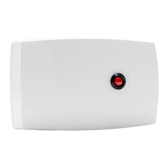
INST ALLA TION GUIDE
1117 Wireless LED Annunciator
Power Supply
Plug Location
Squeeze to
Remove Cover
Figure 1: 1117 Wireless LED Annunciator
Red Annunciator LED
Squeeze to
Remove Cover
Advertisement
Table of Contents

Related Manuals for DMP Electronics 1117


Summary of Contents for DMP Electronics 1117
- Page 1 The 1117 provides a survey capability to allow one person to confirm communication with the receiver while the cover is removed. The 1117 PCB Red Survey LED (see Figure 2) turns on whenever data is sent to the receiver then immediately turns off when the receiver acknowledgement is received.
- Page 2 1117 LED Annunciation Operation The 1117 LED annunciation differs based on whether it is powered by a battery or an optional power supply. When an optional power supply is connected, additional annunciations are available. The following table shows the 1117 LED annunciation operation options.
- Page 3 Optional External 12 VDC Power Supply The 1117 can also be powered from a 12 VDC power supply such as a DMP Model 502-12. Use DMP Model 378 barrel connector with cord, or the equivalent 5.5 x 2.1 mm barrel connector from a local retail outlet and 22 AWG wire to connect to the power supply.
- Page 4 1117 Testing To test the 1117 from a keypad, access the User Menu Outputs On/Off option. The 1117 LED should light within 15 seconds of entering the assigned output number and selecting on. Refer to the XR500/XR100 User's Guide (LT-0683), XRSuper6 User's Guide (LT-0622), XR20 User's Guide (LT-0303), or XR40 User's Guide (LT-0494).
Need help?
Do you have a question about the 1117 and is the answer not in the manual?
Questions and answers