Table of Contents
Advertisement
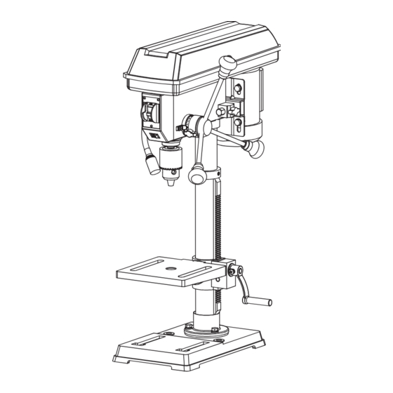
10" Drill Press with Laser
CAUTION: To Reduce The Risk Of Injury, User Must Read
And Understand Operator's Manual. Save These Instructions
For Future Reference.
For questions / comments, technical assistance or repair
parts - Please call toll free at: 1-877-684-8912 (Monday -
Friday 8am - 6pm EST.)
240-3710
OPERATOR'S MANUAL
Page 1
Advertisement
Table of Contents

Related Manuals for Performax 240-3710


Summary of Contents for Performax 240-3710
- Page 1 10" Drill Press with Laser 240-3710 OPERATOR’S MANUAL CAUTION: To Reduce The Risk Of Injury, User Must Read And Understand Operator’s Manual. Save These Instructions For Future Reference. For questions / comments, technical assistance or repair parts - Please call toll free at: 1-877-684-8912 (Monday - Friday 8am - 6pm EST.)
-
Page 2: Table Of Contents
TABLE OF CONTENTS Safety Symbols ................................Page 2 Safety Instructions ............................... Page 3 Overview ..................................Page 10 Speci cations ................................Page 11 Contents ..................................Page 12 Assembly ................................... Page 13 Adjustments ................................Page 17 Operation ................................... Page 21 Maintenance ................................Page 26 Troubleshooting ................................. -
Page 3: Safety Symbols
SAFETY SYMBOLS Some of these following symbols may be used on this tool. Please study them and learn their meaning. Proper interpretation of these symbols will allow you to operate the tool better and safer. Symbol Name Designation / Explanation Volts Voltage Amperes... -
Page 4: Safety Instructions
SAFETY INSTRUCTIONS The purpose of safety symbols is to attract your attention to possible dangers. The safety symbols and the explanations with them deserve your careful attention and understanding. The symbol warnings do not, by themselves, eliminate any danger. The instructions and warnings they give are no substitutes for proper accident prevention measures. WARNING: Be sure to read and understand all safety instructions in this manual, including all safety alert symbols such as “DANGER,”... - Page 5 SAFETY INSTRUCTIONS Safety is a combination of using common sense, staying • Always use safety glasses. Also use face or dust mask alert, and knowing how your drill press works. Read this if cutting operation is dusty, and ear plugs during extended manual to understand this drill press and how to use periods of operation.
- Page 6 SAFETY INSTRUCTIONS • Use the right tool. Don’t force a small tool or attachment PRESSED WOOD PANELS. They can break unexpectedly. If the workpiece is too large to easily support with one hand, to do the job of a heavy-duty tool. Don’t use tool provide an auxiliary support.
- Page 7 SAFETY INSTRUCTIONS the table is tilted, clamp workpiece solidly to the table. speed setting of the drill press. This drill press has ve Use table slots or clamping ledge around the outside spindle speeds. Check spindle speed setting of the drill edge of the table.
- Page 8 SAFETY INSTRUCTIONS laser light. Be aware of the laser light location when using an electric cord having an equipment-grounding conductor the tool. Always make sure that any bystanders in the and a grounding plug. The plug must be plugged into vicinity of use are made aware of the dangers of looking a matching outlet that is properly installed and grounded in directly into the laser.
- Page 9 SAFETY INSTRUCTIONS GUIDELINES FOR EXTENSION CORDS GLOSSARY OF TERMS Use a proper extension cord. Make sure extension cords The safe use of this product requires an understanding of are in good condition. When using an extension cord, be the information on the tool and in this operator’s manual as sure to use a cord that is heavy enough to carry the drawn well as a knowledge of the project you are attempting.
- Page 10 SAFETY INSTRUCTIONS • Feed Handle: Moves the chuck up or down. One or two • Spindle: Shaft rotating on a vertical axis in which the of the handles may be removed if necessary whenever the chuck is attached. workpiece is of such unusual shape that it interferes with •...
-
Page 11: Overview
OVERVIEW Pulley housing cover Head lock set screw Feed return spring and cover Locking screw Belt/pulley speed chart Motor pulley Belt tension Quill lock knob LED light switch Bevel scale Laser Belt Spindle pulley LED worklight Table support Column lock handle Depth tension knob Pulley housing knob Depth scale... -
Page 12: Speci Cations
SPECIFICATIONS 120 V~ 60 Hz 4.1A Motor Pulley speeds 620, 1150, 1630, 2180, 3070 RPM (no load) Laser Wavelength: 650 nm, Max. Output<1 mw Class II LED Light Table size 7 1/4 x 7 1/ 4 in. (18.4 x 18.4 cm) Base size 13 3/8 x 8 1/4 in. -
Page 13: Contents
CONTENTS The following items are included with your drill press: PART DESCRIPTION QUANTITY PART DESCRIPTION QUANTITY Head Assembly Column/Support Assembly Base Rack Collar Table/Support Assembly Flat Washer 8 Support Lock Handle Spring Washer 8 Chuck Hex Bolts M8 x 25 Feed Handle 4mm Hex Key Rack... -
Page 14: Assembly
ASSEMBLY UNPACKING YOUR DRILL PRESS Do not use this product if any parts of the package contents are already assembled to your product when you unpack it. Package contents are not assembled to the product by the manufacturer and require customer installation. Use of a product that may have been improperly assembled could result in serious personal injury. - Page 15 ASSEMBLY spring washer 8 (E) in each column support hole and tighten with the wrench. TABLE TO COLUMN (Fig. 3a-3c) FIG. 3a • Insert the rack (A) into the geared groove of the table support (B). Make sure the worm shaft (C) on the inside of table support is engaged with the teeth of the rack.
- Page 16 ASSEMBLY DRILL PRESS HEAD TO COLUMN (Fig. 4) FIG. 4 • Lift the drill press head assembly (A) carefully and place the mounting hole of the drill press head onto the top of the column (B). Make sure the head is seated properly on the column.
- Page 17 ASSEMBLY INSTALL THE CHUCK (Fig. 7) FIG. 7 • Inspect and clean the taper hole in the chuck (A) and the spindle (B). Remove all grease, coatings, and particles from the chuck and spindle surfaces with a clean cloth. • Open the chuck jaws (C) by turning the chuck barrel clockwise by hand.
-
Page 18: Adjustments
ADJUSTMENTS WARNING: FIG. 9 To prevent personal injury, always disconnect the plug from the power source when making any adjustment. ASSEMBLY ADJUSTMENTS INSTALL THE BELT (Fig. 9) • Open the pulley housing cover. • Loosen the belt tension lock knobs (A) on both sides of the drill press. - Page 19 ADJUSTMENTS ADJUST SPEEDS AND TENSION THE FIG. 11 BELT (Fig. 11) • Open the drill press pulley housing cover. • Loosen the belt tension knobs (A) on both sides of the drill press head. • Pull the motor (B) towards the drill press head. •...
- Page 20 ADJUSTMENTS TO SQUARE THE TABLE TO THE HEAD FIG. 14 (Fig. 14) • Insert a 3 in. (7.6 cm) drill bit (A) into the chuck (B) and tighten. • Raise and lock the table (C) about 1 in. (2.5 cm) from the end of the drill bit.
- Page 21 ADJUSTMENTS ANGULAR PLAY OF THE SPINDLE FIG. 17 (Fig. 17) Move the spindle to the lowest downward position and hold in place. With your other hand, try to make it revolve around its axis with a side motion. If there is too much play, proceed as follows: •...
-
Page 22: Operation
OPERATION WARNING: RISK OF PERSONAL INJURY. NEVER PERFORM ANY DRILLING OPERATION FREEHAND (WITHOUT WORKPIECE AGAINST THE TABLE). The bit could grab the workpiece if it slips or twists. WARNING: RISK OF PERSONAL INJURY. ALWAYS DISCONNECT THE TOOL FROM THE POWER OUTLET BEFORE MAKING ANY ADJUSTMENT, INSTALLING OR CHANGING BITS OR OTHER TOOLS. - Page 23 OPERATION LASER LIGHT SWITCH (Fig. 21) FIG. 21 WARNING: LASER RADIATION HAZARD. Do not stare into the beam. Use of controls or adjustments or performance of procedures other than those speci ed in this instruction manual may result in hazardous radiation exposure.
- Page 24 OPERATION POSITION THE TABLE AND WORKPIECE FIG. 23 (Fig. 23) Always place a piece of backup material (A) (wood, plywood, etc.) on the table underneath the workpiece (B). This will prevent splintering on the underside of the workpiece as the drill bit breaks through.
- Page 25 OPERATION WORKPIECE METHOD (Fig. 24) FIG. 24 • Mark the desired depth of the hole on the side of the workpiece (A). • With the switch off, bring the drill bit (B) down until the tip is even with the mark. •...
- Page 26 OPERATION DRILLING METAL • Use metal-piercing twist drill bits. • It is always necessary to lubricate the tip of the drill with oil to prevent overheating the drill bit. • All metal workpieces should be clamped down securely. Any tilting, twisting, or shifting causes a rough drill hole and increases the potential of drill bit breakage.
-
Page 27: Maintenance
MAINTENANCE WARNING: To reduce the risk of injury, turn power switch off and remove plug from the power source outlet before doing maintenance on or lubricating your drill press. CAUTION: Certain cleaning agents and solvents damage plastic parts. Some of these are: gasoline, carbon tetrachloride, chlorinated cleaning solvents, ammonia and household detergents that contain ammonia. -
Page 28: Troubleshooting
TROUBLESHOOTING PROBLEM PROBLEM CAUSE CORRECTIVE ACTION Noisy operation • Incorrect belt tension • Adjust tension • Dry spindle • Remove spindle/quill assembly lubricate • Loose pulley • Tighten pulley • Bad bearing • Replace bearing Excessive drill wobble • Loose chuck •... -
Page 29: Replacement Parts List
REPLACEMENT PARTS LIST For questions / comments, technical assistance or repair parts - Please call toll free at: 1-877-684-8912 (Monday - Friday 8am - 6pm EST.) PART DESCRIPTION PART# PART DESCRIPTION PART# Support Lock Handle 24037100001 4mm Hex Key 24037100006 Feed Handle 24037100002 Chuck Key... -
Page 30: Warranty
WARRANTY TWO-YEAR LIMITED WARRANTY: If, during normal use, this PERFORMAX™ power tool breaks or fails due to a defect in material or workmanship within two years from the date of original purchase, simply bring this tool with the original sales receipt back to your nearest Menards™...
Need help?
Do you have a question about the 240-3710 and is the answer not in the manual?
Questions and answers