
Related Manuals for LEGRAND Raritan PX4


Summary of Contents for LEGRAND Raritan PX4
- Page 1 PX4 User Guide Copyright © 2023 Legrand PDU_G4_UG_B1_4.0.40 April 2023 Release 4.0.40...
-
Page 2: Table Of Contents
Contents Introduction to Xerus Technology Platform Safety Instructions............... 10 Safety Guidelines. - Page 3 Releasing a Link Unit..............39 Switching to a Different Unit.
- Page 4 Supported Web Browsers and Mobile Devices..........103 Login, Logout and Password Change.
- Page 5 Peripherals................163 Yellow- or Red-Highlighted Sensors.
- Page 6 Using Prometheus and Grafana............333 Requirements for Prometheus and Grafana.
- Page 7 With HyperTerminal..............371 With SSH or Telnet.
- Page 8 Reliability Data..............403 Reliability Error Log.
- Page 9 VCCI Information (Japan) Legrand is not responsible for damage to this product resulting from accident, disaster, misuse, abuse, modification of the product, or other events outside of Legrand's reasonable control or not arising under normal operating conditions. If a power cable is included with this product, it must be used exclusively for this product.
-
Page 10: Introduction To Xerus Technology Platform
Introduction to Xerus Technology Platform The Xerus Technology Platform combines hardware and software technologies embedded in our power solutions. It drives data center efficiency by delivering security, high compute power, advanced alerting, and complete visibility into your power chain. With Xerus cyber-resilient intelligence, your team receives actionable data to aid in decisions that help safeguard assets and maximize your data center continuity and performance. -
Page 11: Safety Guidelines
Safety Guidelines WARNING! Before installing or operating this product, read and understand all sections in this guide. WARNING! Connect this product to an AC power source with a voltage that is within the range specified on the product's nameplate. Operating this product outside the nameplate voltage range may result in electric shock, fire, personal injury and death. - Page 12 WARNING! If this product is a model that requires the assembly of the line cord or plug, the assembly must be performed by a licensed electrician, and the line cord or plugs used must be rated based on the product's nameplate ratings, as well as national and local electrical codes.
-
Page 13: Before You Begin
Before You Begin Before beginning the installation, perform the following activities: • • Unpack the product and components • • Prepare the installation site • • Check the branch circuit rating • • Fill out the equipment setup worksheet Unpacking the Product and Components 1. - Page 14 With APIPA, your PX4 automatically configures a link-local IP address and a link-local host name when it cannot obtain a valid IP address from any DHCP server in the TCP/IP network. Only IT devices connected to the same subnet can access the PX4 using the link-local address/host name. Those in a different subnet cannot access it. Exception: Port Forwarding mode does not support APIPA.
-
Page 15: Rackmounts
Rackmounts In This Chapter Circuit Breaker Orientation Limitation........15 Rackmount Safety Guidelines. -
Page 16: Initial Installation And Configuration
Initial Installation and Configuration This chapter explains how to install your device and configure network connectivity. In This Chapter Connecting the PDU to a Power Source........16 Connecting to Your Network. -
Page 17: Dual Ethernet Connection
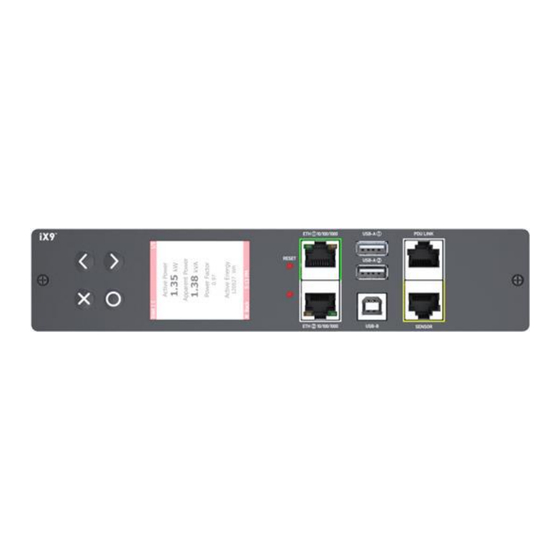
Warning: Accidentally plugging an RS-232 RJ-45 connector into the Ethernet port can cause permanent damage(s) to the Ethernet hardware. Dual Ethernet Connection Models with two Ethernet ports may have ports supporting different speeds. Note if your Ethernet port is marked with speed. Port layouts and labels may vary by model. •... -
Page 18: Connecting A Mobile Device
▶ Configuration via a connected computer: 1. Connect the PX4 to a computer. 2. Use the connected computer to configure via the command line or web interface. • Command line interface: See Initial Network Configuration via CLI. • • Web interface: Launch a web browser on the computer, and enter the link-local IP address or •... - Page 19 ▶ Step B: Connect the mobile device to PX4 1. Get an appropriate USB cable for your mobile device. • iOS: Use the regular USB cable shipped with your iOS mobile device. • • Android: Use a USB OTG adapter cable. •...
- Page 20 Note: PDView also shows the 'Disconnected' status during the firmware upgrade. If so, wait until the firmware upgrade finishes. b. The PDView shows the "Connected" message when it detects the connected PX4. 2. If the factory-default login credentials remain unchanged, or if PDView has been configured with accurate login credentials, PDView automatically logs in to the web interface.
-
Page 21: Saving User Credentials For Pdview's Automatic Login
Tip: You can store the updated "admin" or other user credentials in PDView so that automatic login always functions properly upon detection of the PX4. Saving User Credentials for PDView's Automatic Login When PDView detects PX4 for the first time, it automatically attempts to log in with the factory-default user credentials. - Page 22 4. The user credentials setup page opens. • Per default, three administrator user credentials are pre-configured for three Legrand brands: • ▪ Raritan ▪ ▪ Legrand ▪ ▪ Server Technology ▪ 5. Modify existing user credentials or type new ones, and tap Save. The pre-configured admin...
-
Page 23: Connecting To A Computer
Connecting to a Computer The PX4 can be connected to a computer for configuration via one of the following ports. • • Ethernet ports • • USB-B port To use the command line interface (CLI) for configuration, establish a USB connection. To use a web browser for configuration, make a network connection to the computer. -
Page 24: Bulk Configuration Methods
Bulk Configuration Methods If you have to set up multiple devices, you can use one of the following configuration methods to save time. ▶ A bulk configuration file downloaded from PX4: • • Requirement: All devices to configure are of the same model and firmware. •... -
Page 25: Best Practices For Cascading
The first one in the cascade is the primary device and all the other devices follow it in the cascade. Only the primary device is physically connected to the LAN -- wired or wireless. Each device in the cascade is accessible over the network, with Bridging or Port-Forwarding cascading mode activated on each device. -
Page 26: Power-Sharing Restrictions And Connection
▶ When to establish a chain comprising 32 devices: A chain consisting of 32 devices saves the most Ethernet connections and costs, and it is recommended only when: • • External Ethernet ports are expensive or limited. • • Available IP addresses are limited. ▶... -
Page 27: Power Sharing Port On Ix9 Controllers
▶ Events that occur when entering power-sharing mode: • • The power supply sensor enters the fault state. Tip: You can set an event rule for sending a notification when this sensor enters the fault state. • • The above event is logged in the internal event log. ▶... - Page 28 Note: The latest generation of DX2-DH2C2 does NOT have this restriction and can have SouthCo H3- EM series connected in the power-sharing mode. • • A maximum of 2 door handles connected to a maximum of one DX2-DH2C2 are supported. •...
-
Page 29: Linking Units
Linking Units The Linking feature allows the linking configuration of a single Primary unit to multiple link units so that you can view and manage them all in one place. The primary unit has full knowledge of the location of the connected link units, as well as the power and/or environmental information of all link units. - Page 30 When the chain is established with a single primary unit, and one or more link units, communication occurs with the primary unit through its IP address. The primary unit, in turn, communicates to the other link units in the chain through their individual IP addresses, which optimizes monitoring and management.
- Page 31 ▶ What user privileges are required for managing the Linking configuration? Administrative privileges are required for both the primary unit and link unit. To add a link, your administrative login account is required, but after that you only log in to the primary to manage the chain, as all link units in the chain are visible in the user interface from the primary unit view.
-
Page 32: Linking In The Web Interface
Firmware version must match between primary units and link units to function normally. If the primary unit is updated before the link units, for example, you will see a "Firmware version mismatch" message in the Link Units section. When this occurs, link unit data will not display. You will not be able to switch to the mismatched link unit. -
Page 33: Options For Adding Link Units
4. MAC address 5. Rating 6. Link to Data Log The ID of the primary unit is automatically assigned the ID "1", as shown in the example as "My PDU (1)". The ID cannot be edited. Options for Adding Link Units To start configuring the Primary Unit with Link Units, your options in the web interface depend on the network and physical configuration of units. - Page 34 ▶ To add a link unit: • • Primary and link units must be the same model, running the same firmware versions. 1. Log in to the primary unit and go to the PDU page. 2. Click Add Link Unit. The following add box displays: 3.
-
Page 35: Linking Cascaded Units
About the Link ID The Link ID "1" is automated and reserved internally for the primary unit. The primary unit’s ID "1" cannot be edited. The Link ID "2-8" is available for you to select as the ID for each of the link units you add to the chain. From the Link ID drop-down, you can select the desired Link ID to manage the link units in the chain. - Page 36 The Custom settings option requires that you to select each cascaded unit by its node number, and map it to a Link ID manually. You must also select a hostname type for each link. The linking process follows your customized list and attempts to add all selected expansion units.
- Page 37 6. Click Link to start the linking process. The table shows progress and then final results. In the example below, expansion unit 1 was linked successfully. Expansion unit 2 failed--the connection may have failed, or this result may also indicate there was no unit at that position. Expansion units 3-7 were skipped because the process stops upon first failure.
- Page 38 ▶ To link cascaded units (Custom method): 1. On the PDU page, click the Link Cascaded Units button. The Link Cascaded Units dialog opens. 2. Enter the Primary Unit's administrator user name and password. 3. Select Custom Settings. 4. Click Append Node to add a row to the table, then complete each field in the row to describe how the expansion unit should be linked.
-
Page 39: Primary Units Manage Link Units
Primary Units Manage Link Units The primary unit manages the following functions for the entire chain of linked units: • • User management and authentication – configured only on the primary. • • Date and time – the primary synchronizes its date and time settings to link units. If NTP is not used, then the synchronization interval is every 10 minutes. -
Page 40: Switching To A Different Unit
▶ To release a link unit from the Primary Unit's web interface: Note: If a release action is attempted on a link unit when the unit is an unreachable state, a warning message displays, and the primary will not recognize the link unit. 1. -
Page 41: Re-Linking A Link Unit
▶ To switch to a different unit: 1. Click the Switch control. 2. Select one of the link units from the drop-down list. Link number "2-8" appears in parentheses. 3. The page displays data for the selected link unit. 4. To return to the page for the primary, select the primary unit. Primary number "1" appears in parentheses. - Page 42 ▶ Dashboard The Dashboard shows inlets, OCPs, alerted sensors, and inlet history for the entire linked chain. In this example, data for the single inlet of the primary "My PDU (1)" Inlet I1, and the inlet of the link unit "My PDU (2)" Inlet I1, are displayed together. The OCPs for the units are also available together on the Dashboard page.
- Page 43 ▶ Inlets Page On the Inlets page, the primary unit and link units are displayed together on the same page. In this example, data for the single inlet of the primary "My PDU (1)" Inlet I1, and the inlet of the link unit "My PDU (2)"...
- Page 44 ▶ Viewing Outlets for Link Units On the Outlets page, you can switch from the primary to the link. 1. From the Outlets page drop-down, select the link unit "My PDU (2)". Note: To view outlets for a specific link unit, the link unit must be selected by name. All outlets of the link unit display for viewing and access exactly like the outlets of the primary unit.
- Page 45 2. You can switch back to the primary unit by selecting "My PDU (1)". Note: The Switch control is only available when there is at least one link unit in the chain; otherwise, the page defaults to displaying only the outlets of the primary. 3.
-
Page 46: Outlet Groups
Outlet Groups An outlet group is a named collection of selected outlets. When user-defined, an outlet group can contain outlets from different PDUs, including both primary and link units. Outlet groups support fast and efficient outlet control actions (On, Off, Power Cycle) across multiple PDUs, and with PDU Linking, member outlets for the primary and its link units can be collected in the same outlet group. - Page 47 ▶ Viewing Outlet Group Details Click an outlet group name in the list to display operations details for the outlet group. From this page, you can issue the outlet control actions On, Off, and Cycle (power cycling to restore the outlet) for all member outlets in the outlet group.
- Page 48 ▶ To add an outlet group: 1. On the Outlet Groups page, click Add Group. The New Outlet Group page displays, defaulting to the outlets in the primary unit. 2. Type a name for the new outlet group. 3. Select individual member outlets for the primary as shown in the default page, or to select all outlets for the primary, select My PDU (1).
-
Page 49: Pairwise Outlet Groups
The following example shows the outlet group named "TEST 1" with all outlet members selected for the primary unit and outlet members 1-6 selected for the link unit. Controlling Outlets in Groups 1. From the Outlet Groups page, select an outlet group by name. 2. - Page 50 PDU 1 (Primary Unit) Server Load PDU 2 (Link Unit) Outlet 1 Server 1 Outlet 1 Outlet 2 Server 2 Outlet 2 Outlet 3 Server 3 Outlet 3 … … … Outlet 20 Server 20 Outlet 20 Using the above example, to control power to a server, you would typically switch one outlet of PDU 1 and one outlet of PDU 2.
-
Page 51: Ocps Page
OCPs Page Overcurrent protectors from both primary and link PDUs are displayed together on the same OCPs page. If sensors are present on the units, sensor data for both primary and link units will also appear on the page. Peripherals Page The Peripherals Page shows peripheral devices connected to the primary or link unit. -
Page 52: Pdu Linking At The Rack
PDU Linking at the Rack PDUs with the iX9 controller have a PDU Link port that supports directly connecting two same model, same firmware version PDUs in a primary-link configuration right at the rack. This connection also allows for power-sharing between the two PDUs. To allow PDU linking of the connected PDUs, complete the configuration using the PDU front panel display of the Primary unit. -
Page 53: Displays For Primary And Link Units
• Select No to deny PDU Linking for these 2 PDUs. The message will not appear again. • 4. Upon selecting Yes, the units will be linked as Primary and Link units, and will operate as other PDU Linking configurations. Displays for Primary and Link Units Each unit in a PDU Linking chain displays its own PDU data (inlets, outlets, sensors, alerts, etc.) ▶... - Page 54 ▶ Link units: 1. No display of alarms/events. 2. PDU information shows the primary IP address...
-
Page 55: Linking In The Cli
Linking in the CLI For each unit in a chain, you can list the units, switch to a different unit, add a new link unit, and release a link unit. You can then use all regular commands as usual to access and control individual units, as with any standalone unit. - Page 56 • • Link ID • • Communication status (for link unit only) • • Device name • • Model name • • Serial number • • Firmware version # pdu list ▶ Switch Unit Switch between the primary and link units. The Link ID must be 1 (primary) or 2-8 (link units). # pdu [id] ▶...
-
Page 57: Using The Hardware Features
Using the Hardware Features Xerus firmware runs on various hardware designs, including different sizes and controllers. In This Chapter Inlet..............57 Outlets and Outlet LEDs. -
Page 58: Connection Ports
Outlet OFF and suspended after OCP trip Red blinking OCP tripped: Outlet OFF Red/Green blinking OCP tripped: Outlet ON Red/Yellow/Green blinking Boot Up Sequence: Firmware is loading Connection Ports Connection ports vary by model. PX4 Series Connection Ports PX4 Series models have the following ports: •... -
Page 59: Connection Port Functions
Connection Port Functions Port Used for... • • Cascading devices for sharing a network connection. USB‑B • • Establishing a USB connection with a computer for: • Using the command line interface. • • Performing disaster recovery with Technical Support. •... -
Page 60: Automatic And Manual Modes
Use the front panel display to view information and even administer features on supported models. It consists of: • • LCD display • • Four control buttons Zero U models automatically adjust the orientation of the content shown after detecting the direction of installation. -
Page 61: Operating The Front Panel Display
Button Function Down Back -- OR -- Switch between automatic and manual modes Operating the Front Panel Display Enter manual mode when you want to operate the front panel display. ▶ Color changes of the display's top and bottom bars: •... - Page 62 Screen with black bars Main Menu Main Menu The Main Menu commands depend on the model. The system time and the X and O buttons and their action on each page are shown at the bottom of the display. For example, "X Auto" means you can press the X button to enter automatic mode. "Select O" means you can press O to select an option.
- Page 63 • • Numeric sensors in the warning or critical range of an enabled threshold. • • Alarmed state sensors • • Tripped circuit breakers or blown fuses If there are no alerted sensors, the display shows the message "No Alerts." ▶...
- Page 64 Number Description Sensor readings and/or states. A numeric sensor shows both the reading and state. A state sensor or actuator shows the state only. Available states: • • Alarmed • • Lower Critical = below lower critical • • Lower Warning = below lower warning •...
- Page 65 b. (Optional) If the alarm occurred more than one time, the numbers of current page and total pages are shown in the top-right corner, similar to the above diagram. Press to view the information of other occurrences. c. To acknowledge all alarms now, press Depending on model, the PDU menu includes internal beeper states, unit-level power and energy readings (for models with multiple inlets), Energy pulse output settings, and power supply status.
- Page 66 2. Use the arrow buttons to view additional pages of details: ▶ PDU Link Status: If Link PDUs are connected, a Link PDUs page appears with details.
- Page 67 ▶ Internal beeper state: • • Active or Off. • In the Active state, the reason of turning on the beeper is indicated, and the top/bottom bars • turn red. To mute the beep sound immediately, press ▶ Energy pulse output Models that support Energy Pulse have an LED Energy Pulse Status page.
- Page 68 To change the energy pulse settings, press for Setup, then select to enable or disable the feature. Note: All outlet LEDs turn OFF after enabling the energy pulsing. You still can turn on or off outlets during the pulsing period though outlet LEDs do not change their status. ▶...
- Page 69 ▶ Muting the Internal Beeper After enabling the internal beeper's mute control function, you can choose to mute the beeper via the front panel whenever the beeper sounds for an alarm. By default, the beeper's mute control feature via front panel is enabled. ▶...
- Page 70 2. Press for Mute, then confirm the operation by selecting Yes. 3. The beeper stops, and the Beeper State shows "Active (Muted)".
- Page 71 Inlet Inlet details display over multiple pages. ▶ To show the inlet information: 1. Select "Inlet I1" in the Main Menu, and press • Models with one inlet, the first page of details shows immediately. • • Models with more than one inlet, use the arrow buttons to select the inlet you want to view, then •...
- Page 72 • • Phase angle • • Crest factor • • Voltage/current total harmonic distortion ▶ Three Phase Inlet Details: A three phase inlets shows the following readings over multiple pages. Use the arrow keys to go to each page. Use the arrow buttons to scroll between the pages. •...
- Page 73 • • Voltage L1-L2 • • Voltage L2-L3 • • Voltage L3-L1 • • Frequency • • Unbalanced Voltage • • Voltage L1-N • • Voltage L2-N...
- Page 74 • • Voltage L3-N • • Frequency • • Unbalanced Voltage • • L1, L2, and L3: • Crest Factor • • Current THD (total harmonic distortion) • • Voltage THD (total harmonic distortion) •...
- Page 75 OCPs If your model has more overcurrent protectors (OCPs) than the display can show at a time, a page number appears in the top‑right corner of the display. Use the arrow buttons to scroll through the pages. ▶ To show the overcurrent protector information: 1.
- Page 76 ▶ To show an outlet's information: 1. Select "Outlets" in the Main Menu, and press 2. The list of outlets is shown with their receptacle types, current values (A), and power states which are indicated by the colors of circles. The currently-selected outlet number and total of outlets are indicated in the top-right corner of the display.
- Page 77 • Active Power • • Active Energy • • Reactive Power • • Apparent Power • • Apparent Energy • • Power Factor • • Phase Angle •...
- Page 78 • Current • • Voltage • • Frequency • • Crest Factor • • Current THD (total harmonic distortion) • • Voltage THD (total harmonic distortion) • ▶ Power Control This section applies to outlet-switching capable models only. The front panel outlet control must be enabled for performing this power control function. The default is to disable this function.
- Page 79 • In the individual page for the outlet, press • for Switch to go to the power control page. In this example, the outlet is On, so the available options are 'Switch Off' and Cycle. 3. Use the arrow buttons to select the desired option, and press...
- Page 80 • Switch Off: Turn off the outlet. • • Switch On: Turn on the outlet. • • Cycle: Power cycle the outlet. The outlet is turned off and then on. • 4. A confirmation message appears. Select Yes or No, and then press 5.
- Page 81 The currently-selected outlet group's number and total of outlet groups are indicated in the top-right corner of the display. • Gray circle: All outlets are OFF • • Green circle: All outlets are ON • • Half Green/Half Gray circle: Some outlets are ON, and some outlets are OFF. •...
- Page 82 ▶ To power on, off or cycle an outlet group: 1. Select "Outlet Groups" in the Main Menu, and press • The LCD display shows a list of outlet groups. • 2. Select an outlet group, and press to go to the Outlet Group's details page. •...
- Page 83 ▶ To show environmental sensor or actuator information: 1. Select "Peripherals" in the Main Menu, and press 2. The display shows a list of environmental sensors/actuators. • When the list exceeds one page, the currently-selected sensor/actuator's ID number and total of •...
- Page 84 Number Description Sensor or actuator states: • • n/a = unavailable • • Normal • • Alarmed • • Lower Critical = below lower critical • • Lower Warning = below lower warning • • Upper Warning = above upper warning •...
- Page 85 Number Description The following information is listed. • • Serial number • • Chain position, which involves the following information: • • Port <N>: <N> is the number of the sensor port where this sensor or actuator is connected. • •...
- Page 86 2. Press to turn on or off the actuator. A confirmation message similar to the following is shown. 3. Use the arrow buttons to select Yes or No, and then press 4. Verify that the actuator status shown has been changed. Device Info The display shows the device's information, network and IPv4/IPv6 settings through various pages.
- Page 87 ▶ To show the device information: 1. Use the arrow buttons to select "Device Info" in the Main Menu, and press 2. Device information for your model displays. • Device name. • • Firmware version, model name and serial number. •...
- Page 89 Description Cascading status, which can be one of the following: • • No Cascading: This device's cascading mode is set to None. • • Network Bridge Enabled: This device's cascading mode is set to Bridging. Its IP address is also displayed on this page. •...
- Page 90 Number Description IPv4/IPv6 network information, including: • • Network configuration: DHCP (or Automatic), or Static. Static represents Static IP. • • IP address. • • Prefix length, such as "/24". Note: If you disable any Ethernet interface, a message 'Interface Disabled' is shown.
-
Page 91: Alerts Notice In A Yellow Or Red Screen
-- OR -- Alerts Notice in a Yellow or Red Screen In the automatic mode, if an alert occurs, the LCD display automatically shows a yellow or red screen which indicates the total number of alerted sensors and information on the latest transitions. •... - Page 92 ▶ When there are only alerted sensors -- NO ALARMS are present: Number Description The total of alerted sensors in critical and warning levels. A list of alerted sensors. The latest reading/status time related to each alerted sensor. ▶ When there is any alarm present: The display shows the alarm(s) and the available command in the bottom-right corner is 'Actions'.
- Page 93 ▶ Available operations: • • For alerted sensors only, press to view a list of all alerted sensors. You do not have to acknowledge alerted sensors. • • When an alarm is present, press to view the options. Use the arrow buttons to select an option, and press •...
-
Page 94: Port Overload - Reset Fuse
Port Overload - Reset Fuse If an overload condition is detected on an external port, an alert notification is displayed in the front panel. The notification includes a list of ports that may have caused the overload. This alert cannot be dismissed without resolving the overload condition and resetting the fuse. ▶... -
Page 95: Manually Changing Zero U Lcd Orientation
In the end, a message appears, indicating whether the firmware upgrade succeeds or fails. Manually Changing Zero U LCD Orientation A Zero U model has a tilt sensor that can detect the orientation of its physical device to automatically adjust ts LCD content's orientation. If the LCD's orientation does not meet your need, you can manually configure it. -
Page 96: Resetting The Button-Type Circuit Breaker
If a circuit breaker switches off power, the front panel display shows open. To find which circuit breaker is open (trips), select Alerts or OCPs in the front panel display menu. When a circuit breaker trips, power flow ceases to all outlets connected to it. You must manually reset the circuit breaker so that affected outlets can resume normal operation. -
Page 97: Fuse
3. Examine your PX4 and the connected equipment to remove or resolve the cause that results in the overload or short circuit. This step is required, or you cannot proceed with the next step. 4. Pull up the operating handle until the colorful rectangle or triangle turns RED. Fuse Some devices may be implemented with fuses instead of circuit breakers. - Page 98 2. Verify the new fuse's rating against the rating specified in the fuse holder's cover. 3. Push the cover of the fuse holder to expose the fuse. 4. Take the fuse out of the holder.
-
Page 99: Fuse Replacement On 1U Models
5. Insert a new fuse into the holder. There is no orientation limit for fuse insertion. 6. Close the fuse holder and the hinged cover in a reverse order. Fuse Replacement on 1U Models On the 1U model, a fuse is installed in a fuse knob, which fits into the PDU's fuse carrier. Number Description Fuse carrier... - Page 100 b. Take this knob out of the fuse carrier. 3. Remove the original fuse from this knob, and insert either end of a new one into the knob. Make sure the new fuse's rating is the same as the original one. Number Description Fuse knob...
-
Page 101: Beeper
Number Description INAPPROPRIATE installations Appropriate installation 6. Connect the PDU's power cord to the power source and verify that the corresponding fuse LED is lit, indicating that the fuse works properly. Beeper The PX4 includes an internal beeper to issue an audible alarm for an overcurrent protector which is open. -
Page 102: Threaded Grounding Point
3. Get a new controller and install it back into the PDU in the reverse order. Threaded Grounding Point Some models have a threaded grounding point. Identify it via the grounding symbol: Wire this point to an electrical system to protectively ground the PX4. -
Page 103: Using The Web Interface
Using the Web Interface This chapter explains how to use the product web interface for administration. In This Chapter Supported Web Browsers and Mobile Devices......103 Login, Logout and Password Change. -
Page 104: Changing Your Password
▶ To log in to the web interface: 1. In a supported browser go to the IP address of your PX4 • If the link-local addressing has been enabled, you can type pdu.local instead of an IP address. • 2. If any security alert message appears, accept it. 3. -
Page 105: Web Interface Overview
▶ Password requirements: • Case sensitive. • • 4 to 64 characters. • ▶ Password change required on first login: • • On first login, password change is forced and strong passwords are enabled by default. The new password must be at least 8 characters and contain at least one upper case letter, one lower case letter, and one digit. - Page 106 Number Web interface element Menu - Not all models support all menu options. Data/setup page of the selected menu item. • • Left side: - PX4 device name. • • Right side: - Displayed language, which is English (EN) by default. You can change it. - Your login name, which you can click to view your user account settings.
-
Page 107: Menu
Number Web interface element - Click Last Login to view your login history. • • PX4 system time, which is converted to the time zone of your computer or mobile device. - Click Device Time to open the Date/Time setup page. Menu Depending on your model and hardware configuration, your PX4 may show all or some menu items shown below. -
Page 108: Quick Access To A Specific Page
Menu Information shown User Management Data and settings of user accounts and groups, such as password change. Device Settings Device-related settings, including network, security, system time, event rules and more. Maintenance Device information and maintenance commands, such as firmware upgrade, device backup and reset. -
Page 109: Dashboard - Inlet I1
▶ PDU Totals • • For multi-inlet models or in‑line monitors PDU Totals sum up the total active power and active energy. Dashboard - Inlet I1 The number of phases shown in the Inlet section is model dependent. ▶ Link to the Inlet page: To view more information or configure the inlet(s), click this section's title 'Inlet I1' to go to the Inlet page. - Page 110 ▶ Left side - generic inlet power data: The left side lists all or some of the following data. Available data is model dependent. • • Active power (kW or W) • • Apparent power (kVA or VA) • • Active energy (kWh or Wh) •...
-
Page 111: Dashboard - Ocp
• • RMS current (A) and rated current • The smaller, gray text adjacent to RMS current is the rated current. • • • A bar showing the RMS current level • • RMS voltage (V) The RMS current bars automatically change colors to indicate the current status according to your configured thresholds. -
Page 112: Dashboard - Alerted Sensors
▶ Each OCP's power data: OCP data from top to bottom includes: • • RMS current (A), and rated current • Smaller gray text adjacent to RMS current is each OCP's rated current, such as "16A" shown in • the above diagram. •... -
Page 113: Dashboard - Inlet History
To view detailed information or configure each alerted sensor, click each sensor's name to go to individual sensor pages. See Individual Sensor/Actuator Pages (on page 173). ▶ Summary in the section title: Information in parentheses adjacent to the title is the total number of alerted sensors. For example: •... - Page 114 • To retrieve the exact data at a particular time, hover your mouse over the data line in the chart. • Both the time and data are displayed as illustrated below.
- Page 115 ▶ Inlet selection on multi-inlet models: If your PDU is a multi-inlet model, you can have one or multiple inlets show their power charts by selecting the checkbox(es) of the desired inlet(s). • • When multiple inlets are displayed in the chart, their colors differ. You can identify each inlet's data according to the colors of the selected inlet checkboxes.
-
Page 116: Dashboard - Alarms
• • When both inlets are shown in the chart, simply hover your mouse over either inlet's data line. Both inlets' values display simultaneously, marked with corresponding colors. Dashboard - Alarms If configuring any event rules which create or emit device alarms, the Alarms section will list any event that hasn't been acknowledged yet. - Page 117 ▶ To acknowledge an alarm: • • Click Acknowledge, and that alarm then disappears from the Alarms section. This table explains each field of the alarms list. Field Description Name Custom name of the Alarm action. Reason Shows the log message if the alarm was only triggered by one specific event.
-
Page 118: Pdu
Tip: You can also acknowledge all alarms in the front panel display. Generic information and PDU settings are available on the PDU page. To open the PDU page, click 'PDU' in the Menu. ▶ Device information shown: • • Firmware version •... - Page 119 Selects an operating mode to determine Latching Relay Behavior (on page 121). on power loss the latching relay behavior when PDU • • PXO, PXC and Legrand PDU do not support power is lost. Latching Relays. • • Options: Non-latching and Latching •...
- Page 120 Field Function Note *Trip cause outlet If an outlet is suspected to have caused an Suspended outlets are not turned back on when the handling OCP trip event, it can optionally be marked OCP is closed. as "Suspended" and handled differently. Trip Cause Outlet Handling (on page 123).
-
Page 121: Latching Relay Behavior
For a regular model with multiple inlets: • • Total active energy = sum of all inlets' energy values • • Total active power = sum of all inlets' active power values For an in‑line monitor with multiple inlets/outlets: • •... -
Page 122: Options For Outlet State On Power Up
▶ Non-Latching Mode: • • Relay always opens when power is lost. This insures all relays are open when power is applied to the PDU. • • Always select this mode if the combined inrush current of the devices connected to the PDU trip circuit breakers when power is applied to the PDU. -
Page 123: Initialization Delay Use Cases
Option Function last known Restores the outlet(s) to the previous power state(s) before the PX4 was powered off. When configuring an individual outlet, there is one more outlet state option. Additional option Function PDU defined (on/off/last- Follows the global outlet state setting, which is set on known) the PDU page. -
Page 124: Time Units
• • once the respective OCP is closed, the outlet is not turned on again • • outlet state shows as 'suspended' in the web interface and the CLI • • warnings are shown when you attempt to turn on a suspended outlet •... -
Page 125: Power Supply Sensor
3. Click a sensor to edit the thresholds. 4. Make changes as needed. • To enable any threshold, select the corresponding checkbox. • • Type a new value in the accompanying text box. • 5. Click Save. Power Supply Sensor The PX4's controller receives power from its inlet. -
Page 126: Inlet
State Description fault The controller cannot receive power from its own inlet because of a power failure on the inlet or a broken power supply. Instead it is receiving power from another PX4 PDU. Power-Sharing Restrictions and Connection (on page 26). After entering the fault state, this sensor is listed in the Alerted Sensors section of the Dashboard. - Page 127 ▶ Dip Event Waveform Example: ▶ Swell Event Waveform Example:...
- Page 128 ▶ To configure dip/swell thresholds: 1. On the Inlet page, click Edit Thresholds in the Dip/Swell section to enable the form. 2. Dip threshold: Select the checkbox to enable the threshold. Enter a voltage value. The default is set to enabled, and the value is relative to the inlet's voltage rating. 3.
- Page 129 • Crest Factor • • Displacement Power Factor • • Phase Angle • ▶ Settings--Name the inlet: Scroll down past the Sensor list to the Settings. • • Click Edit Settings, enter a name for the inlet, then click Save. For example, name the inlet after the power source.
- Page 130 Tip: To enable the display of minimum/maximum for any sensor, click the Options icon at the top right of the Sensors lists. • • Click Reset and then confirm in the message. This inlet's sensor's minimum and max values are reset. ▶...
-
Page 131: Configuring A Multi-Inlet Model
▶ To configure inlet thresholds: By default, there are pre‑defined RMS voltage and current threshold values in related fields. You can modify them to meet your needs. 1. Click the Thresholds title bar at the bottom of the page to display inlet thresholds. 2. - Page 132 2. Now you can configure the selected inlet, such as enabling thresholds or resetting its energy. • To disable the inlet, see the following instructions. • ▶ To disable one or multiple inlets: 1. On the individual inlet's data page, click Edit Settings. 2.
-
Page 133: Outlets
5. To disable additional inlets, repeat the above steps. • If disabling an inlet will result in all inlets being disabled, a confirmation dialog appears, indicating • that all inlets will be disabled. Then click Yes to confirm this operation or No to abort it. After disabling any inlet, the following information or features associated with the disabled one are no longer available: •... - Page 134 • • Go to an individual outlet's data/setup page by clicking an outlet's name. ▶ To power control: 1. Select the checkboxes of the outlets you want to control. 2. Click the power control command.
- Page 135 • On: Power ON • • Off: Power OFF • • Cycle: Power cycle turns outlet OFF then back ON • 3. A confirmation message appears. Click to confirm, or cancel 4. A 'Sequence running' message may appear while the outlet-switching process finishes. Click Cancel to interrupt the process if needed.
-
Page 136: Available Data Of The Outlets Overview Page
▶ To configure global outlet settings or perform the load-shedding command: 1. Click to show a list of commands. 2. Select the desired command. Only outlet-switching capable models have the commands marked with * in the table. Command Refer to Threshold Bulk Setup Threshold Bulk Setup (on page 137) -
Page 137: Threshold Bulk Setup
• • Lines • • Outlet Groups: if the outlet is part of a group, the outlet group name appears as a link. Threshold Bulk Setup Outlet thresholds, if enabled, help you identify whether any outlet enters the warning or critical level. You can also automatically generate alert notifications for any warning or critical status. - Page 138 7. Click Save. Default Voltage and Current Thresholds The following are factory-default voltage and current thresholds. There are no default values set for lower current thresholds because lower thresholds are not useful. Availability of diverse thresholds depends on the capability of the model you purchased. ▶...
- Page 139 Threshold Default value Lower critical -6% of minimum rating Lower warning -3% of minimum rating Upper warning +3% of maximum rating Upper critical +6% of maximum rating Hysteresis • • Line RMS current: Threshold Default value Upper warning 65% of rating Upper critical 80% of rating Hysteresis...
-
Page 140: Sequence Setup
Threshold Default value Hysteresis 15mA Sequence Setup By default, outlets are sequentially powered on in the ascending order from outlet 1 to the final when turning ON or power cycling all outlets. You can change the order in which the outlets power ON. This is useful when there is a specific order in which some IT equipment should be powered up first. -
Page 141: Load Shedding Setup: Setting Non-Critical Outlets
Load Shedding Setup: Setting Non-Critical Outlets Outlets that are turned off when load shedding is activated are called non-critical outlets. Outlets that are not affected by load shedding are called critical outlets. Per default, all outlets are configured as critical. ▶... - Page 142 Activation of load shedding can be accomplished using the web interface, SNMP or CLI, or triggered by the contact closure sensors. Tip: It is better to check non-critical outlets prior to manually entering the load shedding mode. The non-critical information can be retrieved from the Outlets page. You must have one of the following permissions to perform the load shedding commands.
- Page 143 • The lock icon appears for "non-critical" outlets that WILL be automatically powered on when • deactivating the load shedding mode. • The off icon appears for outlets, critical or non-critical, that WILL NOT be automatically powered on • when deactivating the load shedding mode. Tip: If you manually perform any power operations on non-critical outlets during the load shedding mode, the icons vary.
-
Page 144: Individual Outlet Pages
Off and Lock Icons for Outlets This section further explains the following two icons for outlets, which display in the load shedding mode. • • Lock icon : It means the outlet WILL be automatically powered on after deactivating the load shedding mode. - Page 145 The individual outlet's page shows this outlet's detailed information. See Detailed Information on Outlet Pages. ▶ To control power: On outlet-switching capable models, you can control power on the individual outlet page using power control buttons just like the main Outlets page. You must have the Switch Outlet permission to perform outlet-switching operations.
- Page 146 Field Description *Non-critical Select this checkbox only when you want this outlet to turn off in the load shedding mode. See Load Shedding Mode: Activate or Deactivate (on page 141). 1. Click Save. 2. The outlet's custom name, if available, is displayed in the outlets list, following by its label in parentheses.
- Page 147 • To retrieve the exact data at a particular time, hover your mouse over the data line in the chart. • Both the time and data are displayed. ▶ To configure this outlet's threshold settings: Per default, there are pre‑defined RMS voltage and current threshold values in related fields. See Default Voltage and Current Thresholds.
- Page 148 2. Click the desired sensor to edit. 3. Make changes as needed. • To enable any threshold, select the corresponding checkbox. • • Type a new value in the accompanying text box. • 4. Click Save. Detailed Information on Outlet Pages Each outlet's data page has the Details section for showing general outlet information and Sensors section for showing the outlet sensor status.
- Page 149 ▶ Sensors section: • • RMS current (A) • • Peak Current • • Inrush Current • • Current Total Harmonic Distortion • • RMS voltage (V) • • Voltage Total Harmonic Distortion • • Line Frequency (depends on model) •...
-
Page 150: Outlet Groups
▶ To manually capture a waveform: 1. On the Outlets page, click an outlet to go to the details page. 2. Scroll down to the Waveform section. 3. Click Update to generate the waveform. • Hover your mouse over the waveform to view individual data points. •... -
Page 151: Creating An Outlet Group
▶ Required permissions: You must have one of the permissions below to be able to operate all or some of the outlet group features. • • Administrator Privileges -- all operations • • Change Pdu, Inlet, Outlet & Overcurrent Protector Configuration -- creating, editing and deleting outlet groups •... -
Page 152: Outlet Group Power Control
To create an outlet group, you must have either permission below. • • Administrator Privileges • • Change Pdu, Inlet, Outlet & Overcurrent Protector Configuration ▶ To create an outlet group: 1. In the Outlet Groups page, click Add Group. 2. - Page 153 ▶ To switch one or multiple groups on the Outlet Groups page: 1. On the Outlet Groups page, select the group or groups you want to control. 2. The power control commands appear in the top right corner. 3. Click a power control command. •...
-
Page 154: Resetting A Group's Energy Counter And Minimum/Maximum Values
▶ Issue: • • When an outlet group that the user originally can switch is deleted, and then re-created with the same group name, the user will not be able to switch the "new" outlet group with the same group name. -
Page 155: Modifying An Outlet Group
Modifying an Outlet Group To modify an outlet group, you must have either permission below. • • Administrator Privileges • • Change Pdu, Inlet, Outlet & Overcurrent Protector Configuration ▶ To modify the member outlets: 1. On the Outlet Groups page, click a group name to go to its details page. 2. -
Page 156: Ocps
▶ To delete one or multiple groups on the Outlet Groups page: 1. On the Outlet Groups page, select one or more outlet groups. 2. Click > Delete, then confirm the operation when prompted. ▶ To delete a group on a specific outlet group's page: 1. - Page 157 Status Bar colors normal above upper warning above upper critical Note: The "below lower warning" and "below lower critical" states also show yellow and red colors respectively. However, it is not meaningful to enable the two thresholds for current levels. •...
-
Page 158: Individual Ocp Pages
5. Click Save. Individual OCP Pages An OCP's data/setup page is opened after clicking any OCP's name on the OCPs or Dashboard page. ▶ General OCP information: Field Description Label This OCP's physical number. • • C1, C2, C3... • •... - Page 159 ▶ To customize this OCP's name: 1. Click Edit Settings. 2. Type a name. 3. Click Save. ▶ To view this OCP's RMS current chart: This OCP's data chart is shown in the Overcurrent Protector History section. • • To retrieve the exact data at a particular time, hover your mouse over the data line in the chart. Both the time and data are displayed as illustrated below.
- Page 160 1. Click the Thresholds title bar at the bottom of the page to display the threshold data. 2. Click the RMS current sensor, then make changes as needed. • To enable any threshold, select the corresponding checkbox. • • Type a new value in the accompanying text box. •...
-
Page 161: Ocp Trip-Cause Detection
OCP Trip-Cause Detection Not supported on all models. When the outlet that most likely caused a trip can be detected, this information displays in the web interface, front panel display, and command line interface (CLI). ▶ Web interface: • • On the page of a tripped OCP, the Status field indicates the outlet number that may cause the OCP- tripped event. -
Page 162: Ocp Trip-Cause Waveform
▶ Front panel display: The 'Likely trip cause' message will be displayed for an "open" OCP, indicating which outlet may cause the OCP-tripped event. ▶ CLI: • • Perform the show ocp command in the CLI. If any OCP has tripped, then the outlet that may cause this event is shown in parentheses in the State field of the tripped OCP. -
Page 163: Peripherals
2. Click the Details link to view the waveform. Peripherals If there are environmental sensor packages connected, they are listed on the Peripherals page. An environmental sensor package may contain: • • Numeric sensors: Detectors that show both readings and states, such as temperature sensors. •... - Page 164 Column Description Name By default, the name assigned contains: • • Sensor/actuator type, such as "Temperature" or "Dry Contact." • • Sequential number of the same sensor/actuator type, like 1, 2, 3 and so on. You can customize the name. Customize names on the individual sensor page.
- Page 165 ▶ To configure sensor/actuator-related settings: 1. Click > Peripheral Device Setup. Field Function Note Peripheral device Options to describe the vertical locations (Z Every sensor has a Z Coordinate field. The format Z coordinate coordinates) of environmental sensor setting specifies whether those coordinates are packages.
- Page 166 Field Function Note Altitude • • The device's altitude is associated with the Specify the altitude of PX4 above sea level altitude correction factor. when a differential air pressure sensor is attached. • • The default altitude measurement unit is meter.
-
Page 167: Yellow- Or Red-Highlighted Sensors
4. Deassertion hysteresis: An alarm is cleared when the sensor reading normalizes the specified amount away from the threshold. In the screenshot example above, if temperature normalizes by more than 1 degree of the threshold, the alarm is cleared. When the reading is within 1°C from the threshold, the alarm will remain active. -
Page 168: Managed Vs Unmanaged Sensors/Actuators
In the following table, "R" represents any numeric sensor's reading. The symbol <= means "smaller than" or "equal to." Sensor status Color States shown in the interface Description Unknown unavailable Sensor state or readings cannot be detected. unmanaged Sensors are not being managed. •... -
Page 169: Sensor/Actuator States
• • They show one of the managed states. • • For managed 'numeric' sensors, their readings are retrieved and displayed. If any numeric sensor is disconnected or its reading cannot be retrieved, it shows "unavailable" for its reading. ▶ Unmanaged sensors/actuators: •... -
Page 170: Finding The Sensor's Serial Number
State Description • • For numeric sensors, it means the readings are within the normal normal range. • • For state sensors, it means they enter the normal state. below lower critical "R" < Lower Critical threshold below lower Lower Critical threshold <= "R" < Lower Warning threshold warning above upper Upper Warning threshold <... -
Page 171: Identifying The Sensor Position And Channel
The serial number for each sensor or actuator appears listed in the web interface when it is detected. Match the serial number from the tag to those listed in the sensor table. Identifying the Sensor Position and Channel The Peripheral Devices page shows where each sensor or actuator is connected. •... -
Page 172: Managing One Sensor Or Actuator
Managing One Sensor or Actuator If you are managing only one sensor or actuator, you can assign the desired ID number to it. When managing multiple sensors/actuators at a time, the IDs are automatically assigned. Tip: When the total of managed sensors/actuators reaches the maximum value, you cannot manage additional ones. -
Page 173: Individual Sensor/Actuator Pages
Available IDs show "unused." 4. Click Manage. ▶ Special note for Legrand humidity sensors: A Legrand humidity sensor is able to provide two measurements - relative and absolute humidity values. • • A relative humidity value is measured in percentage (%). - Page 174 Threshold settings, if enabled, help you identify whether any numeric sensor enters the warning or critical level. In addition, you can have PX4 automatically generate alert notifications for any warning or critical status. ▶ To configure a numeric sensor's threshold settings: 1.
- Page 175 • To have this sensor follow the default threshold settings configured for its own sensor type, select • the 'Use default thresholds' checkbox. Peripherals. The default threshold settings are configured on the page of • To customize the threshold settings for this particular sensor, deselect the 'Use default thresholds' •...
- Page 176 Adjust the value in seconds. Binary Sensor Subtype This field is available for any Legrand contact closure sensor except for DX2‑DH2C2's contact closure sensors. Determine the sensor type of your contact closure detector. •...
- Page 177 ▶ To view a numeric sensor's chart This sensor's data within the past tens of minutes is shown in the chart. Note that only a numeric sensor has this diagram. State sensors and actuators do not have such data. • •...
- Page 178 : Turn ON. : Turn OFF. 2. Confirm the operation on the confirmation message. Note: Per default you can turn on as many dry contact actuators as you want, but only one "powered dry contact" actuator can be turned on at the same time. To change this limitation of "powered dry contact"...
-
Page 179: Z Coordinate Format
Z Coordinate Format Z coordinates refer to vertical locations of environmental sensor packages. You can use either the number of rack units or a descriptive text to describe Z coordinates. ▶ To configure Z coordinates: 1. Determine the Z coordinate format in the main Peripheral Device Setup page. Available Z coordinate formats include: •... -
Page 180: Asset Strips
▶ Example: X = Brown Cabinet Row Y = Third Rack Z = Top of Cabinet ▶ Values of the X, Y and Z coordinates: • • X and Y: They can be any alphanumeric values comprising 0 to 24 characters. •... - Page 181 Field Description Number of Total of available tag ports on this asset strip assembly. rack units • • For all AMS2 asset strips, and those AMS asset strips with the suffix "G3" on its hardware label, the number of its tag ports (rack units), are automatically detected.
- Page 182 1. Click Ok. The rack unit numbering and LED color settings are immediately updated on the Rack Units list illustrated below. • • The 'Index' number is the physical tag port number printed on the asset strip, which is not configurable.
- Page 183 2. Make changes to the information by typing a new value or clicking that field to select a different option. Field Description Name Name for this rack unit. For example, you can name it based on the associated IT device. Operation Determine whether this rack unit's LED behavior automatically Mode...
- Page 184 Field Description LED Color This field is configurable only after the Operation Mode is set to Manual Override. Determine what LED color is shown for this rack unit if the LED is lit. ▶ To expand a blade extension strip: A blade extension strip, like an asset strip, has multiple tag ports.
- Page 185 • To hide the blade extension slots list, click • ▶ To customize asset IDs on programmable asset tags: You can customize asset IDs only when the asset tags are "programmable" ones. Non-programmable tags do not support this feature. In addition, you can also customize the ID of a blade extension strip. If a barcode reader is intended, connect it to the computer you use to access the PX4.
- Page 186 2. In the Asset/ID column, enter the customized asset IDs by typing values or scanning the barcode. • When using a barcode reader, first click the desired rack unit, and then scan the asset tag. Repeat • this step for all desired rack units. •...
-
Page 187: Asset Strip Automatic Firmware Upgrade
3. Verify the correctness of customized asset IDs and modify as needed. 4. Click Apply at the bottom of the page to save changes. Asset Strip Automatic Firmware Upgrade After connecting the asset strip, it automatically checks its own firmware version against the version of the asset strip firmware stored in the PX4. -
Page 188: Serial Access With Dominion Serial Access Module
Serial Access With Dominion Serial Access Module Connecting a PX4 and a Dominion Serial Access Module (DSAM) provides access to devices such as LAN switches and routers that have a RS-232 serial port. The DSAM is a 2- or 4 port serial module that derives power from the PX4. Connect a maximum of 2 DSAM modules to the PX4 using USB cables. -
Page 189: Dsam Led Operation
DSAM LED Operation The DSAM unit has one LED for status, and 2 LEDs on each port. ▶ Status LED: The Status LED is labeled on the unit front. Light is on back. The Status LED gives information at bootup and upgrade. -
Page 190: Configure Dsam Serial Ports
▶ To view DSAM serial ports: Click DSAM Serial Port Access. You can access and configure serial ports from this page. • • Ports are listed by physical USB position on the DSAM unit. • • # column indicates which PX4 USB port DSAM is plugged into. •... - Page 191 2. In the General section: • Enter a Name for the port. • • Check the Current State of the port. Status and Availability are listed. • 3. In the Serial Settings section, check or change the following settings:...
-
Page 192: Connect To Dsam Serial Targets In The Web Interface
Connect to DSAM Serial Targets in the Web Interface ▶ To connect to DSAM serial targets in the web interface: 1. Click DSAM Serial Port Access to view the list of ports. 2. Click Connect button of the port you want to connect to. HSC launches in a new window. -
Page 193: Dsam Cli Commands
DSAM CLI Commands • • show • show sxport [<sxportid>] • Shows serial access port parameters • sxportid Serial access port id (or 'all') (1.1/1.2/all) [all] • Shows DSAM serial port parameters Example: # show sxport 1.1 Port ID: 1.1 Name: DSAM 1 - Port 1 Device connected: No Device interface type: Automatic... -
Page 194: Connect To Dsam Serial Targets Via Ssh
During connecting to target, Pressing the escape sequence (CONTROL-]) the following target port CLI command can be reached: clientlist Display all users on the port close Close this target connection getwrite Get write access for the port resetport Reset port return Return to the target session sendbreak Send a break to the connected target writelock Lock write access to this port... -
Page 195: User Management
Note: Make sure SSH DPA port enabled is selected in DSAM Serial Port Access >DSAM Port #. • • Via regular TCP port: 1. Type command ssh user:1.2@device 1. After login, user will enter CLI interface. 2. Press Escape Sequence ^] 3. - Page 196 ▶ User information: Field/setting Description User name The name the user enters to log in. • • 1 to 32 characters • • Case sensitive • • Colon character :, forward slash /, and spaces are NOT permitted. Full name The user's first and last names.
- Page 197 Field/ Description setting Security level Click the field to select a preferred security level from the list: • • None • • Authentication: Authentication and no privacy. • • Authentication & Privacy: Authentication protocol SHA-1, privacy protocol AES-128. Default. • •...
- Page 198 Field/setting Description Privacy Click this field to select the desired privacy protocol. Two protocols are available: • • • • AES-128 (default) • • AES-192 • • AES-256 • • AES-192 (3DES key extension) • • AES-256 (3DES key extension) ▶...
-
Page 199: Editing Or Deleting Users
Built-in role Description Operator Provide frequently-used permissions, including: • • Acknowledge Alarms • • Change Own Password • • Change Pdu, Inlet, Outlet & Overcurrent Protector Configuration (if your model is a PDU) • • Switch Outlet (if your model supports it) •... -
Page 200: Creating Roles
2. Click Save for changes. ▶ To delete multiple user accounts: 1. On the Users page, select users by clicking the checkboxes. 2. Click the Delete icon then click to confirm. Note: You cannot delete the original factory-default Administrator account, but you can disable it. Creating Roles A role is a combination of permissions. - Page 201 Built-in role Description Operator Provide frequently-used permissions, including: • • Acknowledge Alarms • • Change Own Password • • Change Pdu, Inlet, Outlet & Overcurrent Protector Configuration • • Switch Outlet (for supported models) • • Switch Outlet Group (for supported models) •...
-
Page 202: Editing Or Deleting Roles
6. Click Save. The role is created and you can assign it to any user. Editing or Deleting Roles Roles cannot be renamed, but you can delete them or change their included privileges. Choose User Management > Roles to open the Roles page, which lists all roles. The built-in Admin role displays the lock icon . -
Page 203: Setting Your Preferred Measurement Units
▶ To edit a role: 1. On the Roles page, click the desired role. The Edit Role page opens. • You can edit the description or change the privileges. • • To delete this role, click • , and confirm the operation. 2. -
Page 204: Setting Default Measurement Units
Field Description Pressure unit Preferred units for pressure -- Pascal or Psi. • • Pascal = one newton per square meter • • Psi = pounds per square inch 1. Click Save. Setting Default Measurement Units User preferences apply to displays in the GUI and CLI for locally authenticated users. Default preferences apply to the front panel and SNMP, and to remote-authenticated users. -
Page 205: Network Settings
Network Settings Configure wired, wireless, and Internet protocol-related settings on the Network page after connecting the PX4 to your network. You can enable both the wired and wireless networking so that there are multiple IP addresses -- wired and wireless IP. For example, you can obtain one IPv4 and/or IPv6 address by enabling one Ethernet interface, and obtain one more IPv4 and/or IPv6 address by enabling/configuring the wireless interface. - Page 206 • • LDAP • • • • SMTP • • • • Telnet • • • • SSL/TLS • • SNMP • • SysLog Note: PX4 disables TLS 1.0 and 1.1 by default. It enables only TLS 1.2 and 1.3. Common Network Settings Common Network Settings are OPTIONAL, not required.
- Page 207 Field Description First/Second/ Manually specify static DNS server(s). Third DNS server • • If any static DNS server is specified in these fields, it will override the DHCP-assigned DNS server. • • If DHCP (or Automatic) is selected for IPv4/IPv6 settings, and there are NO static DNS servers specified, DHCP-assigned DNS servers are used.
- Page 208 ▶ IPv4 settings: Field/setting Description Enable IPv4 Enable or disable the IPv4 protocol. IP auto configuration Select the method to configure IPv4 settings. • • DHCP: Auto-configure IPv4 settings via DHCP servers. • • Static: Manually configure the IPv4 settings. Preferred hostname Enter the hostname you prefer for IPv4 connectivity •...
- Page 209 fd07:2fa:6cff:1111::0/128 Example: • Assign a Default Gateway. • ▶ Enable Interface: Make sure the Ethernet interface is enabled, or all networking through this interface fails. This setting is available in the ETH1/ETH2 or ETHERNET section, but not available in the BRIDGE section. ▶...
- Page 210 Field Description Outer authentication This field appears when 'EAP' is selected. There are two authentication methods for EAP. • • PEAP: A TLS tunnel is established, and an inner authentication method can be specified for this tunnel. • • TLS: Authentication between the client and authentication server is performed using TLS certificates.
- Page 211 Field Description CA certificate This field appears when 'EAP' is selected. CA certificate is required when "Enable verification of TLS certificate chain" is selected by default; and strongly recommended RADIUS authentication This field appears when 'EAP' is selected. server name Type the name of the RADIUS server if it is present in the TLS certificate.
- Page 212 Field/setting Description Allow connection If powered off for a long time, the system time may be incorrect. if system clock is When this checkbox is deselected, and if the system time is incorrect incorrect, the installed TLS certificate is considered not valid yet and will cause the network connection to fail.
- Page 213 Field/setting Description Authentication Select an authentication method. • • No Authentication: No authentication data is required. • • PSK: A Pre-Shared Key is required. • • EAP: PX4 supports 802.1X (EAP) Network Authentication. Enter required authentication data in the fields that appear. Pre-Shared Key This field appears only when PSK is selected.
- Page 214 Field/setting Description Client certificate, This field appears when 'EAP', 'PEAP' and 'TLS' are all Client private key, selected. Client private key password PEM encoded X.509 certificate and PEM encoded private key are required for certification-based authentication methods. Private key password is optional. •...
- Page 215 Field/setting Description • • Select this checkbox to make the authentication succeed Allow expired and regardless of the certificate's validity period. not yet valid certificates • • After deselecting this checkbox, the authentication fails whenever any certificate in the selected certificate chain is outdated or not valid yet.
- Page 216 Field/setting Description • • Enter the hostname you prefer for IPv6 connectivity Preferred hostname • • Automatic settings: Optionally specify the preferred hostname, which must meet the above requirements. • • Static settings: Assign a static IPv6 address, which follows this syntax "IP address/prefix length". Example: fd07:2fa:6cff:1111::0/128 ▶...
- Page 217 ▶ To view the log: 1. Access the diagnostic log with either method below. • Choose Device Settings > Network > ETH1/ETH2 > Show EAP Authentication Log. • • Choose Device Settings > Network > WIRELESS > Show WLAN Diagnostic Log. •...
- Page 218 In this example, NIC-2 (192.168.100.88) is the next hop router for your PX4 to communicate with any device in the other subnet 192.168.200.0. In the IPv4 "Static Routes" section, you should enter the data as shown below. Note that the address in the first field must be of the Classless Inter-Domain Routing (CIDR) notation.
- Page 219 In this example, NIC-2 (fd07:2fa:6cff:2405::80) is the next hop router for your PX4 to communicate with any device in the other subnet fd07:2fa:6cff:1111::0. In the IPv6 "Static Routes" section, you should enter the data as shown below. Note that the address in the first field must be of the Classless Inter-Domain Routing (CIDR) notation.
- Page 220 ▶ Interface list: Interface Description name BRIDGE When another wired network is connected to the Ethernet port of your PX4, and your PX4 has been set to the bridging mode, select this interface name instead of the Ethernet interface. ETH1 When another wired network is connected to the ETH1 port of your PX4, select this interface name.
- Page 221 Field Description Port forwarding role Primary or Expansion. This is to determine which device is the primary and (available on all cascaded devices) which ones are expansion devices. Downstream interface USB or ETH1/ETH2. (available on the primary This is to determine which port on the primary device is connected to Expansion 1.
- Page 222 In this mode, the DHCP server communicates with every cascaded device respectively and assigns four different IP addresses. Each device has its own IP address. The way to remotely access each cascaded device is completely the same as accessing a standalone device in the network.
- Page 223 ▶ "Port Forwarding" mode: In this mode, the DHCP server communicates with the primary device alone and assigns one IP address to the primary device. All expansion devices share the same IP address as the primary device. You must specify a 5XXXX port number (where X is a number) when remotely accessing any expansion device with the shared IP address.
- Page 224 Protocols HTTPS HTTP TELNET SNMP MODBUS • • XX is a two-digit number representing the device position as shown below. Position Position Primary device Expansion 8 Expansion 1 Expansion 9 Expansion 2 Expansion 10 Expansion 3 Expansion 11 Expansion 4 Expansion 12 Expansion 5 Expansion 13...
- Page 225 Protocols Port Numbers MODBUS In the Port Forwarding mode, the cascaded device does NOT allow you to modify the standard TCP/UDP port configuration, including HTTP, HTTPS, SSH, Telnet and Modbus/TCP. Port Forwarding Examples In this example, Port Forwarding mode is applied to a cascading chain comprising three devices. The IP address is 192.168.84.77.
- Page 226 ▶ Expansion 1 device: Position code for Expansion 1 is '01' so each port number is 5NN01 as shown below. Protocols Port numbers HTTPS 50001 HTTP 50101 50201 TELNET 50301 SNMP 50501 MODBUS 50601 Examples: • • To access Expansion 1 via HTTPS, the IP address is: https://192.168.84.77:50001/ •...
- Page 227 http://192.168.84.77:50102/ • • To access Expansion 2 via SSH, the command is: ssh -p 50202 192.168.84.77 Adding, Removing or Swapping Cascaded Devices Change a device's cascading mode first before adding that device to a cascading chain, or before disconnecting that device from the chain. If you only want to change the cascading mode of an existing chain, or swap the primary and expansion device, always start from the expansion device.
-
Page 228: Configuring Network Services
a. Access the expansion device that will replace the primary device, and set its role to 'Primary', and correctly set the downstream interface. b. Access the primary device, set its role to 'Expansion'. c. Swap the primary and expansion device now. ▪... - Page 229 HTTPS and HTTP enable the access to the web interface. Telnet and SSH enable the access to the command line interface. By default, SSH is enabled, Telnet is disabled, and all TCP ports for supported services are set to standard ports. You can change default settings if necessary. Important: PX4 uses TLS rather than SSL.
- Page 230 • Enable or disable HTTPS access. • • Enable HSTS: Default is enabled. • • Default port is 443. You can enter a custom port. • Warning: Different network services cannot share the same TCP port. ▶ Special note for AES ciphers: The PX4 device's TLS-based protocols support AES 128- and 256-bit ciphers.
- Page 231 2. Enable or disable "SNMP v1 / v2c" and/or "SNMP v3" by clicking the corresponding checkbox. • The SNMP v1/v2c read-only access is enabled by default. The default 'Read community string' is • "public." • To enable read-write access, type the 'Write community string.' Usually the string is "private." •...
- Page 232 a. Select the 'Enable SNMP notifications' checkbox. b. Select a notification type -- SNMPv2c trap, SNMPv2c inform, SNMPv3 trap, and SNMPv3 inform. c. Specify the SNMP notification destinations and enter necessary information. For details, refer to: ▪ SNMPv2c Notifications ▪ ▪...
- Page 233 Field Description Server requires Select this checkbox if your SMTP server requires password authentication authentication. User name, Type a user name and password for authentication after selecting the above checkbox. Password • • The length of user name and password ranges between 4 and 64.
- Page 234 Changing SSH Settings You can enable or disable the SSH access to the command line interface, change the TCP port, or set a password or public key for login over the SSH connection. ▶ To change SSH settings: 1. Choose Device Settings > Network Services > SSH. 2.
- Page 235 ▶ Modbus Gateway: If connecting the Modbus RTU devices to PX4 and enabling the Modbus Gateway feature, the Modbus TCP clients on your network will be able to communicate with those Modbus RTU devices attached to PX4. 1. To allow the Modbus TCP clients on the network to communicate with the Modbus RTU devices connected to the PX4, select the 'Enable Modbus gateway' checkbox.
- Page 236 Enabling Redfish Services You can enable or disable the Redfish services to manage the device through the Redfish API. By default, this service is enabled. Enabling Redfish services allows you to retrieve the following details. • • configuration details, such as thresholds, names, etc. •...
-
Page 237: Configuring Security Settings
Enabling this feature also enables Link-Local Multicast Name Resolution (LLMNR) and/or MDNS, which are required for resolving APIPA host names. See APIPA and Link-Local Addressing. The service advertisement feature supports both IPv4 and IPv6 protocols. If you have set a preferred host name for IPv4 and/or IPv6, that host name can be used as the zero configuration .local host name, that is, <preferred_host_name>.local, where <preferred_host_name>... - Page 238 When traffic reaches or is sent from the PX4, the rules are executed in numerical order. Only the first rule that matches the IP address determines whether the traffic is accepted or discarded. Any subsequent rules matching the IP address are ignored. •...
- Page 239 Editing or Deleting IP Access Control Rules When an existing IP access control rule requires updates of IP address range and/or policy, modify them accordingly. Or you can delete any unnecessary rules. ▶ To modify or delete a rule: 1. Choose Device Settings > Security > IP Access Control. 2.
- Page 240 • Make changes to the selected rule, and then click Save. • • Click • to remove it. • To re-sort its order, click • 5. Click Save. • IPv4 rules: Make sure you click the Save button in the IPv4 section, or the changes made to IPv4 •...
- Page 241 • • Select the rule above which you want to insert a new rule. For example, to insert a rule between rules #3 and #4, select #4. • • Click Insert Above. • • Type a starting IP address in the Start IP field. •...
- Page 242 ▶ To modify a role-based access control rule: 1. Choose Device Settings > Security > Role Based Access Control. 2. Go to the IPv4 or IPv6 section. 3. Select the desired rule in the list. • Ensure the IPv4 or IPv6 checkbox has been selected, or you may not edit or delete any rule. •...
- Page 243 Field Description Country The country where your company is located. Use the standard ISO country code, which comprises two uppercase letters. For a list of ISO codes, google ISO 3166 country codes. State or province The full name of the state or province where your company is located. Locality The city where your company is located.
- Page 244 a. You are prompted to open or save the file. Click Save to save it onto your computer. b. Submit it to a CA to obtain the digital certificate. c. If the CSR contains incorrect data, click Delete Certificate Signing Request to remove it, and then repeat the above steps to re-create it.
- Page 245 Field Description Common name The fully qualified domain name (FQDN) of your PX4. Email address An email address where you or another administrative user can be reached. Key Type/Key Length Key type RSA requires you to select Key Length: • •...
- Page 246 Note: If you are using a certificate that is part of a chain of certificates, each part of the chain is signed during the validation process. ▶ To download active key and certificate files from PX4: 1. Choose Device Settings > Security > TLS Certificate. 2.
- Page 247 If the external authentication fails, an "Authentication failed" message is displayed. Details regarding the authentication failure are available in the event log. You must have the "Change Authentication Settings" permission to configure or modify the authentication settings. Adding LDAP/LDAPS Servers To use LDAP authentication, enable it in the Device Settings >...
- Page 248 Field/setting Description Enable verification Select this checkbox if it is required to validate the LDAP server's certificate by the PX4 of LDAP server prior to the connection. certificate If the certificate validation fails, the connection is refused. CA certificate Consult your AA server administrator to get the CA certificate file for the LDAPS server. Click Browse to select and install the certificate file.
- Page 249 Field/setting Description User search Search criteria for finding LDAP user objects within the directory tree. subfilter • • Select this checkbox to determine group membership by consulting the user's Group lookup memberOf attribute(s). using memberOf attribute • • Deselect this checkbox to determine group membership by doing a non-recursive search for groups containing the user's DN as member.
- Page 250 ▶ To duplicate LDAP/LDAPS server settings: If you have added any LDAP/LDAPS server to the PX4, and the server you will add shares identical settings with an existing one, the most convenient way is to duplicate that LDAP/LDAPS server's data and then revise the IP address/host name.
- Page 251 Field/setting Description Timeout This sets the maximum amount of time to establish contact with the Radius server before timing out. Type the timeout period in seconds. Retries Type the number of retries. Shared secret, The shared secret is necessary to protect communication with the Radius server. Confirm shared secret 1.
- Page 252 Field/setting Description Type of TACACS+ Select an authentication protocol. authentication • • ASCII • • PAP (Password Authentication Protocol) • • CHAP (Challenge Handshake Authentication Protocol) • • MS-CHAP (Microsoft Challenge Handshake Authentication Protocol) CHAP is generally considered more secure because the user name and password are encrypted, while in PAP they are transmitted in the clear.
- Page 253 Configuring Login Settings Choose Device Settings > Security > Login Settings to open the Login Settings page, where you can: • • Configure the user blocking feature. Note: The user blocking function applies only to local authentication instead of external authentication through AA servers.
- Page 254 Configuring Password Policy Choose Device Settings > Security > Password Policy to open the Password Policy page, where you can: • • Force users to use strong passwords. • • Force users to change passwords at a regular interval -- that is, password aging. ▶...
-
Page 255: Setting The Date And Time
▶ Login manner after enabling the service agreement: After the Restricted Service Agreement feature is enabled, the agreement's content is displayed on the login screen. To log in when a restricted service agreement appears: • • In the web interface, select the checkbox labeled "I understand and accept the restricted service agreement."... - Page 256 • • Select 'User specified time'. • • Enter the date or click the calendar icon to select a date. • • Click 12H/24H button to toggle time formats. • • Click the AM/PM button to toggle. • • Enter the time or click the arrows to set it. ▶...
-
Page 257: Door Access Control
Windows NTP Server Synchronization Solution The NTP client on the PX4 follows the NTP RFC so the PX4 rejects any NTP servers whose root dispersion is more than one second. An NTP server with a dispersion of more than one second is considered an inaccurate NTP server by the PX4. - Page 258 3. The New Door Access Rule page opens. Enter a name for the rule. 128 characters maximum. 4. Select the door locks this rule applies to in the Available Door Handle Locks list. Each selected door lock appears in the Selected Locks section. 5.
- Page 259 8. To allow authorization with an Absolute Time Condition, select the Absolute Time checkbox, then use the calendar tool to set the start and end dates, and the clock tools to set the start and end times during which access is granted. Note: Click the 12H/24H icon to toggle between clock styles. 9.
-
Page 260: Event Rules And Actions
Event Rules and Actions Crete event rules and actions to notify you of or react to a change in conditions. An event rule consists of two parts: • • Event: This is the situation where the PX4 or a device connected to it meets a certain condition. For example, the inlet's voltage reaches the warning level. - Page 261 a. Assign a name to this scheduled action. b. Make sure the Enabled checkbox is selected to make the scheduled action active. c. Set the interval time, which ranges from every minute to yearly. d. In the 'Available actions' field, select the desired action(s). e.
- Page 262 4. In this example, sensor ID 3 (Slot 3) is selected, which is a temperature sensor. Then a new field for this sensor appears. Click this field to specify the type of event(s) you want. 5. In this example, Numeric Sensor is selected because we want to select numeric-sensor-related event(s).
- Page 263 7. Select the desired radio button to finish the event configuration. Refer to the following table for different types of radio buttons. • See • Sample Event Rules (on page 307). 8. Add and/or remove actions to configure the rule. Select actions from the 'Available actions' list to create the Select actions list.
- Page 264 Event types Radio buttons • • Link state is up: action occurs only when the network link Network interface state changes from down to up. link state • • Link state is down: action occurs only when the network link state changes from up to down. •...
- Page 265 Event types Radio buttons +12V Supply 1 Available radio buttons include "Fault," "OK" and "Both." Status • • Fault: action occurs only when the selected 12V power supply to the controller enters the fault state. • • OK: action occurs only when the selected 12V power supply to the controller enters the OK state.
- Page 266 Asset Management > State of asset strip [AMSNUMBER] State ('[AMSNAME]') changed to '[AMSSTATE]'. Card Reader Card of type '[SMARTCARDTYPE]' inserted at Management > Card Card Reader Reader > Card inserted '[FORMATTEDCARDREADERPATH]'. Card Reader Card of type '[SMARTCARDTYPE]' removed at Management > Card Card Reader Reader >...
- Page 267 [LINKIDTAG]Firmware upgrade started from Device > Firmware version '[OLDVERSION]' to version '[VERSION]' update started by user '[USERNAME]' from host '[USERIP]'. Device > Firmware [LINKIDTAG]Firmware validation failed by user validation failed '[USERNAME]' from host '[USERIP]'. [LINKIDTAG]Failure Device > Hardware [LINKIDTAG]Failure '[FAILURETYPESTR]' '[FAILURETYPESTR]' deasserted for failure present asserted for component '[COMPONENTID]'.
- Page 268 Device > A TACACS+ A TACACS+ error occurred: [ERRORDESC]. error occurred Device > Unknown An unknown peripheral device with rom code peripheral device '[ROMCODE]' was attached at position attached '[PERIPHDEVPOSITION]'. Device > Expansion unit Expansion unit connected. Expansion unit disconnected. connected Device >...
- Page 269 Peripheral device '[EXTSENSORNAME]' in Peripheral Device Slot > Peripheral device '[EXTSENSORNAME]' in [FORMATTEDEXTSENSORSLOT] Numeric Sensor > [FORMATTEDEXTSENSORSLOT] asserted deasserted 'below lower warning' at Below lower warning 'below lower warning' at [SENSORREADING] [SENSORREADING] threshold [SENSORREADINGUNIT]. [SENSORREADINGUNIT]; it is now [SENSORSTATENAME]. Peripheral device Peripheral Device Slot >...
- Page 270 Outlet Grouping > Outlet group '[OUTLETGROUPID]' power cycle Outlet Group > Power initiated by user '[USERNAME]' from host control > Power cycled '[USERIP]'. Outlet Grouping > Outlet group '[OUTLETGROUPID]' has been Outlet Group > Power powered off by user '[USERNAME]' from host control >...
- Page 271 Communication with PDU Communication with PDU [PDUNUMBER] PDU > Controller > [PDUNUMBER] controller controller '[CONTROLLER]' (board ID Communication failed '[CONTROLLER]' (board ID [BOARDID]) failed [BOARDID]) restored PDU [PDUNUMBER] controller PDU [PDUNUMBER] controller PDU > Controller > '[CONTROLLER]' with board ID '[CONTROLLER]' with board ID [BOARDID] has Firmware update [BOARDID] has completed firmware...
- Page 272 Sensor '[PDULINEPAIRSENSOR]' on line '[INLETLINEPAIR]' of PDU Sensor '[PDULINEPAIRSENSOR]' on line PDU > Inlet > Line Pair > [PDUNUMBER] inlet '[INLET]' '[INLETLINEPAIR]' of PDU [PDUNUMBER] inlet Sensor > Below lower deasserted 'below lower warning' at '[INLET]' asserted 'below lower warning' at warning threshold [SENSORREADING] [SENSORREADING] [SENSORREADINGUNIT].
- Page 273 Sensor '[PDUPOLESENSOR]' on pole Sensor '[PDUPOLESENSOR]' on pole PDU > Inlet > Pole > '[INLETPOLE]' of PDU [PDUNUMBER] '[INLETPOLE]' of PDU [PDUNUMBER] inlet Sensor > Failed inlet '[INLET]' exited failed state; it is '[INLET]' entered failed state. now [SENSORSTATENAME]. Sensor '[PDUPOLESENSOR]' on pole Sensor '[PDUPOLESENSOR]' on pole PDU >...
- Page 274 Sensor '[INLETSENSOR]' on PDU Sensor '[INLETSENSOR]' on PDU [PDUNUMBER] inlet '[INLET]' PDU > Inlet > Sensor > [PDUNUMBER] inlet '[INLET]' asserted 'below deasserted 'below lower warning' at Below lower warning lower warning' at [SENSORREADING] [SENSORREADING] threshold [SENSORREADINGUNIT]. [SENSORREADINGUNIT]; it is now [SENSORSTATENAME].
- Page 275 PDU [PDUNUMBER] placed in Load Shedding PDU [PDUNUMBER] removed from PDU > Load Shedding > Mode by user '[USERNAME]' from host Load Shedding Mode by user Started '[USERIP]'. '[USERNAME]' from host '[USERIP]'. Sensor '[PDUPOLESENSOR]' on pole '[OUTLETPOLE]' of PDU Sensor '[PDUPOLESENSOR]' on pole PDU >...
- Page 276 Sensor '[OUTLETSENSOR]' on PDU Sensor '[OUTLETSENSOR]' on PDU [PDUNUMBER] outlet '[OUTLET]' PDU > Outlet > Sensor > [PDUNUMBER] outlet '[OUTLET]' asserted deasserted 'above upper critical' at Above upper critical 'above upper critical' at [SENSORREADING] [SENSORREADING] threshold [SENSORREADINGUNIT]. [SENSORREADINGUNIT]; it is now [SENSORSTATENAME].
- Page 277 Sensor '[OCPSENSOR]' on PDU PDU > Overcurrent Sensor '[OCPSENSOR]' on PDU [PDUNUMBER] [PDUNUMBER] overcurrent Protector > Sensor > overcurrent protector '[OCP]' asserted 'above protector '[OCP]' deasserted 'above Above upper warning upper warning' at [SENSORREADING] upper warning' at [SENSORREADING] threshold [SENSORREADINGUNIT]. [SENSORREADINGUNIT];...
- Page 278 Sensor '[OCPSENSOR]' on PDU PDU > Overcurrent Sensor '[OCPSENSOR]' on PDU [PDUNUMBER] [PDUNUMBER] overcurrent Protector > Sensor > overcurrent protector '[OCP]' entered warning protector '[OCP]' exited warning Warning state. state; it is now [SENSORSTATENAME]. PDU [PDUNUMBER] sensor PDU [PDUNUMBER] sensor '[PDUSENSOR]' '[PDUSENSOR]' deasserted 'above PDU >...
- Page 279 Sensor '[TRANSFERSWITCHSENSOR]' Sensor '[TRANSFERSWITCHSENSOR]' on PDU on PDU [PDUNUMBER] transfer PDU > Transfer Switch > [PDUNUMBER] transfer switch switch '[TRANSFERSWITCH]' Transfer Sensor > Above upper '[TRANSFERSWITCH]' asserted 'above upper deasserted 'above upper warning' at switch warning threshold warning' at [SENSORREADING] [SENSORREADING] [SENSORREADINGUNIT].
- Page 280 Sensor '[TRANSFERSWITCHSENSOR]' Sensor '[TRANSFERSWITCHSENSOR]' on PDU on PDU [PDUNUMBER] transfer PDU > Transfer Switch > Transfer [PDUNUMBER] transfer switch switch '[TRANSFERSWITCH]' is no Sensor > Unavailable switch '[TRANSFERSWITCH]' has become unavailable. longer unavailable; it is now [SENSORSTATENAME]. Fuse of [FORMATTEDEXTPORT] is Fuse of [FORMATTEDEXTPORT] is Port Fuse >...
- Page 281 Sensor '[CIRCUITSENSOR]' on panel Power Metering Sensor '[CIRCUITSENSOR]' on panel '[POWERMETER]' circuit '[CIRCUIT]' Controller > Power '[POWERMETER]' circuit '[CIRCUIT]' asserted deasserted 'above upper warning' at BCM2 / Meter > Circuit > 'above upper warning' at [SENSORREADING] [SENSORREADING] Sensor > Above upper [SENSORREADINGUNIT].
- Page 282 Sensor '[PDUPOLESENSOR]' on pole Power Metering Sensor '[PDUPOLESENSOR]' on pole '[POWERMETERPOLE]' of power Controller > Power '[POWERMETERPOLE]' of power meter meter '[POWERMETER]' deasserted BCM2 / Meter > Pole > Sensor > '[POWERMETER]' asserted 'above upper 'above upper warning' at Above upper warning warning' at [SENSORREADING] [SENSORREADING] threshold...
- Page 283 Power Metering Sensor '[POWERMETERSENSOR]' on power BCM2 / Controller > Power meter '[POWERMETER]' has been reset by Meter > Sensor > Reset user '[USERNAME]' from host '[USERIP]'. Power Metering Sensor '[POWERMETERSENSOR]' on Sensor '[POWERMETERSENSOR]' on power Controller > Power power meter '[POWERMETER]' is no BCM2 / meter '[POWERMETER]' has become Meter >...
- Page 284 User Activity > Session Session of user '[USERNAME]' from host timeout '[USERIP]' timed out. User Activity > User User '[USERNAME]' from host '[USERIP]' was blocked blocked. User Administration > Password of user '[UMTARGETUSER]' changed Password changed by user '[USERNAME]' from host '[USERIP]'. User Administration >...
- Page 285 Some actions have messages that you can customize using placeholders that will populate with specific information when the message is generated. Custom messages with placeholders can be used in these actions: Log event message, Send SMS, Send email (subject+body), Send webcam image (subject+body). ▶...
- Page 286 Alarm The Alarm is an action that requires users to acknowledge an alert. This helps ensure that the user is aware of the alert. If the Alarm action has been included in a specific event rule and no one acknowledges that alert after it occurs, the PX4 resends or regenerates an alert notification regularly until the alert is acknowledged or the maximum number of alert notifications is sent.
- Page 287 ▶ Operation: 1. Choose Device Settings > Event Rules > 2. Select 'Execute an action group' from the Action list. 3. Select the actions to include in group from the 'Available actions' list, or click Select All. 4. To remove any action(s) from the 'Selected actions' field, click it's X. 5.
- Page 288 ▶ To control the connected external beeper: 1. Choose Device Settings > Event Rules > 2. Select 'External beeper' from the Action list. 3. In the 'Beeper port' field, select the port where the external beeper is connected. 4. In the 'Beeper action' field, select an action for the external beeper to carry out. •...
- Page 289 You can configure the PX4 to shut down a specific server and then turn off its outlet(s), or turn on that server's outlet(s) after a certain event occurs. The server must be one of the servers being monitored by your PX4 and the same PX4 supplies power to it.
- Page 290 Per default the snapshots are stored on the PX4. It is recommended to specify a remote server to store as many snapshots as possible. ▶ Operation: 1. Choose Device Settings > Event Rules > 2. Select 'Record snapshots to webcam storage' from the Action list. 3.
- Page 291 Folder name Definition options Serial number / Three folders will be created. Webcam name / • • Definitions of the parent folder and first subfolder are the same as the first row. Formatted timestamp • • The final subfolder's name is the time when the recording event occurs, which is a format comprising year, month, date, hour, minute, second and timezone.
- Page 292 • Select the 'Custom subject' checkbox, and enter the text you prefer as this email's subject. • • Select the 'Use custom log message' checkbox, and then create a custom message up to 1024 • characters in the provided field. •...
- Page 293 c. Click to add the selected sensor to the Report Sensors list box. For example, to monitor the current reading of the Inlet 1, select Inlet 1 from the left field, and then select RMS Current from the right field. 6.
- Page 294 ▶ Operation: 1. Choose Device Settings > Event Rules > 2. Select 'Send SMS message' from the Action list. 3. In the 'Recipient phone number' field, specify the phone number of the recipient. 4. Select the 'Use custom log message' checkbox, and then create a custom message in the provided text box.
- Page 295 ▶ Operation: 1. Choose Device Settings > Event Rules > 2. Select 'Send SNMP notification' from the Action list. 3. Select the type of SNMP notification. See either procedure below according to your selection. ▶ To send SNMP v2c notifications: 1.
- Page 296 Security level Description "noAuthNoPriv" Select this if no authorization or privacy protocols are needed. "authNoPriv" Select this if authorization is required but no privacy protocols are required. • • Select the authentication protocol - MD5 or SHA • • Enter the authentication passphrase and then confirm the authentication passphrase "authPriv"...
- Page 297 ▶ To automatically start or stop a Lua script: 1. Choose Device Settings > Event Rules > 2. Select 'Start/stop Lua script' from the Action list. 3. In the Operation field, select 'Start script' or 'Stop script.' 4. In the Script field, select the script that you want it to be started or stopped when an event occurs. Scripts must be pre-loaded.
- Page 298 4. To specify the outlet(s) where this action will be applied, select them one by one from the 'Available outlets' list. • To add all outlets, click Select All. • 5. To remove any outlets from the 'Selected outlets' field, click that outlet's 6.
- Page 299 Transport Next steps protocols A TLS certificate is required. Do the following: a. Type an appropriate port number in the 'TCP port' field. Default is 6514. b. In the 'CA certificate' field, click Browse to select a TLS certificate. After importing the certificate, you may: •...
- Page 300 ▶ Steps: 1. Click to create a 'Send email' action that sends an email to the desired recipient(s). • In this example, this action is named Email a Sensor Report. • • The subject and content of this email can be customized. •...
- Page 301 1. Click to create a timer for performing the 'Send Temperature Sensor Readings' action hourly. • • In this example, the timer is named Hourly Temperature Sensor Reports. • • To perform the specified action at 12:30 pm, 01:30 pm, 02:30 pm, and so on, select Hourly, and set the Minute to 30.
- Page 302 • • An email containing the specified temperature sensor readings will be sent hourly every day. If you no longer need the report, you can disable the timer by clearing the Enabled checkbox. Placeholders for Custom Messages Actions that include messages allow you to customize text and include placeholders that retrieve system information and include it in the message.
- Page 303 Placeholder Definition [AMSRACKUNITPOSITION] The (vertical) rack unit position [AMSSTATE] The human-readable state of an asset strip [AMSTAGID] The asset tag ID [CARDREADERCHANNEL] The channel number of a card reader [CARDREADERDESCRIPTION] The custom description of a card reader [CARDREADERID] The id of a card reader [CARDREADERMANUFACTURER] The manufacturer of a card reader [CARDREADERNAME] The custom name of a card reader...
- Page 304 Placeholder Definition [FAILURETYPE] The numeric hardware failure type [FAILURETYPESTR] The textual hardware failure type [FUSESTATENAME] The human readable state of a fuse [IFNAME] The human readable name of a network interface [INLET] The inlet label [INLETLINEPAIR] The inlet line pair identifier [INLETPOLE] The inlet power line identifier [INLETSENSOR]...
- Page 305 Placeholder Definition [OLDDATETIME] The device date and time before a clock change [OLDVERSION] The firmware version the device is being upgraded from [OUTLET] The outlet label [OUTLETGROUPID] The outlet group ID [OUTLETGROUPNAME] The outlet group name [OUTLETGROUPSENSOR] The outlet group sensor name [OUTLETNAME] The outlet name Note: If any outlet does not have a name, neither an outlet name...
- Page 306 Placeholder Definition [SENSORTHRESHOLDVALUE] The value of the threshold being crossed [SERVERPOWEROPERATION] The power control operation that was initiated on a server (on/off) [SERVERPOWERRESULT] The result of a power control operation [SMARTCARDID] The id of a smart card [SMARTCARDTYPE] The type of a smart card [SMTPRECIPIENTS] The list of recipients of an outgoing mail [SMTPSERVER]...
- Page 307 ▶ To edit or delete an event rule, action or scheduled action: 1. Choose Device Settings > Event Rules. 2. Click an item in the list of rules, actions or scheduled actions to open its page. • To modify settings, make changes and then click Save. •...
- Page 308 The event rule involves: • • Event: Outlet > Outlet 3 > Sensor > Any sub-event • • Action: System SNMP Notification Action ▶ To create this outlet-level event rule: 1. For an event at the outlet level, select "Outlet" in the Event field. 2.
- Page 309 Sample Inlet-Level Event Rule In this example, we want the PX4 to send SNMP notifications to the SNMP manager for any sensor change event of the Inlet I1. The event rule involves: • • Event: Inlet > Sensor > Any sub-event •...
- Page 310 Sample Environmental-Sensor-Level Event Rule This section applies to outlet-switching capable models only. In this example, we want PX4 to activate the load shedding function when a contact closure sensor enters the alarmed state. This event rule requires creating a new action before creating the rule. ▶...
- Page 311 Note: ID numbers of all sensors/actuators are available on the Peripherals page. 5. Select "State Sensor/Actuator" because the contact closure sensor is a state sensor. 6. Select "Alarmed" since we want the PX4 to respond when the selected contact closure sensor changes its state related to the "alarmed"...
-
Page 312: Setting Data Logging
Event selected Action included Device > Any sub-event Send email ▶ Example 3 This example illustrates a situation where two event rules combined regarding the outlet state changes causes the PX4 to continuously power cycle outlets 1 and 2 in turn. Event selected Action included Outlet >... - Page 313 ▶ To configure the data logging feature: 1. Choose Device Settings > Data Logging. 2. To enable the data logging feature, select the "Enable" checkbox in the General Settings section. 3. Measurements Per Log Entry: Valid range is from 1 to 600. The default is 60. 4.
-
Page 314: Configuring Data Push Settings
• user=<admin_username> • • password=<admin_user_password> • • destroy_and_format_for_storage=true • 2. Save the file as "fwupdate.cfg" on the USB drive. 3. Make sure the Enable Data log backup checkbox is selected in Device Settings > Data Logging. 4. Connect the USB drive to the device. On the console of the PX4, you will see the USB drive is reformatted and existing contents are removed. - Page 315 • Asset management tag list: Transmit the information of the specified asset strip(s), including the • general status of the specified strip(s) and a list of asset tags. The asset tags list also includes the tags on blade extension strips, if any. •...
- Page 316 • • The electrical component a sensor is associated with. For example, an inlet pole or an overcurrent protector. • • The sensor's type. For example, RMS current or active energy. • • Unit and range of the sensor's readings. ▶...
- Page 317 Asset Management Tag List The root object of the asset management tag list message is an AssetStripsMessage structure. It contains current data about all connected asset management strips and tags, which is similar to the illustration below. (Continued)
-
Page 318: Monitoring Server Accessibility
Asset Management Tag Log The root object of the asset management log message is an AssetLogPushMessage structure. It contains a list of tag or strip events since the last successful push. The comment beginning with // in each line, is added to the following illustration to help explain it. Monitoring Server Accessibility You can monitor whether specific IT devices are alive by having the PX4 continuously ping them. - Page 319 PX4 can monitor any IT device, such as database servers, remote authentication servers, power distribution units (PDUs), and so on. It supports monitoring a maximum of 64 IT devices. To perform this feature, you need the Administrator Privileges. The default ping settings may not be suitable for monitoring devices that require high connection reliability so it is strongly recommended that you should adjust the ping settings for optimal results.
- Page 320 Field Description Number of consecutive The number of times the monitored equipment is failures before disabling declared "Unreachable" consecutively before the PX4 feature (0 = unlimited) disables the ping monitoring feature for it and shows "Waiting for reliable connection." Valid range is 0 to 100.
- Page 321 Field Description SSH port The monitored device's SSH port. • • Default is 22. Power target Select the outlet or outlet group that is powering the monitored to switch device. Method of This field determines when PX4 will power off the outlet(s) that checking supplies power to the monitored device, after PX4 issues the successful...
- Page 322 Server Status Checking or Power Control Not all models supports the shutdown and power control features via the Server Reachability page. After adding IT equipment for monitoring, all IT devices are listed on the Server Reachability page. In the beginning, the status of the added IT equipment shows "Waiting for reliable connection," which means the requested number of consecutive successful or unsuccessful pings has not reached before PX4 can declare that the monitored device is reachable or unreachable.
- Page 323 Power control Description status Server is shutting The shutdown command was sent to the monitored equipment, down but the shutdown operation has not completed or succeeded yet. Power state Cannot determine the power state of the outlet(s) associated unknown with the monitored device. For example, maybe the outlet group associated with the monitored device has been deleted.
- Page 324 ▶ Step 1: Set up the ping monitoring for the target PDU 1. Choose Device Settings > Server Reachability. 2. Click 3. Ensure the "Enable ping monitoring for this server" checkbox is selected. 4. Enter the data shown below. • Enter the server's data. •...
-
Page 325: Front Panel Settings
Field/setting Data specified Rule name Send SNMP notifications for PDU (192.168.84.95) inaccessibility Event Choose Server Monitoring > 192.168.84.95 > Unreachable Trigger condition Select the Unreachable radio button This will make the PX4 react only when the target PDU becomes inaccessible. 5. -
Page 326: Configuring The Serial Port
Mode Data entered Inlet overview The LCD display cycles through the inlet information only. • To enable the front panel outlet-switching function, select the 'Outlet switching' checkbox. • • To enable the front panel actuator-control function, select the 'Peripheral actuator control' •... -
Page 327: Lua Scripts
Options Description Force analog The PX4 attempts to recognize that the connected device is an analog modem modem. Force GSM modem The PX4 attempts to recognize that the connected device is a GSM modem. 2. Click the 'Console baud rate' field to select the baud rate intended for console management. Note: For a serial RS‑232 or USB connection between a computer and the PX4, leave it at the default (115200 bps). - Page 328 Writing or Loading a Lua Script You can enter or load up to 4 scripts. ▶ To write or load a Lua script: 1. Choose Device Settings > Lua Scripts > 2. Type a name for this script. Its length ranges between 1 to 63 characters. The name must contain the following characters only.
- Page 329 • To load an existing Lua script file, click Load Local File. • • To use one of the default Lua script examples, click Load Example. • Warning: The newly-loaded script will overwrite all existing codes in the Source Code section. Therefore, do not load a new script if the current script meets your needs.
- Page 330 To start with new arguments, click > Start With Arguments. Newly-assigned arguments will override default ones. 4. If you chose "Start With Arguments" in the above step, enter the key and value in the Start Lua Script dialog. • Click •...
- Page 331 ▶ State: State Description The script is never executed since the device boot. Running The script is currently being executed. Terminated The script was once executed, but stops now. Restarting The script will be executed. Only the scripts with the "Restart" column set to "yes"...
-
Page 332: Miscellaneous
Modifying or Deleting a Script ▶ To modify or replace a script: 1. Choose Device Settings > Lua Scripts. 2. Click the desired one in the scripts list. 3. Click > Edit Script. 4. Make changes to the information shown, except for the script's name, which cannot be revised. •... -
Page 333: Using Prometheus And Grafana
Using Prometheus and Grafana You can use the open-source tools Prometheus and Grafana to collect sensor data and visualize it. In Prometheus, the sensor readings are stored locally as time series data, which can be visualized in graphs created by Grafana or similar tools This information is displayed on dashboards, and you can create multiple dashboards as needed. -
Page 334: Maintenance
You can use cURL as follows to retrieve the data: 1. curl -k https://username:password@[PDU_IP]/cgi-bin/dump_prometheus.cgi 2. curl -k https://username:password@[PDU_IP]/cgi-bin/dump_prometheus.cgi?include_names=1 Maintenance Click 'Maintenance' in the Menu to view the options. Device Information The Device Information page displays hardware and software information of components or connected peripheral devices. - Page 335 Section title Information shown Information General device information, such as model name, serial number, firmware version, hardware revision, MIB download link(s) and so on. Network The network information, such as the current networking mode, IPv4 and/or IPv6 addresses and so on. Information on cascading configurations also shows here.
-
Page 336: Viewing Connected Users
Section title Information shown Security SSH host keys. Viewing Connected Users You can check which users are logged in and their status. If you have administrator privileges, you can terminate any user's connection. ▶ To view and manage connected users: 1. -
Page 337: Viewing Or Clearing The Local Event Log
Column Description Idle Time The length of time for which a user remains idle. 1. To disconnect any user, click the corresponding a. Click Disconnect on the confirmation message. b. The disconnected user is forced to log out. ▶ If there are live webcam sessions: All Live Preview window sessions sharing the same URL, including one Primary Standalone Live Preview window and multiple Secondary Standalone Live Preview windows, are identified as one single "<webcam>"... -
Page 338: Updating The Firmware
• ID number of the event • • Date and time of the event • • Event type • • A description of the event • 2. To filter the list, select the desired event type in the 'Filter event class' field, or enter keywords in the 'Filter by log message' field. - Page 339 5. Once complete, information of both installed and uploaded firmware versions as well as compatibility and signature-checking results are displayed. • If anything is incorrect, click Discard Upload. • 6. To proceed with the update, click Update Firmware. Warning: Do NOT power off the PX4 during the update. 7.
-
Page 340: Viewing Firmware Update History
Viewing Firmware Update History The firmware upgrade history is permanently stored. It remains available even though you perform a device reboot or any firmware update. ▶ To view the firmware update history: 1. Choose Maintenance > Firmware History. Each firmware update event consists of: •... - Page 341 ▶ Restrictions for bulk configuration: • • The target device must be running the same firmware version as the source device. • • The target device must be of the same model type as the source device. • • Bulk configuration is permitted if the differences between the target and source devices are only "mechanical"...
- Page 342 Suffix Mechanical design Example Different power plug brands Customizing Bulk Configuration Profiles A bulk profile defines which settings are downloaded/saved from the source device and which are not. The default is to apply the built-in bulk profile, which downloads all settings from the source device except for device-specific data.
- Page 343 Option Description Built-in The setting will follow the same setting of Raritan's built-in profile. • • If 'Excluded' is selected in the built-in profile, this setting will be also excluded. • • If 'Included' is selected in the built-in profile, this setting will be also included. The option inherited from the built-in profile will be enclosed in parentheses.
-
Page 344: Backup And Restore Of Device Settings
1. Log in to the target device, which is of the same model and runs the same firmware as the source device. 2. Choose Maintenance > Bulk Configuration. 3. In the Restore Bulk Configuration section, click Browse to select the configuration file. 4. -
Page 345: Network Diagnostics
▶ To download a backup file: You must have the Administrator Privileges or "Unrestricted View Privileges" to download a backup file. 1. Choose Maintenance > Backup/Restore. 2. Check the 'Backup format' field. If the chosen value does not match your need, change it. Option Description •... -
Page 346: Downloading Diagnostic Information
Field Description Network host The name or IP address of the host that you want to check. Number of requests A number up to 20. This determines how many packets are sent for pinging the host. 2. Click Run Ping to ping the host. The Ping results are then displayed. ▶... - Page 347 ▶ NO hardware failures detected:...
-
Page 348: Rebooting
▶ Hardware failure(s) detected: ▶ Hardware failure types: Hardware issues Description Network device not detected A specific networking interface is NOT detected. I2C Bus stuck A specific I2C bus is stuck, which affects the communication with sensors. Expansion unit controller not Communication with a specific expansion unit controller fails. -
Page 349: Resetting All Settings To Factory Defaults
2. Click Reboot. 3. A message appears, with a countdown timer showing the remaining time of the operation. It takes about one minute to complete. 4. When the restart is complete, the login page opens. Tip: If you are not redirected to the login page after the restart is complete, click the text "this link" in the countdown message. -
Page 350: Webcam Management
2. Type your password and then click Factory Reset. 3. A message appears, with a countdown timer showing the remaining time of the operation. It takes about two minutes to complete. 4. When the reset is complete, the login page opens. Tip: If you are not redirected to the login page after the reset is complete, click the text "this link"... -
Page 351: Configuring Webcams And Viewing Live Images
▶ Permissions required: To do... Permission(s) required Either permission below: View snapshots and videos • • Change Webcam Configuration • • View Webcam Snapshots and Configuration Configure webcam settings Change Webcam Configuration Configuring Webcams and Viewing Live Images To configure a webcam or view live snapshot/video sessions, choose Webcams in the Menu. Then click the desired webcam to open that webcam's page. - Page 352 Tip: The date and time shown on the PX4 web interface are automatically converted to your computer's time zone. 2. To save the current image onto PX4 or a remote server, click Save Snapshot. • The default storage location for snapshots is the PX4 device. To save them onto a remote server, •...
-
Page 353: Sending Links To Snapshots Or Videos
1. Adjust the brightness, contrast, saturation and gain by modifying their values or adjusting the corresponding slide bar. • To customize the gain value, you must deselect the Auto Gain checkbox first. • • To restore all settings to this webcam's factory defaults, click Set to Webcam Defaults. •... - Page 354 Tip: All Live Preview window sessions sharing the same URL, including one Primary Standalone Live Preview window and multiple Secondary Standalone Live Preview windows, are identified as one single "<webcam>" user in the Connected Users list. You can disconnect a "<webcam>" user to terminate all sessions sharing the same URL.
-
Page 355: Viewing, Downloading, Deleting Locally-Saved Snapshots
How Long a Link Remains Accessible For documentation purposes, the one who opens and sends the URL of the Primary Standalone Live Preview window is called User A and the two recipients of the same URL link are called User B and C. User C is able to access the snapshot or video image via the link when the URL link remains valid, which can be one of these scenarios: •... -
Page 356: Changing Storage Settings
Changing Storage Settings Important: The PX4 web interface only lists the snapshots stored locally on the PX4 device, but does NOT list those saved onto remote servers. You must launch appropriate third-party applications, such as an FTP client, to access and manage the snapshots stored on remote servers. The default is to store snapshots locally on the device, which has a limitation of 10 snapshots. - Page 357 Storage Description location • • It can store a maximum of 10 snapshots only. • • The web interface can list and display all snapshots stored on the PX4. • • All snapshots are CLEARED when the PX4 is rebooted. CIFS/ Snapshots are saved onto a Common Internet File System/Samba.
- Page 358 The structure of a snapshots folder looks similar to the diagram below. Number Folder name description User-defined parent directory, whose name depends your server settings, such as your FTP configuration. Serial number of your PX4 device where the webcam is connected. For example, PH85350018.
-
Page 359: Smartlock
Note that "SmartLock" appears only when your door handles are connected via DX2‑DH2C2, but "Card Readers" appears as long as any card reader is detected, whether standalone USB card reader or a card reader integrated with the door handles. SmartLock To open the SmartLock page, choose SmartLock in the Menu. - Page 360 • • View the status of the cabinet door and card reader. Note: Data of "external" USB card readers is shown on the Card Readers page. • • Configure the doors connected to DX2‑DH2C2. You must set this because the types of connected door handles are not automatically detected.
- Page 361 3. Make changes to the remaining fields as needed, then click Save. Section Description Auto Relock • • Specify how long the lock can remain open after someone opens the door handle lock via smart card or remote control without the Time handle being opened during that period.
-
Page 362: Door Status And Control
Door Status and Control After configuring the door handle type properly, you can see the Status and Card Reader sections. ▶ To view the status of the door and card reader: Section Description Status Shows all sensor states detected by DX2‑DH2C2, including: •... -
Page 363: Card Readers
▶ To control the door: Per default, only one door handle can be opened at the same time so you must close one door before opening another. To increase the upper limit of concurrently opened doors, go to the Peripherals page. 1. - Page 364 Tip: You can use a third-party application, such as Power IQ, to retrieve the card's data to perform security features like cabinet access control. Refer to that application's user documentation for more information. ▶ Door handle-integrated card readers: • • This type of card reader is integrated in the door handle, which is any series below: •...
-
Page 365: Using Snmp
Using SNMP This SNMP section helps you set up the PX4 for use with an SNMP manager. The PX4 can be configured to send traps or informs to an SNMP manager, as well as receive GET and SET commands in order to retrieve status and configure some basic settings. - Page 366 4. Select 'SNMPv3 trap' or 'SNMPv3 inform' as the notification type. 5. For SNMP TRAPs, the engine ID is prepopulated. 6. Type values in the following fields. Field Description Host The IP address of the device(s) you want to access. This is the address to which notifications are sent by the SNMP agent.
-
Page 367: Snmpv2C Notifications
Field Description Security level Three types are available. • • noAuthNoPriv - neither authentication nor privacy protocols are needed. • • authNoPriv - only authentication is required. • • authPriv - both authentication and privacy protocols are required. Authentication The three fields are available when the security level is set to AuthNoPriv or authPriv. protocol, •... -
Page 368: Downloading Snmp Mib
Field Description Timeout The interval of time, in seconds, after which a new inform communication is resent if the first is not received. • • For example, resend a new inform communication once every 3 seconds. Number of The number of times you want to resend the inform communication if retries it fails. -
Page 369: Snmp Gets And Sets
SNMP Gets and Sets In addition to sending notifications, the PX4 is able to receive SNMP get and set requests from third- party SNMP managers. • • Get requests are used to retrieve information about the PX4, such as the system location, and the current on a specific outlet. -
Page 370: Snmp Sets And Thresholds
For example, the measurementsGroup group contains objects for sensor readings of PX4 as a whole. One object listed under this group, measurementsUnitSensorValue, is described later in the MIB as "The sensor value". pduRatedCurrent, part of the configGroup group, describes the PDU current rating. SNMP Sets and Thresholds Some objects can be configured from the SNMP manager using SNMP set commands. -
Page 371: Using The Command Line Interface
Using the Command Line Interface This section explains how to use the command line interface (CLI) to administer the PX4. Note that available CLI commands are model dependent. CLI commands are case sensitive. The CLI can be used to: • •... -
Page 372: With Ssh Or Telnet
▶ To log in using HyperTerminal: 1. Connect your computer to the product via a local connection. 2. Launch HyperTerminal on your computer and open a console window. When the window first opens, it is blank. Make sure the COM port settings use this configuration: •... -
Page 373: Different Cli Modes And Prompts
Then you are prompted to enter a password. 4. Type a password and press Enter. The password is case sensitive. 5. After properly entering the password, the PX4 name appears at the prompt. Tip: The 'Last login' information, including the date and time, is also displayed if the same user account was used to log in to this product's web interface or CLI. -
Page 374: Tips For Using The Cli
▶ To log out of the CLI: 1. Ensure you have entered administrator mode and the # prompt is displayed. 2. Type exit and press Enter. Tips for Using the CLI The ? Command for Showing Available Commands When you are not familiar with CLI commands, you can press the ? key at anytime for one of the following purposes. -
Page 375: Retrieving Previous Commands
▶ To query available parameters for the "show user" command: show user ? ▶ To query available role configuration parameters: config:# role ? ▶ To query available parameters for the "role create" command: config:# role create ? Retrieving Previous Commands If you would like to retrieve any command that was previously typed in the same connection session, press the Up arrow ( ) on the keyboard several times until the desired command is displayed. -
Page 376: Multi-Command Syntax
a. Type only the first two words of the "network ipv4 gateway xxx.xxx.xxx.xxx" command -- that is, network ipv4. b. Then press Tab or Ctrl+i one or two times, a list of possible commands displays as shown below. gateway interface staticRoutes c. -
Page 377: Showing Information
Results: • • The Upper Critical threshold of the 2nd overcurrent protector's RMS current is disabled. • • The Upper Warning threshold of the 2nd overcurrent protector's RMS current is set to 15A and enabled at the same time. ▶ Example 3 - Combination of SSID and PSK Parameters This multi-command syntax configures both SSID and PSK parameters simultaneously for the wireless feature. -
Page 378: Network Configuration
Network Configuration This command shows all network configuration and all network interfaces' information, such as the IP address, MAC address, the Ethernet interfaces' duplex mode, and the wireless interface's status/ settings. show network IP Configuration This command shows the IP settings shared by all network interfaces, such as DNS and routes. Information shown will include both IPv4 and IPv6 configuration. - Page 379 IPv4-Only or IPv6-Only Configuration To show IPv4-only or IPv6-only configuration, use any of the following commands. ▶ To show IPv4 settings shared by all network interfaces, such as DNS and routes: show network ipv4 common ▶ To show IPv6 settings shared by all network interfaces, such as DNS and routes: show network ipv6 common ▶...
- Page 380 Interface Description Show the IPv4 or IPv6 configuration of all interfaces. Tip: You can also type the command without adding this option "all" to get the same data. That is, show network ipv4 interface. Network Interface Settings This command shows the specified network interface's information which is NOT related to IP configuration.
-
Page 381: Device Configuration
show network services <option> Variables: • • <option> is one of the options: all, http, https, telnet, ssh, snmp, modbus and zeroconfig. Option Description Displays the settings of all network services, including HTTP, HTTPS, Telnet, SSH and SNMP. Tip: You can also type the command without adding this option "all"... -
Page 382: Outlet Information
Outlet Information This command syntax shows the outlet information. show outlets <n> To show detailed information, add the parameter "details" to the end of the command. show outlets <n> details Variables: • • <n> is one of the options: all, or a number. Option Description Displays the information for all outlets. -
Page 383: Inlet Information
Variables: • • <n> is one of the options: all, or a number. Option Description Displays the information for all outlet groups. Tip: You can also type the command without adding this option "all" to get the same data. A specific outlet Displays the information for the specified outlet group only. -
Page 384: Overcurrent Protector Information
Option Description A specific Displays the information for the specified inlet only. inlet number An inlet number needs to be specified only when there are more than 1 inlet on your PDU. Displayed information: • • Without the parameter "details," only the inlet's name and RMS current are displayed. •... -
Page 385: Date And Time Settings
Date and Time Settings This command shows the current date and time settings on the PX4. show time To show detailed information, add the parameter "details" to the end of the command. show time details Default Measurement Units This command shows the default measurement units applied to the PX4 web and CLI interfaces across all users, especially those users authenticated through remote authentication servers. -
Page 386: Environmental Sensor Package Information
Variables: • • <n> is one of the options: all, or a number. Option Description Displays the information of all environmental sensors. Tip: You can also type the command without adding this option "all" to get the same data. A specific Displays the information for the specified environmental environmental sensor sensor only. -
Page 387: Actuator Information
Information similar to the following is displayed. Peripheral Device Package refers to an environmental sensor package. Peripheral Device Package 1 Serial Number: 1GE7A00022 Package Type: DX2-T1H1 Position: Port 1, Chain Position 1 Package State: operational Firmware Version: 33.0 Peripheral Device Package 2 Serial Number: 1GE7A00021 Package Type: DX2-T3H1 Position: Port 1, Chain Position 2... -
Page 388: Outlet Sensor Threshold Information
Option Description A specific Displays the information for the specified actuator only. actuator number* * The actuator number is the ID number assigned to the actuator. The ID number can be found using the PX4 web interface or CLI. It is an integer starting at 1. Displayed information: •... -
Page 389: Outlet Pole Sensor Threshold Information
• • Without the parameter "details," only the sensor reading, state, threshold, deassertion hysteresis and assertion timeout settings of the specified outlet sensor are displayed. • • With the parameter "details," more sensor information is displayed, including resolution and range. •... -
Page 390: Outlet Group Threshold Information
• • Without the parameter "details," only the reading, state, threshold, deassertion hysteresis and assertion delay settings of the specified outlet pole sensor are displayed. • • With the parameter "details," more sensor information is displayed, including resolution and range. •... - Page 391 Note that the measurement unit of current values in CLI is A, not mA. Sensor type Description peakCurrent Peak current sensor Supported on PXC and Legrand PDU only • • three-phase models also support pole-level peak current •...
-
Page 392: Inlet Pole Sensor Threshold Information
Sensor type Description • residualCurrent RCM current sensor • • For Type A, it is the sensor that detects residual AC current. • • For Type B, it is the sensor that detects both residual AC and DC current. residualDCCurrent RCM DC current sensor - detects residual DC current only. - Page 393 Note that the measurement unit of current values in CLI is A, not mA. Sensor type Description peakCurrent Peak current sensor Supported on PXC and Legrand PDU only • • three-phase models also support pole-level peak current •...
-
Page 394: Overcurrent Protector Sensor Threshold Information
Overcurrent Protector Sensor Threshold Information This command is only available for models with overcurrent protectors for protecting outlets. This command syntax shows the specified overcurrent protector sensor's threshold-related information. show sensor ocp <n> <sensor type> To show detailed information, add the parameter "details" to the end of the command. # show sensor ocp <n>... -
Page 395: Environmental Sensor Default Thresholds
Variables: • • <n> is the environmental sensor number. The environmental sensor number is the ID number assigned to the sensor, which can be found on the Peripherals page of the PX4 web interface. Displayed information: • • Without the parameter "details," only the reading, threshold, deassertion hysteresis and assertion timeout settings of the specified environmental sensor are displayed. -
Page 396: Security Settings
Variables: • • <sensor type> is one of the following numeric sensor types: Sensor types Description absoluteHumidity Absolute humidity sensors relativeHumidity Relative humidity sensors temperature Temperature sensors airPressure Air pressure sensors airFlow Air flow sensors vibration Vibration sensors All of the above numeric sensors Tip: You can also type the command without adding this option "all"... -
Page 397: Authentication Settings
Displayed information: • • Without the parameter "details," the information including IP access control, role-based access control, password policy, and HTTPS encryption is displayed. • • With the parameter "details," more security information is displayed, such as user blocking time, user idle timeout and front panel permissions (if supported by your model). -
Page 398: Existing User Profiles
• • Without specifying any server, PX4 shows the authentication type and a list of both LDAP and Radius servers that have been configured. • • When specifying a server, only that server's basic configuration is displayed, such as IP address and port number. -
Page 399: Load Shedding Settings
Variables: • • <role_name> is the name of the role whose permissions you want to query. The variable can be one of the following options: Option Description This option shows all existing roles. Tip: You can also type the command without adding this option "all"... -
Page 400: Event Log
Variables: • • <n> is the number of the FEATURE port where the selected asset strip is physically connected. For the PX4 device with only one FEATURE port, the number is always 1. • • <rack_unit> is one of the options: all or a specific rack unit's index number. Option Description Displays the settings of all rack units on the specified asset strip. -
Page 401: Network Connections Diagnostic Log
Option Description Displays all entries in the event log. An integer Displays the specified number of last entries in the event log. number The number ranges between 1 to 10,000. • • <event_type> is one of the following event types. •... -
Page 402: Peripheral Devices Settings
show serverReachability Server Reachability Information for a Specific Server To show the server reachability information for a certain IT device only, use the following command. show serverReachability server <n> To show detailed information, add the parameter "details" to the end of the command. # show serverReachability server <n>... -
Page 403: Reliability Data
Displayed information: • • A list of commands that were previously entered in the current session is displayed. Reliability Data This command shows the reliability data. show reliability data Reliability Error Log This command shows the reliability error log. show reliability errorlog <n> Variables: •... -
Page 404: Clearing Event Log
Clearing Event Log This command removes all data from the event log. clear eventlog -- OR -- clear eventlog /y If you entered the command without "/y," a message appears, prompting you to confirm the operation. Type y to clear the event log or n to abort the operation. If you type y, a message "Event log was cleared successfully"... -
Page 405: Device Configuration Commands
4. Now you can type any configuration command and press Enter to change the settings. Important: To apply new configuration settings, you must issue the "apply" command before closing the terminal emulation program. Closing the program does not save any configuration changes. ▶... - Page 406 config:# pdu relayBehaviorOnPowerLoss <option> Variables: • • <option> is one of the options: latching or nonLatching Setting the Outlet Power-On Sequence This section applies to outlet-switching capable models only. This command sets the outlet power-on sequence when the PDU powers up. config:# pdu outletSequence <option>...
- Page 407 Variables: • • <outlet1>, <outlet2>, <outlet3> and the like are individual outlet numbers or a range of outlets using a dash. For example, 3-8 represents outlets 3 to 8. • • <delay1>, <delay2>, <delay3> and the like are the delay time in seconds. Note: Power-on sequencing is disabled in the latching mode.
- Page 408 config:# pdu cyclingPowerOffPeriod <timing> Variables: • • <timing> is the time of the cycling power-off period in seconds, which is an integer between 0 and 3600, or pduDefined for following the PDU-defined timing. Setting the Inrush Guard Delay Time This section applies to outlet-switching capable models only. This command sets the inrush guard delay.
- Page 409 config:# pdu nonCriticalOutlets <outlets1>:false;<outlets2>:true Separate outlet numbers and their settings with a colon. Separate each "false" and "true" setting with a semicolon. Variables: • • <outlets1> is one or multiple outlet numbers to be set as critical outlets. Use commas to separate outlet numbers.
-
Page 410: Network Configuration Commands
Variables: • • <number> is an integer between 1 and 600. The default is 60 samples per log entry. Network Configuration Commands A network configuration command begins with network. A number of network settings can be changed through the CLI, such as the IP address, transmission speed, duplex mode, and so on. Configuring IPv4 Parameters An IPv4 configuration command begins with network ipv4. - Page 411 Mode Description static The IPv4 configuration mode is set to static IP address. Setting the IPv4 Preferred Host Name After selecting DHCP as the IPv4 configuration mode, you can specify the preferred host name, which is optional. The following is the command: config:# network ipv4 interface <ETH>...
- Page 412 Variables: • • <ETH> is one of the network interfaces: ETH1/ETH2, WIRELESS, or BRIDGE. Note that you must choose/configure the bridge interface if your PX4 is set to the bridging mode. Note: In the bridging mode, only the IP parameters of the BRIDGE interface function. The IP parameters of ETH1/ETH2 and WIRELESS interfaces do NOT function.
- Page 413 Interface Description bridge Determine the IPv4 address of the BRIDGE interface (that is, the bridging mode). Setting IPv4 Static Routes If the IPv4 network mode is set to static IP and your local network contains two subnets, you can configure static routes to enable or disable communications between the PX4 and devices in the other subnet.
- Page 414 • • <dest-1> is a combination of the IP address and subnet mask of the other subnet. The format is IP address/subnet mask. • • <hop> is the IP address of the next hop router. • • <ETH> is one of the interfaces: ETH1/ETH2, WIRELESS and BRIDGE. Type "bridge" only when your PX4 is in the bridging mode.
- Page 415 *You can configure the PX4 to either "Manual" or "Automatic" IPv6 settings. In manual mode, you must specify the device's IP address, the default router, the DNS server etc. But when Automatic mode is selected, the behavior of the PX4 depends on the configuration of the Router Advertisement (RA) in the network's router.
- Page 416 config:# network ipv6 interface <ETH> address <ip address> Variables: • • <ETH> is one of the network interfaces: ETH1/ETH2, WIRELESS, or BRIDGE. Note that you must choose/configure the bridge interface if your PX4 is set to the bridging mode. Note: In the bridging mode, only the IP parameters of the BRIDGE interface function. The IP parameters of ETH1/ETH2 and WIRELESS interfaces do NOT function.
- Page 417 Interface Description bridge Determine the IPv6 address of the BRIDGE interface (that is, the bridging mode). Setting IPv6 Static Routes If the IPv6 network mode is set to static IP and your local network contains two subnets, you can configure static routes to enable or disable communications between the PX4 and devices in the other subnet.
- Page 418 • • <dest-1> is the IP address and prefix length of the subnet where the PX4 belongs. The format is IP address/prefix length. • • <hop> is the IP address of the next hop router. • • <ETH> is one of the interfaces: ETH1/ETH2, WIRELESS and BRIDGE. Type "bridge" only when your PX4 is in the bridging mode.
- Page 419 <suffix1>, <suffix2>, and the like are the DNS suffixes that automatically apply when searching for any device via PX4. For example, <suffix1> can be raritan.com, and <suffix2> can be legrand.com. You can specify up to 6 suffixes by separating them with commas.
- Page 420 Variables: • • <ETH> is one of the options -- eth1 or eth2. Option Description eth1 ETH1 port eth2 ETH2 port • • <option> is one of the options: auto, 10Mbps, 100Mbps or 1000Mbps. Option Description auto System determines the optimum LAN speed through auto-negotiation. 10Mbps The LAN speed is always 10 Mbps.
- Page 421 Option Description full Full duplex: Data is transmitted in both directions simultaneously. Setting the LAN MTU This command sets the MTU for the ethernet interface. config:# network ethernet <ETH> mtu <mtu> Variables: • • <ETH> is one of the options -- eth1 or eth2. •...
- Page 422 Method Description The authentication method is set to EAP. Setting Ethernet EAP Parameters When the selected Ethernet interface's authentication method is set to EAP, you must configure EAP authentication parameters, including outer authentication, inner authentication, EAP identity, client certificate, client private key, password, CA certificate, and RADIUS authentication server. For more information, see Ethernet Interface Settings.
- Page 423 ▶ Provide a client private key for authentication set to "EAP + TLS" or "EAP + PEAP + TLS": config:# network ethernet <ETH> eapClientPrivateKey ▶ Provide a CA TLS certificate for EAP: config:# network ethernet <ETH> eapCACertificate ▶ Eable or disable verification of the TLS certificate chain: config:# network ethernet <ETH>...
- Page 424 Option Description PEAP Outer authentication is set to Protected Extensible Authentication Protocol (PEAP). Outer authentication is set to TLS. • • <inner_auth> is one of the options: MS‑CHAPv2 or TLS. Option Description MSCHAPv2 Inner authentication is set to Microsoft's Challenge Authentication Protocol Version 2 (MS‑CHAPv2).
- Page 425 In addition, the procedure of uploading the client certificate and client private key in CLI is similar to the following example, except for the CLI command. ▶ To provide a CA certificate: 1. Make sure you have entered the configuration mode. 2.
- Page 426 config:# network ethernet eth1 eapClientCertificate • Client private key: • config:# network ethernet eth1 eapClientPrivateKey • CA certificate: • config:# network ethernet eth1 eapCACertificate 3. The system prompts you to enter the contents of the chosen certificate or private key. 4.
- Page 427 Variables: • • <option> is one of the options: true or false. Option Description true 802.11n is enabled. false 802.11n is disabled. Setting the Wireless Authentication Method This command sets the wireless authentication method to None, PSK, or Extensible Authentication Protocol (EAP).
- Page 428 ▶ Determine the outer authentication protocol: config:# network wireless eapOuterAuthentication <outer_auth> ▶ Determine the inner authentication protocol for authentication set to "EAP + PEAP": config:# network wireless eapInnerAuthentication <inner_auth> ▶ Set the EAP identity: config:# network wireless eapIdentity <identity> ▶ Set the EAP password: config:# network wireless eapPassword...
- Page 429 ▶ Eable or disable verification of the TLS certificate chain: config:# network wireless enableCertVerification <option1> ▶ Allow expired and not yet valid TLS certificates: config:# network wireless allowOffTimeRangeCerts <option2> ▶ Allow wireless network connection with incorrect system time: config:# network wireless allowConnectionWithIncorrectClock <option3> ▶...
- Page 430 • • <option2> is one of the options: true or false. Option Description true Always make the network connection successful even though the TLS certificate chain contains any certificate which is outdated or not valid yet. false The network connection is NOT successfully established when the TLS certificate chain contains any certificate which is outdated or not valid yet.
- Page 431 Variables: • • <mode> is one of the following cascading modes. Mode Description bridge The Bridging mode, where each cascaded device is assigned a unique IP address. portForwarding The Port Forwarding mode, where every cascaded device in the chain shares the same IP address, with diverse port numbers assigned.
- Page 432 Option Description ETH1/ETH2 ETH1/ETH2 port is the port where the 1st expansion device is connected. USB port is the port where the 1st expansion device is connected. Setting Network Service Parameters A network service command begins with network services. Setting the HTTP Port The commands used to configure the HTTP port settings begin with network services http.
- Page 433 ▶ Change the HTTPS port: config:# network services https port <n> ▶ Enable or disable the HTTPS access: config:# network services https enabled <option> Variables: • • <n> is a TCP port number between 1 and 65535. The default HTTPS port is 443. •...
- Page 434 config:# network services telnet port <n> Variables: • • <n> is a TCP port number between 1 and 65535. The default Telnet port is 23. Changing the SSH Configuration You can enable or disable the SSH service, or change its TCP port using the CLI commands. An SSH command begins with network services ssh.
- Page 435 Variables: • • <option> is one of the options: passwordOnly, publicKeyOnly or passwordOrPublicKey. Option Description passwordOnly Enables the password-based login only. publicKeyOnly Enables the public key-based login only. passwordOrPublicKey Enables both the password- and public key-based login. This is the default. If the public key authentication is selected, you must enter a valid SSH public key for each user profile to log in over the SSH connection.
- Page 436 Option Description enable The SNMP v3 protocol is enabled. disable The SNMP v3 protocol is disabled. ▶ Setting the SNMP Read Community This command sets the SNMP read-only community string. config:# network services snmp readCommunity <string> Variables: • • <string> is a string comprising 4 to 64 ASCII printable characters. •...
- Page 437 Variables: • • <value> is a string comprising 0 to 255 alphanumeric characters. ▶ Setting the sysLocation Value This command sets the SNMP MIB-II sysLocation value. config:# network services snmp sysLocation <value> Variables: <value> is a string comprising 0 to 255 alphanumeric characters. Changing the Modbus Configuration You can enable or disable the Modbus agent, configure its read-only capability, or change its TCP port.
- Page 438 Option Description true The read-only mode is enabled. false The read-only mode is disabled. ▶ Changing the Modbus Port This command changes the Modbus port. config:# network services modbus port <n> Variables: • • <n> is a TCP port number between 1 and 65535. The default Modbus port is 502. Setting Redfish Service You can enable or disable the redfish service.
-
Page 439: Time Configuration Commands
Option Description mdns Service advertisement via MDNS is enabled or disabled. llmnr Service advertisement via LLMNR is enabled or disabled. • • <option> is one of the options: enable or disable. Option Description enable Service advertisement via the selected method (MDNS or LLMNR) is enabled. - Page 440 ▶ Specify the secondary time server: config:# time ntp secondServer <second_server> ▶ To delete the primary time server: config:# time ntp firstServer "" ▶ To delete the secondary time server: config:# time ntp secondServer "" Variables: • • The <first_server> is the IP address or host name of the primary NTP server. •...
- Page 441 Setting the Time Zone The CLI has a list of time zones to configure the date and time for PX4. config:# time zone After a list of time zones is displayed, type the index number of the time zone or press Enter to cancel. ▶...
-
Page 442: Security Configuration Commands
▶ In the administrator/user mode: check ntp ▶ In the configuration mode: config# check ntp Example -Time Configuration This section illustrates several time configuration examples. ▶ Example 1 - Time Setup Method The following command sets the date and time settings by using the NTP servers. config:# time method ntp ▶... - Page 443 Firewall Control You can manage firewall control features through the CLI. The firewall control lets you set up rules that permit or disallow access to the PX4 from a specific or a range of IP addresses. • • An IPv4 firewall configuration command begins with security ipAccessControl ipv4. •...
- Page 444 Variables: • • <option> is one of the options: true or false. Option Description true Enables the IP access control feature. false Disables the IP access control feature. • • <policy> is one of the options: accept, drop or reject. Option Description accept Accepts traffic from all IP addresses.
- Page 445 config:# security ipAccessControl ipv4 rule add <direction> <insert> <rule_number> <ip_mask> <policy> • • IPv6 commands ▶ Add a new rule to the bottom of the IPv6 rules list: config:# security ipAccessControl ipv6 rule add <direction> <ip_mask> <policy> ▶ Add a new IPv6 rule by inserting it above or below a specific rule: config:# security ipAccessControl ipv6 rule add <direction>...
- Page 446 Option Description insertAbove Inserts the new rule above the specified rule number. Then: new rule's number = the specified rule number insertBelow Inserts the new rule below the specified rule number. Then: new rule's number = the specified rule number + 1 •...
- Page 447 ▶ Modify an IPv6 rule's policy: config:# security ipAccessControl ipv6 rule modify <direction> <rule_number> policy <policy> ▶ Modify all contents of an IPv6 existing rule: config:# security ipAccessControl ipv6 rule modify <direction> <rule_number> ipMask <ip_mask> policy <policy> Variables: • • <direction>...
- Page 448 ▶ IPv6 commands config:# security ipAccessControl ipv6 rule delete <direction> <rule_number> Variables: • • <direction> is one of the options: in or out. Direction Description Inbound traffic. Outbound traffic. • • <rule_number> is the number of the existing rule that you want to remove. Restricted Service Agreement The CLI command used to set the Restricted Service Agreement feature begins with security restrictedServiceAgreement,...
- Page 449 Do either of the following, or the login fails: • • In the web interface, select the checkbox labeled "I understand and accept the restricted service agreement." Tip: To select the agreement checkbox using the keyboard, first press Tab to go to the checkbox and then Enter.
- Page 450 Login Limitation The login limitation feature controls login-related limitations, such as password aging, simultaneous logins using the same user name, and the idle time permitted before forcing a user to log out. A login limitation command begins with security loginLimits. Single Login Limitation This command enables or disables the single login feature, which controls whether multiple logins using the same login name simultaneously is permitted.
- Page 451 Variables: • • <value> is a numeric value in days set for the password aging interval. The interval ranges from 7 to 365 days. Idle Timeout This command determines how long a user can remain idle before that user is forced to log out of the PX4 web interface or CLI.
- Page 452 config:# security strongPasswords enabled <option> Variables: • • <option> is one of the options: true or false. Option Description true Enables the strong password feature. false Disables the strong password feature. Minimum Password Length This command determines the minimum length of the password. config:# security strongPasswords minimumLength <value>...
- Page 453 Option Description disable No lowercase character is required. Uppercase Character Requirement This command determines whether a strong password includes at least a uppercase character. config:# security strongPasswords enforceAtLeastOneUpperCaseCharacter <option> Variables: • • <option> is one of the options: enable or disable. Option Description enable...
- Page 454 Option Description enable At least one special character is required. disable No special character is required. Maximum Password History This command determines the number of previous passwords that CANNOT be repeated when changing the password. config:# security strongPasswords passwordHistoryDepth <value> Variables: •...
- Page 455 ▶ Determine the IPv6 role-based access control policy: config:# security roleBasedAccessControl ipv6 defaultPolicy <policy> Variables: • • <option> is one of the options: true or false. Option Description true Enables the role-based access control feature. false Disables the role-based access control feature. •...
- Page 456 ▶ Add a new IPv4 rule by inserting it above or below a specific rule: config:# security roleBasedAccessControl ipv4 rule add <start_ip> <end_ip> <role> <policy> <insert> <rule_number> • • IPv6 commands ▶ Add a new rule to the bottom of the IPv6 rules list: config:# security roleBasedAccessControl ipv6 rule add <start_ip>...
- Page 457 Modifying a Role-Based Access Control Rule Depending on what to modify in an existing rule, the command syntax varies. • • IPv4 commands ▶ Modify a rule's IPv4 address range: config:# security roleBasedAccessControl ipv4 rule modify <rule_number> startIpAddress <start_ip> endIpAddress <end_ip> ▶...
- Page 458 ▶ Modify an IPv6 rule's policy: config:# security roleBasedAccessControl ipv6 rule modify <rule_number> policy <policy> ▶ Modify all contents of an existing IPv6 rule: config:# security roleBasedAccessControl ipv6 rule modify <rule_number> startIpAddress <start_ip> endIpAddress <end_ip> role <role> policy <policy> Variables: •...
- Page 459 Variables: • • <rule_number> is the number of the existing rule that you want to remove. Enabling or Disabling Front Panel Outlet Switching This section applies to outlet-switching capable models only. The following CLI commands control whether you can turn on or off an outlet by operating the front panel display.
-
Page 460: Outlet Configuration Commands
Enabling or Disabling Front Panel Beeper-Sound Control The following CLI commands control whether you can mute the internal beeper by operating the front panel LCD display when the beeper sounds. ▶ To enable the front panel beeper sound control feature: config:# security frontPanelPermissions add muteBeeper ▶... -
Page 461: Outlet Group Configuration Commands
Variables: • • <n> is the number of the outlet that you want to configure. • • <option> is one of the options: off, on, lastKnownState and pduDefined. Option Description Turn off the outlet. Turn on the outlet. lastKnownState Restore the outlet to the state prior to last PDU power down. pduDefined PDU-defined setting. - Page 462 Creating an Outlet Group This command creates a new outlet group. config:# outletgroup add "<name>" <members> Variables: • • <name> is a string comprising up to 64 ASCII printable characters. The <name> variable must be enclosed in quotes when it contains spaces. Tip: PX4 allows you to assign the same name to diverse outlet groups.
- Page 463 Variables: • • <ID> is an outlet group's index number. • • <name> is a string comprising up to 64 ASCII printable characters. The <name> variable must be enclosed in quotes when it contains spaces. • • <members> is one or multiple member outlets' index numbers separated with commas. If the member outlets are consecutive outlets, you can type a hyphen between the initial and the final index number instead of using commas.
-
Page 464: Inlet Configuration Commands
If you entered the command without "/y", a message appears, prompting you to confirm the operation. Then: • • Type y to confirm the operation, OR Type n to abort the operation Variables: • • <ID> is an outlet group's index number. Inlet Configuration Commands An inlet configuration command begins with inlet. -
Page 465: Overcurrent Protector Configuration Commands
Option Description false The specified inlet is disabled. Note: If performing this command causes all inlets to be disabled, a warning message appears, prompting you to confirm. When this occurs, press y to confirm or n to cancel the operation. Example - Inlet Naming The following command assigns the name "AC source"... - Page 466 config:# user create <name> <option> <roles> After performing the user creation command, the PX4 prompts you to assign a password to the newly‑created user. Then: 1. Type the password and press Enter. 2. Re-type the same password for confirmation and press Enter. Variables: •...
- Page 467 1. Verify that you have entered the configuration mode. 2. Type the following command to change the password for the user profile "May." config:# user modify May password 3. Type a new password when prompted, and press Enter. 4. Type the same new password and press Enter. 5.
- Page 468 Variables: • • <name> is the name of the user whose settings you want to change. • • <option> is one of the options: true or false. Option Description true Enables the specified user profile. false Disables the specified user profile. Forcing a Password Change This command determines whether the password change is forced when a user logs in to the specified user profile next time.
- Page 469 ▶ Determine whether the authentication passphrase is identical to the password: config:# user modify <name> userPasswordAsAuthenticationPassphrase <option3> ▶ Determine the authentication passphrase: config:# user modify <name> authenticationPassPhrase After performing the above command, the system prompts you to enter the authentication passphrase. ▶...
- Page 470 Option Description disable Disables the SNMP v3 access permission for the specified user. • • <option2> is one of the options: noAuthNoPriv, authNoPriv or authPriv. Option Description noAuthNoPriv No authentication and no privacy. authNoPriv Authentication and no privacy. authPriv Authentication and privacy. •...
- Page 471 Option Description DES privacy protocol is applied. AES‑128 AES‑128 privacy protocol is applied. AES‑192 AES‑192 privacy protocol is applied. AES‑256 AES‑256 privacy protocol is applied. AES‑192 (3DES key extension) AES‑192 privacy protocol is applied. AES‑256 (3DES key extension) AES‑256 privacy protocol is applied. •...
- Page 472 ▶ Set the preferred pressure unit: config:# user modify <name> preferredPressureUnit <option3> Variables: • • <name> is the name of the user whose settings you want to change. • • <option1> is one of the options: C or F. Option Description This option displays the temperature in Celsius.
- Page 473 a. Open your SSH public key with a text editor. b. Copy all contents in the text editor. c. Paste the contents into the terminal. d. Press Enter. ▶ To remove an existing SSH public key: 1. Type the same command as shown above. 2.
- Page 474 1. Verify that you have entered the configuration mode. 2. Type the following command and press Enter. config:# password 3. Type the existing password and press Enter when the following prompt appears. Current password: 4. Type the new password and press Enter when the following prompt appears. Enter new password: 5.
-
Page 475: Role Configuration Commands
Option Description meter This option displays the length or height in meters. feet This option displays the length or height in feet. • • <option3> is one of the options: pascal or psi. Option Description pascal This option displays the pressure value in Pascals (Pa). This option displays the pressure value in psi. - Page 476 Privilege Description acknowledgeAlarms Acknowledge Alarms adminPrivilege Administrator Privileges changeAssetStripConfiguration Change Asset Strip Configuration changeAuthSettings Change Authentication Settings changeDataTimeSettings Change Date/Time Settings changeExternalSensorsConfiguration Change Peripheral Device Configuration changeModemConfiguration Change Modem Configuration changeNetworkSettings Change Network Settings changePassword Change Own Password changePduConfiguration Change Pdu, Inlet, Outlet & Overcurrent Protector Configuration changeSecuritySettings Change Security Settings...
- Page 477 Privilege Description viewWebcamSettings View Webcam Snapshots and Configuration * The "switchActuator" privilege requires an argument that is separated with a colon. The argument could be: • • All actuators, that is, switchActuator:all • • An actuator's ID number. For example: switchActuator:1 switchActuator:2 switchActuator:3...
- Page 478 ▶ Modify a role's description: config:# role modify <name> description "<description>" ▶ Add more privileges to a specific role: config:# role modify <name> addPrivileges <privilege1>;<privilege2>;<privilege3>... If a specific privilege contains any arguments, add a colon and the argument(s) after that privilege.
-
Page 479: Authentication Commands
• • <name> is a string comprising up to 32 ASCII printable characters. • • <description> is a description comprising alphanumeric characters. The <description> variable must be enclosed in quotes when it contains spaces. • • <privilege1>, <privilege2>, <privilege3> and the like are names of the privileges assigned to the role. Separate each privilege with a semi-colon. - Page 480 ▶ Determine the authentication type and enable/disable the option of switching to local authentication: config:# authentication type <option1> useLocalIfRemoteUnavailable <option2> Note: You cannot enable or disable the option of switching to local authentication without determining the authentication type in the CLI. Therefore, always type "authentication type <option1>" when setting up "useLocalIfRemoteUnavailable".
- Page 481 ▶ Add a new LDAP server: config:# authentication ldap add <host> <port> <ldap_type> <security> <bind_type> <base_DN> <login_name_att> <user_entry_class> "Optional Parameters" Note: "Optional Parameters" refer to one or multiple parameters listed in the section Optional Parameters. They are required only when your server settings need to specify these parameters. For example, if setting the <bind_type>...
- Page 482 Type Description Enable the Bind with authentication. authenticatedBind Bind DN and password are required. • • <base_DN> is the base DN for search. • • <login_name_att> is the login name attribute. • • <user_entry_class> is the User Entry Object Class. Optional Parameters You can add one or multiple "optional parameters", such as specifying the Bind DN or certificate upload, to an LDAP-server-adding command as illustrated below.
- Page 483 • • <filter> is the user search subfilter you specify. • • <bind_DN> is bind DN. • • <AD_domain> is the Active Directory Domain. • • <verify_cert> is one of the options: true or false. Option Description Enable the verification of the LDAP server certificate. true Disable the verification of the LDAP server certificate.
- Page 484 config:# authentication ldap add ldap.raritan.com 389 openldap startTls ... inetOrgPerson verifyServerCertificate true b. The system now prompts you to enter the certificate's content. c. Type or copy the certificate's content in the CLI and press Enter. Note: Select and copy the content including the starting line containing "BEGIN CERTIFICATE" and the ending line containing "END CERTIFICATE."...
- Page 485 Variables: • • <server_num> is the sequential number of the specified server in the LDAP server list. • • Replace "parameters" with one or multiple commands in the following table, depending on which parameter(s) you want to modify. ▶ Parameters: Parameters Description host <host>...
- Page 486 Parameters Description verifyServerCertificate Enable or disable the certificate verification. <verify_cert> • • <verify_cert> enables or disables the certificate verification feature. • • Available values include: true, false certificate Re-upload a different certificate. a. First add the "certificate" parameter to the command, and press Enter. b.
- Page 487 config:# authentication ldap delete <server_num> Variables: • • <server_num> is the sequential number of the specified server in the LDAP server list. Radius Settings All Radius-related commands begin with authentication radius. If you enable Radius authentication, you must add at least one Radius server. Later you can modify or delete any existing Radius server as needed.
- Page 488 ▶ Example: config:# authentication radius add 192.168.7.99 chap 1812 1813 10 3 Modifying an Existing Radius Server You can modify one or multiple parameters of an existing Radius server, or change the priority or sequence of existing servers in the server list. ▶...
-
Page 489: Environmental Sensor Configuration Commands
▶ Change the priority of the specified server: config:# authentication radius modify <server_num> sortPositon <position> Tip: You can add more than one parameters to the command. For example, "authentication radius modify <server_num> host <host> authType <rds_type> authPort <auth_port> accountPort <acct_port> ...". Variables: •... - Page 490 Changing the Sensor Name This command names an environmental sensor. config:# externalsensor <n> name "<name>" Variables: • • <n> is the ID number of the environmental sensor that you want to configure. The ID number is available in the web interface or using the command "show externalsensors <n>" in the CLI.
- Page 491 Variables: • • <n> is the ID number of the environmental sensor that you want to configure. The ID number is available in the PX4 web interface or using the command "show externalsensors <n>" in the CLI. It is an integer starting at 1. •...
- Page 492 Sensor-specific thresholds are selected as the threshold option for the specified sensor. Setting the Alarmed to Normal Delay for DX2-passive infrared sensor This command determines the value of the Alarmed to Normal Delay setting for a Legrand presence detector. config:#...
-
Page 493: Configuring Environmental Sensors' Default Thresholds
Variables: • • <n> is the ID number of the environmental sensor that you want to configure. The ID number is available in the PX4 web interface or using the command "show externalsensors <n>" in the CLI. It is an integer starting at 1. •... - Page 494 ▶ Set the Default Assertion Timeout for a specific sensor type: config:# defaultThresholds <sensor type> assertionTimeout <as_value> Variables: • • <sensor type> is one of the following numeric sensor types: Sensor types Description absoluteHumidity Absolute humidity sensors relativeHumidity Relative humidity sensors temperature Temperature sensors airPressure...
-
Page 495: Sensor Threshold Configuration Commands
Example - Default Upper Thresholds for Temperature It is assumed that your preferred measurement unit for temperature is set to degrees Celsius. Then the following command sets the default Upper Warning threshold to 20 and Upper Critical threshold to for all temperature sensors. config:# defaultThresholds temperature upperWarning 20 upperCritical 24 Sensor Threshold Configuration Commands... - Page 496 ▶ Set the Lower Critical threshold for an outlet sensor: config:# sensor outlet <n> <sensor type> lowerCritical <option> ▶ Set the Lower Warning threshold for an outlet sensor: config:# sensor outlet <n> <sensor type> lowerWarning <option> ▶ Set the deassertion hysteresis for an outlet sensor: config:# sensor outlet <n>...
- Page 497 Option Description disable Disables the specified threshold for a specific outlet sensor. A numeric value Sets a value for the specified threshold of a specific outlet sensor and enables this threshold at the same time. • • <hy_value> is a numeric value that is assigned to the hysteresis for the specified outlet sensor. See "To De-assert"...
- Page 498 ▶ Set the assertion timeout for an outlet group sensor: config:# sensor outletgroup <ID> <sensor type> assertionTimeout <as_value> Variables: • • <ID> is an outlet group's index number. • • <sensor type> is one of the following sensor types: Sensor type Description activePower An outlet group's active power sensor...
- Page 499 ▶ Set the Upper Warning threshold for an inlet sensor: config:# sensor inlet <n> <sensor type> upperWarning <option> ▶ Set the Lower Critical threshold for an inlet sensor: config:# sensor inlet <n> <sensor type> lowerCritical <option> ▶ Set the Lower Warning threshold for an inlet sensor: config:# sensor inlet <n>...
- Page 500 Note: If the requested sensor type is not supported, the "Sensor is not available" message is displayed. • • <option> is one of the options: enable, disable or a numeric value. Option Description enable Enables the specified threshold for a specific inlet sensor. disable Disables the specified threshold for a specific inlet sensor.
- Page 501 Sensor type Description unbalancedLineLineCurrent Unbalanced Line-Line current unbalancedVoltage Unbalanced voltage unbalancedLineLineVoltage Unbalanced line-line voltage crestFactor Crest Factor phaseAngle Phase Angle residualACCurrent RCM AC current sensor - detects residual AC current only. Available only on PDUs with RCM Type A Commands for Inlet Pole Sensors A sensor configuration command for inlet poles begins with sensor inletpole.
- Page 502 ▶ Set the Inlet Pole's Assertion Timeout: config:# sensor inletpole <n> <p> <sensor type> assertionTimeout <as_value> Variables: • • <n> is the number of the inlet whose pole sensors you want to configure. For a single-inlet PDU, <n> is always 1. •...
- Page 503 Note that the measurement unit of current values in CLI is A, not Sensor type Description peakCurrent Peak current sensor Supported on PXC and Legrand PDU only • • three-phase models also support pole-level peak current •...
- Page 504 ▶ Set the Upper Critical Threshold for an Inlet line: config:# sensor inletline <n> <p> <sensor type> upperCritical <option> ▶ Set the Upper Warning Threshold for an Inlet line: config:# sensor inletline <n> <p> <sensor type> upperWarning <option> ▶ Set the Lower Critical Threshold for an Inlet line: config:# sensor inletline <n>...
- Page 505 Label <n> Line <p> L3-L1 • • <option> is one of the options: enable, disable or a numeric value. Option Description enable Enables the specified threshold for the specified inlet line sensor. disable Disables the specified threshold for the specified inlet line sensor.
- Page 506 ▶ Set the deassertion hysteresis for an overcurrent protector: config:# sensor ocp <n> <sensor type> hysteresis <hy_value> ▶ Set the assertion timeout for an overcurrent protector: config:# sensor ocp <n> <sensor type> assertionTimeout <as_value> ▶ Set the residual current sensor parameters config:# sensor ocp <n>...
- Page 507 ▶ Additional sensors supported by specific models: Specific models support OCP residual current sensors per input phase, and output branches. The CLI command(s) listed above can be also applied to the following sensors. Note that the measurement unit of current values in CLI is A, not mA. Sensor type Description residualCurrent...
- Page 508 ▶ Set the deassertion hysteresis for an environmental sensor: config:# sensor externalsensor <n> <sensor type> hysteresis <hy_value> ▶ Set the assertion timeout for an environmental sensor: config:# sensor externalsensor <n> <sensor type> assertionTimeout <as_value> Variables: • • <n> is the ID number of the environmental sensor that you want to configure. The ID number is available in the web interface or using the command "show externalsensors <n>"...
-
Page 509: Actuator Configuration Commands
Option Description A numeric Sets a value for the specified threshold of a specific value environmental sensor and enables this threshold at the same time. • • <hy_value> is a numeric value that is assigned to the hysteresis for the specified environmental sensor. -
Page 510: Server Reachability Configuration Commands
• • <n> is the ID number assigned to the actuator. The ID number can be found using the web interface or CLI. It is an integer starting at 1. • • <name> is a string comprising up to 64 ASCII printable characters. The <name> variable must be enclosed in quotes when it contains spaces. - Page 511 Option Description false Disables the ping monitoring feature for the newly added device. • • <succ_ping> is the number of successful pings for declaring the monitored device "Reachable." Valid range is 0 to 200. • • <fail_ping> is the number of consecutive unsuccessful pings for declaring the monitored device "Unreachable."...
- Page 512 ▶ Enable or disable the ping monitoring feature for the device: config:# serverReachability modify <n> pingMonitoringEnabled <option> ▶ Modify the number of successful pings for declaring "Reachable": config:# serverReachability modify <n> numberOfSuccessfulPingsToEnable <succ_number> ▶ Modify the number of unsuccessful pings for declaring "Unreachable": config:# serverReachability modify <n>...
-
Page 513: Peripheral Devices Configuration Commands
• • <n> is a number representing the sequence of the IT device in the server monitoring list. • • <IP_host> is the IP address or host name of the IT device whose settings you want to modify. • • <option>... - Page 514 rackUnits: The height of the Z coordinate is measured rackUnits / freeForm Enter one of these in standard rack units. Type a numeric value in the values rack unit to describe the Z coordinate. freeForm: Any alphanumeric string can be used for specifying the Z coordinate.
-
Page 515: Serial Port Configuration Commands
deviceAltitude 3 peripheralDeviceAutoManagement enable activePoweredDryContactLimit 2 muteOtherDoorHandle disable Serial Port Configuration Commands A serial port configuration command begins with serial. Forcing the Device Detection Mode This command forces the serial port on the PX4 to enter a specific device detection mode. config:# serial deviceDetectionType <mode>... -
Page 516: Power Control Operations
A load shedding configuration command begins with loadshedding. Unlike other CLI configuration commands, the load shedding configuration command is performed in the administrator mode rather than the configuration mode. Enabling or Disabling Load Shedding This section applies to outlet-switching capable models only. This command determines whether to enter or exit from the load shedding mode. - Page 517 You must perform this operation in the administrator mode. Turning On the Outlet(s) This section applies to outlet-switching capable models only. This command turns on one or multiple outlets. power outlets <numbers> on To quicken the operation, you can add the parameter "/y" to the end of the command, which confirms the operation.
- Page 518 Should outlet sequence order and delays be used during switching? • • Type y to apply the current outlet sequence and delay settings when switching on outlets. See Setting Outlet Power-On Sequence and Delay. • • Type n to apply the default sequence and delays. Turning Off the Outlet(s) This section applies to outlet-switching capable models only.
- Page 519 Option Description A range of outlets with Switches OFF multiple, consecutive outlets. a hyphen in between For example, to specify 6 consecutive outlets -- 3, 4, 5, 6, 7, 8, type: outlets 3-8. If you entered the command without "/y", a message appears, prompting you to confirm the operation. Then: •...
- Page 520 Option Description A range of outlets with Power cycles multiple, consecutive outlets. a hyphen in between For example, to specify 6 consecutive outlets -- 3, 4, 5, 6, 7, 8, type: outlets 3-8. If you entered the command without "/y", a message appears, prompting you to confirm the operation. Then: •...
-
Page 521: Actuator Control Operations
Actuator Control Operations An actuator, which is connected to a dry contact signal channel of a sensor package, can control a mechanism or system. You can switch on or off that mechanism or system through the actuator control command in the CLI. Perform these commands in the administrator or user mode. -
Page 522: Unblocking A User
The ID number is available in the PX4 web interface or using the show command in the CLI. It is an integer starting at 1. If you entered the command without "/y", a message appears, prompting you to confirm the operation. Then: •... -
Page 523: Resetting Energy Readings
reset unit /y 3. If you entered the command without "/y" in Step 2, a message appears prompting you to confirm the operation. Type y to confirm the reset. 4. Wait until the reset is complete. Note: Device reset will cause CLI communications over an "USB" connection to be lost. Therefore, re- connect the USB cable after the reset is complete. -
Page 524: Resetting To Factory Defaults
▶ To reset one outlet's energy readings: reset energy outlet <outlet_n> -- OR -- reset energy outlet <outlet_n> /y ▶ To reset one outlet group's energy readings: reset energy outletgroup <ID> -- OR -- reset energy outletgroup <ID> /y If you entered the command without "/y", a message appears prompting you to confirm the operation. Type y to confirm the reset or n to abort it. -
Page 525: Network Troubleshooting In Diagnostic Mode
▶ To reset PX4 settings after login, use either command: reset factorydefaults -- OR -- reset factorydefaults /y ▶ To reset PX4 settings before login: Username: factorydefaults See Using the CLI Command for details. Note: Device reset will cause CLI communications over an "USB" connection to be lost. Therefore, re- connect the USB cable after the reset is complete. -
Page 526: Showing Network Connections
diag> nslookup <host> Variables: • • <host> is the name or IP address of the host whose DNS information you want to query. Showing Network Connections This command syntax displays network connections and/or status of ports. diag> netstat <option> Variables: •... -
Page 527: Tracing The Route
Options Description timeout Determines the waiting period before timeout. <number3> is <number3> an integer number in seconds ranging from 1 to 600. The command looks like the following when it includes all options: diag> ping <host> count <number1> size <number2> timeout <number3> Tracing the Route This command syntax traces the network route between your PX4 and a network host. - Page 528 ▶ Step 1: Set up the ping monitoring for the target PDU 1. Choose Device Settings > Server Reachability. 2. Click 3. Ensure the "Enable ping monitoring for this server" checkbox is selected. 4. Enter the data shown below. • Enter the server's data. •...
- Page 529 Field/setting Data specified Rule name Send SNMP notifications for PDU (192.168.84.95) inaccessibility Event Choose Server Monitoring > 192.168.84.95 > Unreachable Trigger condition Select the Unreachable radio button This will make the PX4 react only when the target PDU becomes inaccessible. 5.
- Page 530 Index Automatic and Manual Modes 60 Automatic Management of Sensors 171 0U Button Mount 15 Automatically Completing a Command 375 Automatically Create Pairwise Outlet Groups 50 802.1x Security Overview 207 Available Actions 284 Available Data of the Outlets Overview Page 136 A Note about Firmware Upgrade Time 339 A Note about Infinite Loop 311 Backup and Restore of Device Settings 344...
- Page 531 Changing the Role(s) 471 Configuring SMTP Settings 232 Changing the Sensor Description 491 Configuring SNMP Settings 230 Changing the Sensor Name 490 Configuring the Cascading Mode 430 Changing the SSH Configuration 434 Configuring the Device and Network 404 Changing the Telnet Configuration 433 Configuring the PX4 17 Changing Your Own Password 473 Configuring the Serial Port 326...
- Page 532 Default Measurement Units 385 Enabling or Disabling Front Panel Actuator Control Default Voltage and Current Thresholds 138, Enabling or Disabling Front Panel Beeper-Sound Deleting a Firewall Rule 447 Control 460 Deleting a Monitored Device 511 Enabling or Disabling Front Panel Outlet Switching Deleting a Role 479 Deleting a Role-Based Access Control Rule 458 Enabling or Disabling Load Shedding 516...
- Page 533 Introduction to Xerus Technology Platform 10 IP Configuration 378 FAQs 29 IPv4-Only or IPv6-Only Configuration 379 Filling Out the Equipment Setup Worksheet 13 Finding the Sensor's Serial Number 170 Firewall Control 443 Keys that Cannot Be Uploaded Firmware Upgrade for Cascading Chains Forcing a Password Change 468 Forcing the Device Detection Mode 515 Latching Relay Behavior 121...
- Page 534 Menu 107 Options for Outlet State on Power Up 122 Minimum Password Length 452 Outlet Configuration Commands 460 Miscellaneous 332 Outlet Group Configuration Commands 461 Modifying a Firewall Rule 446 Outlet Group Information 382 Modifying a Monitored Device's Settings 511 Outlet Group Power Control 152 Modifying a Role 477 Outlet Group Threshold Information 390...
- Page 535 Push Out Sensor Readings 289 Retrieving Energy Usage 370 PX4 Series Connection Ports 58 Retrieving Previous Commands 375 PX4 Series Outlets and LEDs 57 Role Configuration Commands 475 Role-Based Access Control 454 Querying Available Parameters for a Command Safety Guidelines 11 Querying DNS Servers 525 Safety Instructions 10 Quick Access to a Specific Page 108...
- Page 536 Setting Data Logging Measurements Per Entry 409 Setting Thresholds for Total Active Energy or Power 124 Setting Default Measurement Units 204, 474 Setting Up a TLS Certificate 242 Setting Ethernet EAP Parameters 422 Setting Up External Authentication 246 Setting IPv4 Static Routes 413 Setting Wireless EAP Parameters 427 Setting IPv6 Static Routes 417 Setting Wireless Parameters 426...
- Page 537 Viewing the Primary Unit 32 Viewing, Downloading, Deleting Locally-Saved Testing the Network Connectivity 526 Snapshots 355 The ? Command for Showing Available Commands The MIB File 369 Waveforms for Outlets 149 Threaded Grounding Point 102 Web Interface Overview 105 Threshold Bulk Setup 137 Webcam Management 350 Time Configuration Commands 439 Windows NTP Server Synchronization Solution 257...
Need help?
Do you have a question about the Raritan PX4 and is the answer not in the manual?
Questions and answers