Advertisement
Quick Links
Advertisement

Related Manuals for Minka Group minkaAire Contractor Series


Summary of Contents for Minka Group minkaAire Contractor Series
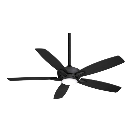
- Page 1 Model NO. F717L KELVYN...
- Page 2 ©2022 Minka Lighting Inc. Manual design and all elements of manual design are protected by United States Federal and/or State Law including Patents, Trademark, and/or Copyright Laws.
-
Page 3: Warranty Service Information
The Minka-Aire® warranty is for one (1) year from the date of purchase from an authorized Minka-Aire® dealer. This warranty is only valid to the original purchaser or user against all defects in material and workmanship (light bulbs excluded) for one (1) full year. Additionally, Minka-Aire® warrants the motor only for the lifetime of the Minka Aire ceiling fan (excluding wall controls and electrical components), to the original purchaser or user. - Page 4 INSTALLING THE CANOPY AND CANOPY COVER ATTACHING THE FAN BLADES ATTACHING THE BLADE ARMS INSTALLING THE 14W LED ASSEMBLY...
- Page 5 READ AND SAVE THESE INSTRUCTIONS. 1. To reduce the risk of electric shock, ensure electricity has been turned off at the circuit breaker or fuse box before beginning. 2. All wiring must be in accordance with the National Electrical Code “ANSI/NFPA 70- 1999”...
- Page 6 7. Fan motor assembly 8. Blade arm (5) B. Blade attachment hardware: 9. 14W CCT LED assembly 3/16” x 8mm blade screws ( 15 + 1 spare) 10. Receiver(1) + wire nut (6) Fiber washers ( 15 + 1 spare) 11.
- Page 7 Tools Required: Phillips screw driver; slotted screw driver; step-ladder; wire cutters; electrical tape. CEILING CROSS JOIST BRACE MOUNTING OPTIONS If there isn't an existing mounting box, then read OUTLET BOX the following instructions. Disconnect the power CEILING by removing fuses or turning off circuit breakers. JOIST Fig.
- Page 8 WARNING: All of the parts, hardware and components such as the hanger bracket and hanger ball have been provided for your safety and the proper installation of your new ceiling fan. The use of other parts, hardware or components not supplied ®...
- Page 9 Slip coupling cover, canopy cover Step 5. and canopy onto downrod. (Fig. CANOPY 9) Carefully reinstall hanger ball DOWNROD onto rod being sure that cross pin is in the correct position, set CANOPY screws are tighten and wires are COVER not twisted.
- Page 10 Fig. 11 Fig. 13 Fig. 12...
- Page 11 INSTALLING THE CANOPY AND CANOPY COVER (Fig. 14) (Fig. 14) OUTLET BOX HANGER BRACKET HANGER BALL CANOPY CANOPY COVER Fig. 14...
-
Page 12: Attaching The Fan Blades
ATTACHING THE FAN BLADES Attach the fan blade to the blade arm by using the three blade screws and the three fiber washers. Tighten all screws and washers securely. Repeat same process for the other four blades. (Fig.15) BLADE SCREW FIBER WASHER FAN BLADES BLADE ARM... - Page 13 ATTACHING THE BLADE ARMS Step 1. Tighten the blade assembly onto the bottom of fan motor assembly by using the two blade arm screws. Repeat same process for the other blade assemblies. (Fig.16) FAN MOTOR ASSEMBLY BLADE ARM BLADE ARM SCREW FAN BLADES FIG.
- Page 14 INSTALLING THE 14W LED ASSEMBLY CAUTION: To Reduce The Risk Of Electric Shock, Disconnect The Electrical Supply Circuit To The Fan Before Installing The Light Kit. Step 1. While holding the 14W LED assembly under your fan, firmly snap the wire connection plugs together.
- Page 15 Restore Power to Ceiling Fan. Note: This integrated light kit is capable of color changing light of 3000K , 3500K and 4000K. Buttons: These buttons are used to set the fan speeds as follows; = Low Speed = Medium Speed = High Speed FIG.
- Page 16 The reverse switch is located on the fan motor assembly (Fig.19). Slide the switch to the Left for warm weather operation. Slide the switch to the Right for cool weather operation. FIG. 19 FIG. 20 FIG. 21...
- Page 17 WARNING! MAKE SURE THE POWER IS OFF AT THE ELECTRICAL PANEL BOX BEFORE YOU ATTEMPT ANY REPAIRS. REFER TO THE SECTION, “ELECTRICAL CONNECTIONS”.
- Page 19 0.27 13.51 7.6 10.36 1.974' 0.59 70.35 165 3,258 1733 13.51 4603 70.35...
Need help?
Do you have a question about the minkaAire Contractor Series and is the answer not in the manual?
Questions and answers