Table of Contents
Advertisement
Quick Links
Advertisement
Table of Contents

Related Manuals for Daikin RXL35G3V1


Summary of Contents for Daikin RXL35G3V1
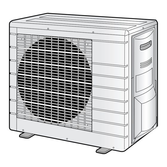
- Page 1 OUTDOOR UNIT R410A Split Series INSTALLATION MANUAL Installation manual Installationsmanual Installationshandbok Installasjonshåndbok Asennusohje Installierungshandbuch Manuel d’installation óêîâîäñòâî ïî ìîíòàæó Instrukcja montazu Installatiehandleiding MODEL RXL35G3V1B...
- Page 2 3SB64417-12H...
-
Page 3: Safety Precautions
Safety Precautions • The precautions described herein are classified as WARNING and CAUTION. They both contain important information regarding safety. Be sure to observe all precautions without fail. • Meaning of WARNING and CAUTION notices WARNING ..Failure to follow these instructions properly may result in personal injury or loss of life. CAUTION .. -
Page 4: Precautions For Selecting The Location
Accessories Accessories supplied with the outdoor unit: (B) Refrigerant charge label (A) Installation Manual Precautions for Selecting the Location 1) Choose a place solid enough to bear the weight and vibration of the unit, where the operation noise will not be amplified. 2) Choose a location where the hot air discharged from the unit or the operation noise will not cause a nuisance to the neighbors of the user. -
Page 5: Outdoor Unit Installation Drawings
Outdoor Unit Installation Drawings Max. allowable length Min. allowable length 1.5m Max. allowable height Additional refrigerant required for refrigerant 20g/m pipe exceeding 10m in length. Gas pipe O.D. 12.7mm Wrap the insulation pipe with the finishing Liquid pipe O.D. 6.4mm tape from bottom to top. -
Page 6: Precautions On Installation
Installation Guidelines • Where a wall or other obstacle is in the path of outdoor unit’s intake or exhaust airflow, follow the installation guidelines below. • For any of the below installation patterns, the wall height on the exhaust side should be 1200mm or less. Wall facing one side Walls facing two sides More than 100... -
Page 7: Outdoor Unit Installation
Outdoor Unit Installation Flaring the pipe end. (Cut exactly at 1) Cut the pipe end with a pipe cutter. right angles.) Remove burrs 2) Remove burrs with the cut surface facing down- Flaring ward so that the chips do not enter the pipe. Set exactly at the position shown below. -
Page 8: Purging Air And Checking Gas Leakage
Purging air and checking gas leakage. • When piping work is completed, it is necessary to purge the air and check for gas leakage. WARNING 1) Do not mix any substance other than the specified refrigerant (R410A) into the refrigeration cycle. 2) When refrigerant gas leaks occur, ventilate the room as soon and as much as possible. -
Page 9: Refrigerant Piping Work
Outdoor Unit Installation Refilling the refrigerant. Check the type of refrigerant to be used on the machine nameplate. Precautions when adding R410A Fill from the liquid pipe in liquid form. It is a mixed refrigerant, so adding it in gas form may cause the refrigerant composition to change, preventing normal operation. 1) Before filling, check whether the cylinder has a siphon attached or not. -
Page 10: Pump Down Operation
Pump Down Operation In order to protect the environment, be sure to pump down when relocating or disposing of the unit. 1) Remove the valve cap from liquid stop valve and gas stop valve. Hexagonal wrench 2) Carry out forced cooling operation. 3) After five to ten minutes, close the liquid stop valve with a Close hexagonal wrench. - Page 11 Wiring WARNING 1) Do not use tapped wires, stranded wires, extension cords, or starburst connections, as they may cause overheating, electrical shock, or fire. 2) Do not use locally purchased electrical parts inside the product. (Do not branch the power for the drain pump, etc., from the terminal block.) Doing so may cause electric shock or fire.
- Page 12 Observe the notes mentioned following when wiring to the power supply terminal board. Round crimp-style Precautions to be taken for power supply wiring. terminal Use a round crimp-style terminal for connection to the power supply terminal Stranded Wire board. In case it cannot be used due to unavoidable reasons, be sure to observe the following instruction.
-
Page 13: Test Run And Final Check
Test Run and Final Check Trial operation and testing. 1-1 Measure the supply voltage and make sure that it falls in the specified range. 1-2 Trial operation should be carried out in either cooling or heating mode. • In cooling mode, select the lowest programmable temperature; in heating mode, select the highest programmable temper- ature. - Page 14 Two-dimensional bar code is a code for manufacturing. 3P232550-13C M10B238 (1010) HT...
Need help?
Do you have a question about the RXL35G3V1 and is the answer not in the manual?
Questions and answers