
Related Manuals for Daikin RX09WMVJU9


Summary of Contents for Daikin RX09WMVJU9
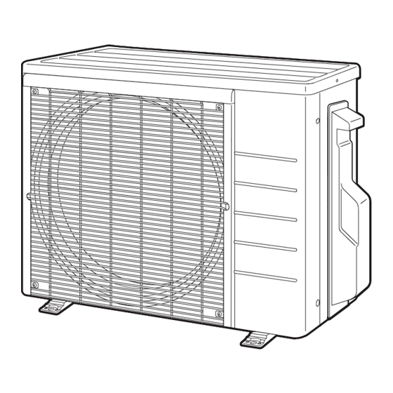
- Page 1 DAIKIN ROOM AIR CONDITIONER INSTALLATION MANUAL R410A Split Series Installation manual Manuel d’installation Manual de instalación MODELS RX09WMVJU9 RX12WMVJU9 RXL09WMVJU9 RXL12WMVJU9...
-
Page 2: Table Of Contents
Contents 4. Refrigerant piping ............6 Safety Considerations ........1 5. Pressure test and evacuating system ......7 Accessories ............. 3 6. Refilling refrigerant ............8 Precautions for Selecting a Location ... 3 Wiring ............... 9 Precautions on Installation ......4 Facility Setting (cooling at low outdoor temperature) ... - Page 3 (a) Where a mineral oil mist or oil spray or vapor is specified by Daikin are used, fire or explosion may occur. produced, for example, in a kitchen. Plastic parts may deteriorate and fall off or result in •...
-
Page 4: Accessories
Accessories Drain socket Installation manual This is at the bottom of the packaging. Drain cap (1) Drain cap (2) Warranty General safety consideration Precautions for Selecting a Location 1) Choose a place solid enough to bear the weight and vibration of the unit, where the operating sound will not be amplified. 2) Choose a location where the air discharged from the unit or the operating sound will not cause a nuisance to the neighbors of the user. -
Page 5: Precautions On Installation
Precautions on Installation • Check the strength and level of the installation surface so that the unit does not cause any operating vibrations or noise after installation. • Fix the unit in place securely using foundation bolts, as in the figure. (Prepare 4 sets of 5/16 inch (M8) or 3/8 inch (M10) foundation bolts, nuts and washers; all sold separately.) •... -
Page 6: Installation Space Requirements
Installation Space Requirements • Position the unit on a horizontal surface. Any tilt in the unit should be 3° or less to the horizontal. • Where a wall or other obstacle is in the path of the outdoor unit’s intake or exhaust airflow, follow the installation space requirements below. • For any of the below installation patterns, the wall height on the outlet side should be 47-1/4 inch (1200mm) or less. •... -
Page 7: Flaring The Pipe End
Flaring the pipe end WARNING • Do not apply mineral oil to the flare. • Prevent mineral oil from getting into the system as this would reduce the service life of the units. • Never use piping which has been used for previous installations. Only use parts which are delivered with this unit. •... -
Page 8: Pressure Test And Evacuating System
Outdoor Unit Installation Cautions on pipe handling Wall Be sure to • Protect the open end of the pipe from dust and moisture. place a cap. • All pipe bends should be as gentle as possible. Use a pipe bender for bending. Rain If no flare cap is available, cover... -
Page 9: Refilling Refrigerant
• When piping work is complete, it is necessary to perform a pressure test Compound Pressure High-pressure pressure gauge meter valve and evacuate system with a vacuum pump. • If using additional refrigerant, purge the air from the refrigerant pipes and indoor unit using a vacuum pump, then charge additional refrigerant. -
Page 10: Wiring
Wiring WARNING • Do not ground units to water pipes, gas pipes, telephone wires, or lightning rods as incomplete grounding can cause a severe shock hazard resulting in severe injury or death. Additionally, grounding to gas pipes could cause a gas leak and potential explosion causing severe injury or death. • Do not use tapped wires, extension cords, or starburst connections, as they may cause overheating, electric shock, or fire. • Do not use locally purchased electrical parts inside the product. (Do not branch the power for the drain pump, etc., from the terminal block.) Doing so may cause electric shock or fire. -
Page 11: Facility Setting (Cooling At Low Outdoor Temperature)
[Method of mounting conduit] • A protection plate is fixed for protection from the high-voltage section. 1) Dismount the stop valve cover by removing the screw. 2) Dismount the protection plate by removing the 2 screws. 3) Dismount the conduit mounting cover by removing the 2 screws. 4) Pass wires through the conduit and secure them with a lock nut. 5) After completing the work, reattach the conduit mounting cover, the protection plate, and the stop valve cover to its original position. -
Page 12: When Attaching The Drain Pan Heater
Facility Setting (cooling at low outdoor temperature) This function is designed for facilities such as equipment or computer rooms. It is never to be used in a residence or office where people occupy the space. „ Cutting the jumper 6 (J6) on the circuit board will expand the operation range down to 14°F (–10°C). Installing an air direction adjustment grille (sold separately) will further extend the operation range to –4°F (–20°C). -
Page 13: Pump Down Operation
Pump Down Operation In order to protect the environment, be sure to pump down when relocating or disposing of the unit. 1) Remove the valve caps from the liquid stop valve and gas stop valve. 2) Begin forced cooling operation. 3) After 5 to 10 minutes, close the liquid stop valve with a hexagonal wrench. -
Page 14: Trial Operation And Testing
Pump Down Operation [For wireless remote controller] 1) Press and select the COOL operation. 2) Press twice. “Test” is displayed. 3) Press within 10 seconds, and the forced cooling operation starts. • Forced cooling operation will stop automatically after about 15 minutes. To stop the operation, press Trial Operation and Testing Trial operation and testing... - Page 15 MEMO ■ English...
- Page 16 Two-dimensional bar code is a manufacturing code. 3P686855-1 M21B526 (2205) HT...
Need help?
Do you have a question about the RX09WMVJU9 and is the answer not in the manual?
Questions and answers