Powermatic DDS-225 Operating Instructions And Parts Manual
Dual drum sander
Hide thumbs
Also See for DDS-225:
- Operating instructions and parts manual (44 pages) ,
- Operating instructions and parts manual (88 pages)
Table of Contents
Advertisement
Quick Links
Advertisement
Table of Contents

Related Manuals for Powermatic DDS-225


Summary of Contents for Powermatic DDS-225
- Page 1 Operating Instructions and Parts Manual Dual Drum Sander Models DDS-225 and DDS-237 JPW Industries, Inc. 427 New Sanford Road LaVergne, Tennessee 37086 Part No. M-0460278 Ph.: 800-274-6848 Revision A 04/2019 Copyright © 2014 Powermatic www.powermatic.com...
-
Page 2: Table Of Contents
Parts – DDS-225 Sander ..........................22 Drum Assembly – DDS-225 ........................22 Conveyor Assembly – DDS-225 ......................24 Motor & Cabinet Assembly – DDS-225 ....................26 Gearbox Assembly – DDS-225 ....................... 29 DDS-225 DRO Assembly ........................31 Parts – DDS-237 Sander ..........................32 Drum Assembly –... - Page 3 When normal safety precautions are overlooked or ignored, personal injury to the operator can result. 6. Do not use this drum sander for other than its intended use. If used for other purposes, Powermatic disclaims any real or implied warranty and holds itself harmless from any injury that may result from that use.
- Page 4 22. USE THE RIGHT TOOL at the correct speed and feed rate. DO NOT FORCE A TOOL or attachment to do a job for which it was not designed. The right tool will do the job better and safer. 23. USE RECOMMENDED ACCESSORIES; improper accessories may be hazardous. 24.
-
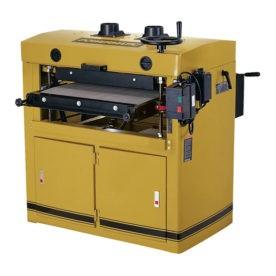
Page 5: Features
Features Figure 1 Figure 2 – Dust Port Locations... -
Page 6: Specifications
Electrical Controls (all models)............... 400V magnetic w/ reversing switch The specifications in this manual are given as general information and are not binding. Powermatic reserves the right to effect, at any time and without prior notice, changes or alterations to parts, fittings,... -
Page 7: Shipping Contents
Shipping Contents Note 1: Some parts are inside a box in the cabinet. Note 2: Models DDS-225 and DDS-237 Drum Sanders come from the factory with the first set of abrasive strips installed with 80 grit sandpaper on the front drum and 100 grit on the rear drum. -
Page 8: Assembly
Exposed metal surfaces, such as the shafts on the drums and pressure rollers, have been given a protective coating at the factory. This should be removed with a soft cloth moistened with kerosene. Do not use acetone, gasoline, or lacquer thinner for this purpose. - Page 9 Note: If the wedge sticks, use a flat head screwdriver as leverage to free it. 3. Cut a length of the Ready-To-Cut abrasive strip (14'-9" for the DDS-225, 21'-3" for the DDS-237). This will be enough to cover one drum.
-
Page 10: Drum Height
clockwise spiral fashion by rotating the drum with your left hand and guiding the strip with your right hand (Fig. 11). Successive windings of the strip should be flush with previous windings without any overlap. 7. The left end of the drum which contains the recess is an independent piece (Fig. -
Page 11: Pressure Rollers
Pressure Rollers The pressure rollers (Fig. 15) maintain tension upon the workpiece as it passes through the machine. The spring tension of the pressure rollers has been factory set. If a board refuses to pass through the machine, or the finished surface of a board is uneven, the spring tension of the pressure rollers may need adjusting. -
Page 12: Lead Screw Thread Clearance
4. Insert a tool, such as a hex wrench or screwdriver, through the hole on top of the leadscrew (Fig 18) at that corner of the table that is lowest. 5. Turn the leadscrew clockwise to raise the table. 6. When the adjustment is complete, install the chain over the four sprockets, and over the chain tensioner roller. -
Page 13: Conveyor Belt
Conveyor Belt Conveyor belt tension and tracking adjustments may occasionally be necessary during break-in and normal operation to compensate for belt stretching. Adjust the tension of the conveyor belt by turning the knobs (Fig. 20) clockwise to increase tension, counterclockwise to decrease tension. -
Page 14: Pulley Alignment
Pulley Alignment The drum and motor pulleys must be in line so that the belts are straight. To check this: Place a straight edge, such as a metal ruler, against the flat sides of the motor pulley and a drum pulley (Fig. 23). If the straight edge does not lie flush on the flat sides of the pulleys, loosen the set screw on the motor pulley (Fig. -
Page 15: Maintenance
type of wood, and feed rate. For best results, Maintenance use scrap wood to practice sanding and to develop skill and familiarity with the machine Note: See also Maintenance Checklist on before doing finish work. page 19. A good rule of thumb when sanding with grits For best results, perform the following proced- finer than 80 is to lower the drum so it contacts ures on a routine basis:... -
Page 16: Edge Sanding
Ready-To-Cut strips are available If possible, support such stock as it is being from Powermatic and are listed on page 39. sanded to keep it from slipping or tipping. Use extra roller stands, help from another person, or... -
Page 17: Switch Lock
Cloth backed abrasives may also be cleaned by from the drum and reversing it. To do this, soaking in paint thinner or mineral spirits for 20 remove the strip and use what was the trailing minutes to 1 hour, then using a brush to remove end as the starting end on the right side of the any build-up or burns. -
Page 18: Functions Of Digital Scale
While in absolute mode, press ON/OFF/ZERO (no Functions of digital scale longer than 3 seconds) to set current position as absolute zero point. Figure 6 identifies the parts of the digital scale. The – relative/absolute modes button functions are discussed below, followed by a section giving practical examples of how to The device is in absolute mode as soon as power calibrate your settings, and how these functions... -
Page 19: Calibration And Operation
Adjust the drum back to its original (frozen The absolute setting, for which you should have display) position. already established the zero point, gives the width of your finished board after sanding (distance from NOTE: The HOLD button will not permanently save drum to table). -
Page 20: Maintenance Checklist
Maintenance Checklist Lubricate chain and check tension. Note: See also the Maintenance section on Check belt condition - replace as needed. page 16. Dress with paraffin. Check belt tension. Work area around machine marked off Check motor for loose wiring and sawdust clearly. -
Page 21: Mechanical & Electrical Problems
Mechanical & Electrical Problems Problem: Machine will not start, restart, or repeatedly trips circuit breaker or blows fuses Possible Cause Solution 1. No incoming power 1. Verify unit is connected to power. 2. Overload automatic reset 2. When sander overloads on the circuit breaker built into the motor has not reset starter, it takes time for the machine to cool down before restart. -
Page 22: Parts - Dds-225 Sander
Parts – DDS-225 Sander Drum Assembly – DDS-225 Index No. Part No. Description Size 1 ....DDS225-101A ..Rear Drum....................1 2 ....DDS225-102A ..Abrasive Fastener-Right ................2 3 ....DDS225-103A ..Abrasive Fastener-Left ................2 4 .... - Page 23 Drum Assembly – DDS-225 Index No. Part No. Description Size 55 ..... TS-1521021 ..... Socket Set Screw ..........M4 x 6 ......4 56 ..... DDS225-156 .... Roll Pin ..............2 x 8mm ....2 ....DDS225-LSBA ..Left Slide Bracket Assembly ..............1 (index # 31-37 ,39, 41-43, 45-46, 48,52,53, 55,56) ....
-
Page 24: Conveyor Assembly - Dds-225
Conveyor Assembly – DDS-225 Index No. Part No. Description Size 1 ....DDS225-201 .... Table ......................1 2 ....DDS225-202 .... Support Bracket, Left-Front ..............1 3 ....DDS225-203 .... Support Bracket, Right-Front ..............1 4 ....DDS225-204 .... Support Bracket, Left-Rear ..............1 5 .... - Page 25 Conveyor Assembly – DDS-225 Index No. Part No. Description Size 56 ..... TS-081C022 ..... Screw ..............#10-24 x 3/8 ....8 57 ..... DDS237-260 .... Boot ......................4 59 ..... TS-0208021 ..... Socket Head Cap Screw ........5/16-18 x 1/2 ....8 60 .....
-
Page 26: Motor & Cabinet Assembly - Dds-225
Motor & Cabinet Assembly – DDS-225 Index No. Part No. Description Size 1 ....DDS225-301 .... Cabinet ..................... 1 2 ....DDS225-302 .... Support Bracket-Front ................1 3 ....DDS225-303 .... Support Bracket-Rear ................1 4 ....DDS225-304 .... Motor Plate ....................1 5 .... - Page 27 82 ..... DDS225-382 .... Reverse Switch ..................1 83 ..... DDS225-383 .... Switch Bracket ..................1 85 ..... 3312341 ....Powermatic Logo ..................1 86 ..... DDS225-WL ..... Warning Label (not shown) ..............1 87 ..... DDS225-387 .... Grounding Cord ..................1 88 .....
- Page 28 Motor & Cabinet Assembly – DDS-225...
-
Page 29: Gearbox Assembly - Dds-225
Gearbox Assembly – DDS-225 Index No. Part No. Description Size ....DDS225-GBA ... Complete Gearbox Assembly w/Motor ....400V......1 ....DDS225-401CGA ..Complete Gearbox Assembly wo/Motor ..........1 1 ....DDS225-401A ..Gearbox Body ..................1 2 ....TS-0720071 ..... Lock Washer ............1/4 ....... 4 3 .... - Page 30 Gearbox Assembly – DDS-225 Drum...
-
Page 31: Dds-225 Dro Assembly
DDS-225 DRO Assembly Index No. Part No. Description Size ....DDS225-DROA ..Digital Readout Assembly (Includes index #1 ~ #10) ....... 1 1 ....TS-0680011 ..... Flat Washer ............3/16 ......4 2 ....DDS225-502 .... Screw ..............3/16-24x5/16 ....4 3 .... -
Page 32: Parts - Dds-237 Sander
Parts – DDS-237 Sander Drum Assembly – DDS-237 Index No. Part No. Description Size 1 ....DDS237-101B ..Rear Drum....................1 2 ....DDS225-102A ..Abrasive Fastener-Right ................2 3 ....DDS225-103A ..Abrasive Fastener-Left ................2 4 .... - Page 33 Drum Assembly – DDS-237 Index No. Part No. Description Size 54 ..... DDS237-154B ..Front Drum ( ) ........1 serial no. 1008DDS2370150 and higher 55 ..... TS-1521041 ..... Socket Set Screw ..........M4 x 10 ....... 4 56 ..... DDS225-156 .... Roll Pin ..............2 x 8mm ....2 57 .....
-
Page 34: Conveyor Assembly - Dds-237
Conveyor Assembly – DDS-237 Index No. Part No. Description Size 1 ....DDS237-201 .... Table ......................1 2 ....DDS225-202 .... Support Bracket, Left-Front ..............1 3 ....DDS225-203 .... Support Bracket, Right-Front ..............1 4 ....DDS225-204 .... Support Bracket, Left-Rear ..............1 5 .... - Page 35 Conveyor Assembly – DDS-237 Index No. Part No. Description Size 59 ..... DDS237-259 .... Upper Bracket ..................4 60 ..... DDS237-260 .... Boot ......................4 61 ..... TS-081C022 ..... Screw ..............#10-24 x 3/8 ....8 62 ..... TS-0680021 ..... Flat Washer ............1/4 ....... 8 63 .....
-
Page 36: Motor And Cabinet Assembly - Dds-237
Motor and Cabinet Assembly – DDS-237 Index No. Part No. Description Size 1 ....DDS237-301 .... Cabinet ..................... 1 2 ....DDS237-302 .... Support Bracket-Front ................1 3 ....DDS237-303 .... Support Bracket-Rear ................1 4 ....DDS237-304 .... Motor Plate ....................1 5 .... - Page 37 83 ..... DDS225-383 .... Switch Bracket ..................1 84 ..... DDS225-384RU ..Strain Relief....................3 85 ..... DDS237-385 .... Powermatic Logo ..................1 86 ..... DDS237-386 .... I.D. Label (not shown) ................1 87 ..... TS-2361101 ..... Lock Washer ............M10 ......1 88 .....
- Page 38 Motor and Cabinet Assembly – DDS-237...
-
Page 39: Gearbox Assembly - Dds-237
Gearbox Assembly – DDS-237 ....DDS225-GBA ... Complete Gearbox Assembly w/Motor ....400V......1 ....DDS225-401CGA ..Complete Gearbox Assembly wo/Motor ..........1 1 ....DDS225-401A ..Gearbox Body ..................1 2 ....TS-0720071 ..... Lock Washer ............1/4 ....... 4 3 .... - Page 40 Gearbox Assembly – DDS-237...
-
Page 41: Dds-237 Dro Assembly
DDS-237 DRO Assembly Index No. Part No. Description Size ....DDS225-DROA ..Digital Readout Assembly (Includes index #1 ~ #10) ....... 1 1 ....TS-0680011 ..... Flat Washer ............3/16 ......4 2 ....DDS225-502 .... Screw ..............3/16-24x5/16 ....4 3 .... - Page 42 Wiring Diagrams DDS-225 Sander - 5HP, 3Ph, 400V...
- Page 43 DDS-237 Sander – 10HP, 3Ph, 400V...
- Page 44 427 New Sanford Road LaVergne, Tennessee 37086 Phone: 800-274-6848 www.powermatic.com...
Need help?
Do you have a question about the DDS-225 and is the answer not in the manual?
Questions and answers