Table of Contents
Advertisement
Quick Links
Advertisement
Table of Contents

Related Manuals for Powermatic 1632


Summary of Contents for Powermatic 1632
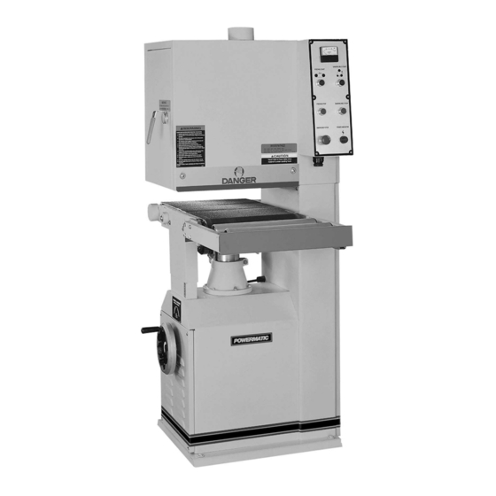
- Page 1 This .pdf document is bookmarked Operating Instructions and Parts Manual 16-inch Open-End Belt Sander Model 1632 Powermatic 427 New Sanford Road LaVergne, Tennessee 37086 Part No. M-0460219 Ph.: 800-274-6848 Revision H2 01/2017 www.powermatic.com Copyright © 2017 Powermatic...
-
Page 2: Warranty And Service
1.0 Warranty and Service Powermatic warrants every product it sells against manufacturers’ defects. If one of our tools needs service or repair, please contact Technical Service by calling 1-800-274-6846, 8AM to 5PM CST, Monday through Friday. Warranty Period The general warranty lasts for the time period specified in the literature included with your product or on the official Powermatic branded website. -
Page 3: Table Of Contents
12.5.2 Reduction Motor – Exploded View ...................... 22 12.5.3 Conveyor Belt and Table; Reduction Motor – Parts List ..............23 13.0 Electrical Connections – 1632 Sander ....................... 25 13.1 460V – 3 Phase ............................25 13.2 230V – 1 Phase / 3 Phase ........................26... -
Page 4: Safety Warnings
Know the limitations and hazards associated Powermatic recommends the use of anti-skid with this machine. floor strips on the floor area where the Electrical grounding. Make certain that the operator normally stands and that each machine’s work area be marked off. -
Page 5: About This Manual
If there are questions or comments, please contact your local supplier or Powermatic. Powermatic can also be reached at our web site: www.powermatic.com. -
Page 6: Specifications
Shipping weight ............1,106 lbs............1,106 lbs. The specifications in this manual were current at time of publication, but because of our policy of continuous improvement, Powermatic reserves the right to change specifications at any time and without prior notice, without incurring obligations. -
Page 7: Setup And Assembly
Remove the wiring cover and attach the 6.0 Setup and assembly ground wire (A), Figure 1. Remove the sander from its crate and inspect for For 3 Phase: Connect the three power leads damage to ensure all parts are intact. Any damage (B) to the wiring board. -
Page 8: Adjustments
An undersized cord will cause a drop in line voltage resulting in loss of power and overheating. Table 1 shows correct size to use depending on cord length and nameplate ampere rating. If in doubt, use the next heavier gauge. The smaller the gauge number, the heavier the cord. -
Page 9: Feed Speed Adjustment
Sanding Belt Stop (F) will stop the sanding belt 8.5 Feed speed adjustment only. The Model 1632 has two speeds that feed the workpiece at 15 feet per minute (FPM) finished surface sanding, and 32.5 FPM for faster, lighter sanding. -
Page 10: Maintenance
9. Refer to the scale for the desired setting. The recommended depth of sanding is .0164" or two revolutions of the handwheel. The table can be locked in place by the lever at the base of the column. Turn on the power to the machine. Start the sanding belt. -
Page 11: Troubleshooting The 1632 Sander
11.0 Troubleshooting the 1632 Sander Symptom Possible Cause Correction Motor will not start Low voltage. Check power line for proper voltage. Open circuit motor loose Inspect all lead connections on motor for connection. loose or open connections. Motor will not start: fuses Short circuit in line cord or plug. -
Page 12: Air Control Assembly - Exploded View
12.1.1 Air Control Assembly – Exploded View 12.1.2 Air Control Assembly – Parts List Index No Part No Description Size 1 ....6293482 ....Filter ....................... 1 2 ....6293483 ....Solenoid Valve ....................1 3 ....6293484 ....Brake Cylinder ....................1 4 .... -
Page 13: Electrical Control And Upper Adjustment Roller - Exploded View
12.2.1 Electrical Control and Upper Adjustment Roller – Exploded View... -
Page 14: Electrical Control And Upper Adjustment Roller - Parts List
32 ....6293234 ....Terminal Strip (5 HP) ..................1 ....6293313 ....Terminal Strip (7-1/2 HP) ................1 33 ....1632-233 ....Relay (5 HP) ....................1 ....6293314 ....Relay (7-1/2 HP) .................... 1 34 .... -
Page 15: Sanding Drum Assembly - Exploded View
12.3.1 Sanding Drum Assembly – Exploded View... -
Page 16: Sanding Drum Assembly - Parts List
12.3.2 Sanding Drum Assembly – Parts List Index No Part No Description Size 1 ....6293240 ....Ring ....................... 2 2 ....6293241 ....Ball Bearing ....................2 3 ....6293242 ....Shaft ......................1 4 ....6293243 ....Upper Roller....................1 5 .... - Page 17 Index No Part No Description Size 57 ....6293296 ....Graphite Canvas .................... 1 58 ....6293297 ....Pulley (5 HP)....................1 ....6293298 ....Pulley (7-1/2 HP) ................... 1 59 ....6293299 ....Flat Washer ............. 5/16” ......1 60 ....
-
Page 18: Base And Table Adjustment Assembly - Parts List
12.4.1 Base and Table Adjustment Assembly – Parts List... -
Page 19: Base And Table Adjustment Assembly - Parts List
19 ....6293433 ....Socket Head Screw ..........5/16” x 1/2" ....6 20 ....6293434 ....Bolt................3/8” x 1-1/2” ....1 21 ....1632-421 ....Pulley (5 HP)....................1 ....6293436 ....Pulley (7-1/2 HP) ................... 1 22 .... - Page 20 Index No Part No Description Size 57 ....6293450 ....Hex Nut ..............1/4" ........ 1 58 ....6293465 ....Wheel............... 8" ........1 59 ....6293466 ....Handle ......................1 60 ....6293209 ....Pan Head Screw ............1/4" x 1/2"...... 2 61 ....
-
Page 21: Conveyor Belt And Table - Exploded View
12.5.1 Conveyor Belt and Table – Exploded View... -
Page 22: Reduction Motor - Exploded View
12.5.2 Reduction Motor – Exploded View... -
Page 23: Conveyor Belt And Table; Reduction Motor - Parts List
12.5.3 Conveyor Belt and Table; Reduction Motor – Parts List Index No Part No Description Size 1 ....6293351 ....Hex Socket Cap Screw ..........1/4" x 1/4"...... 6 2 ....6293352 ....Bearing Cover ....................2 3 ....6293353 ....Ball Bearing ....................2 4 .... - Page 24 Index No Part No Description Size 58 ....6293395 ....Stop Plate Annex ................... 2 59 ....6293396 ....PVC Roller ..................... 2 60 ....6293397 ....Hex Head Screw ............5/16” X 1-1/2” ....2 61 ....6293398 ....Ring ....................... 2 62 ....
-
Page 25: Electrical Connections - 1632 Sander
13.0 Electrical Connections – 1632 Sander 13.1 460V – 3 Phase... -
Page 26: 230V - 1 Phase / 3 Phase
13.2 230V – 1 Phase / 3 Phase... - Page 27 This page intentionally left blank.
- Page 28 This page intentionally left blank. 427 New Sanford Road LaVergne, Tennessee 37086 Phone: 800-274-6848 www.powermatic.com...
Need help?
Do you have a question about the 1632 and is the answer not in the manual?
Questions and answers