
Subscribe to Our Youtube Channel
Related Manuals for Power Innovations EVQC030-35


Summary of Contents for Power Innovations EVQC030-35
- Page 1 EV Quick Charger – DC 30 kW Model EVQC030-35 Installation and Operation Manual MNL212 Revision 1.0...
- Page 2 This manual may accompany other instructional guides or manuals for standard installation and operations of the supported products. Please contact Power Innovations if you need additional guides or manuals and have not received them. Product names mentioned herein may be trademarks (™) and/or registered trademarks (®) of their respective companies, which may include Power Innovations International, Inc.
-
Page 3: Table Of Contents
Acronyms Used in this Manual ..........................3 2— Safety and Specifications .............................. 4 IMPORTANT SAFETY INSTRUCTIONS – SAVE THESE INSTRUCTIONS ............4 Specifications - EV Quick Charger Model EVQC030-35 ..................5 3— Installing EV Charger ..............................6 What’s Provided with Charger ..........................6 Mounting Options (sold separately) .......................... - Page 4 This page left blank intentionally. iv | MNL212 Revision 1.0 7/7/2023...
-
Page 5: 1-Product Overview
1—Product Overview This section provides product overview for EVQC030-35, Power Innovations DC 30 kW Quick Charger. Introduction This quick charger is an all-in-one electric vehicle (EV) power supply and charging authorization terminal. Once installed and operational, an operator can plug the EV charging cable into their electric vehicle, use an RFID payment card to tap on, be authorized by the system, and start a charging session. -
Page 6: Charger Features Identified
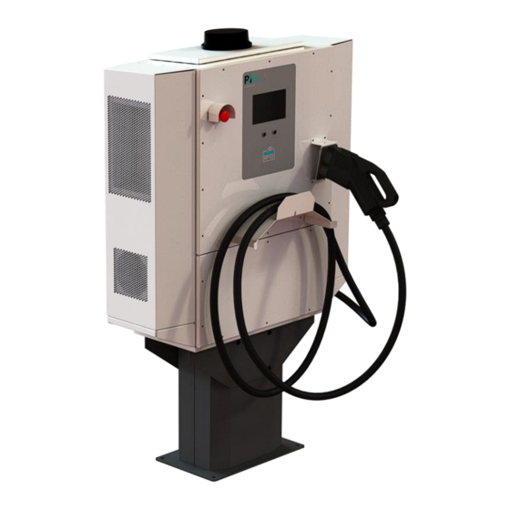
Cooling Fans Emergency Stop Button User Interface LCD Screen ACCEPT Button Cooling Fans Plug Holster CANCEL Button CCS1 Charging Cable Cable Hanger RFID Card Reader Handhold AC Service Panel Handhold Figure 1—EV Quick Charger Model EVQC030-35 MNL 212 Revision 1.0 7/7/2023... -
Page 7: Symbols Used In This Manual
Symbols Used in this Manual Icons or symbols are occasionally used throughout this manual to help identify safety warnings and other pertinent content contained here. These icons are described in the table below. Icon Type of Warning Description WARNING! RISK OF ELECTRIC SHOCK! ELECTRICAL WARNING! ADDITIONAL TEXT THAT FOLLOWS THIS SYMBOL PROVIDES MORE INFORMATION ABOUT THE... -
Page 8: 2-Safety And Specifications
2—Safety and Specifications The following safety instructions apply throughout the EV Charger installation process. Be familiar with them before moving on to the next section to complete the installation. IMPORTANT SAFETY INSTRUCTIONS – SAVE THESE INSTRUCTIONS ELECTRICAL WARNINGS – WARNING! RISK OF ELECTRIC SHOCK! WARNING! RISK OF ELECTRIC SHOCK! ONLY QUALIFIED ELECTRICAL PERSONNEL FAMILIAR WITH THE CONSTUCTION AND OPERATION OF THIS TYPE OF EQUIPMENT AND THE HAZARDS INVOLVED SHOULD... -
Page 9: Specifications - Ev Quick Charger Model Evqc030-35
Specifications - EV Quick Charger Model EVQC030-35 Electrical Specifications AC Input AC Input Power Options 240V single phase 208V/240V 3-phase, 4-wire Delta 480V 3-phase, 5-wire Wye AC Input Voltage Operating Range and 240V single phase: 190V to 305V, 150A max... -
Page 10: 3-Installing Ev Charger
3 Bus Bars, each uniquely configured 6 Socket Head Cap Screws, M6 x 14 mm long 4 Socket Head Cap Screws, M8 x 16 mm long “EV Quick Charger – DC 30 kW Model EVQC030-35, Installation and Operation MNL212 Manual” (this document) -
Page 11: Prepare Installation Site
Prepare Installation Site 1. Become familiar with essential dimensions of EV Quick Charger and Pedestal Model Model EVQC030-35 EVQC030-PEDP as shown in Figures 2.1, 2.2, 2.3, and 2.4. Figure 2.2— Width of 30kW Charger Figure 2.1—Height of 30kW Charger and Pedestal Figure 2.3—Dimensions of Pedestal Baseplate... - Page 12 2. Best practices for both wall-mounted and pedestal- mounted chargers installation locations: (a) Select location where charger will not be in direct sunlight. (b) When laying out placement, ensure minimum space between chargers will be 914 mm (36 in.) to help ensure good air flow and user accessibility around charger (Figure 3).
-
Page 13: Mount (A) Wall-Mount Bracket Or (B) Pedestal
Mount (A) Wall-mount Bracket or (B) Pedestal Note: When mounting charger on wall or pedestal, be sure to follow mounting height and spacing recommendations provided in this manual to comply with the guidelines outlined in the American Disability Act (ADA). 3.5 A - Mount Wall-mount Bracket on Wall 3.5 B - Mount Pedestal on Concrete Note: Uninstalled charger weighs 260 lbs. -
Page 14: Attach Charger To (A) Wall-Mount Bracket Or (B) Pedestal
Attach Charger to (A) Wall-mount Bracket or (B) Pedestal ELECTRICAL WARNINGS – WARNING! RISK OF ELECTRIC SHOCK! WARNING! RISK OF ELECTRIC SHOCK! SHUT OFF POWER SUPPLY BEFORE BEGINNING INSTALLATION ACTIVITIES AND BEFORE REMOVING EV QUICK CHARGER’S AC SERVICE PANEL FOR ANY INSTALLATION ACTIVITY. FAILURE TO OBSERVE THIS PRECAUTION COULD RESULT IN SEVERE INJURY OR DEATH. -
Page 15: Install Power Supply Units And Shelf Controllers
Install Power Supply Units and Shelf Controllers ELECTRICAL WARNINGS – WARNING! RISK OF ELECTRIC SHOCK! WARNING! RISK OF ELECTRIC SHOCK! ENSURE POWER SUPPLY IS SHUT OFF BEFORE STARTING OR CONTINUING INSTALLATION ACTIVITIES AND BEFORE OPENING EV QUICK CHARGER’S TOP PANEL. FAILURE TO OBSERVE THIS PRECAUTION COULD RESULT IN SEVERE INJURY OR DEATH. - Page 16 Insert 3 Shelf Controllers (SCs), 1 on each shelf (Figure 17.1) and secure with built-in screw (Figure 17.2). Figure 17.1—Install Shelf Controllers Figure 17.2—Secure Shelf Controller 4. Insert 9 power supply units (PSUs), 3 on each shelf (Figure 18) 5. (Optional) To configure cellular modem now, leave top panel open and skip to next section. 6.
-
Page 17: Configure Cellular Modem And Registering Charger On Network
Configure Cellular Modem and Registering Charger on Network WARNING! RISK OF ELECTRIC SHOCK! DO NOT CONNECT POWER SUPPLY TO EV QUICK CHARGER UNTIL SIM CARDS ARE INSERTED INTO CELLULAR MODEM AND TOP PANEL COVER AND SCREWS ARE REINSTATED. Note: SIM cards for cellular modem must be provided by product owner or administrator. To configure cellular modem and register charger on the backend network: 1. -
Page 18: Configure And Wire Ac Input Power
Configure and Wire AC Input Power ELECTRICAL WARNINGS – WARNING! RISK OF ELECTRIC SHOCK! WARNING! RISK OF ELECTRIC SHOCK! SHUT OFF POWER SUPPLY BEFORE BEGINNING INSTALLATION ACTIVITIES. FAILURE TO OBSERVE THIS PRECAUTION COULD RESULT IN SEVERE INJURY OR DEATH. WARNING! RISK OF ELECTRIC SHOCK! DO NOT PROVIDE LIVE POWER TO THE EV QUICK CHARGER UNTIL BUS BAR CONFIGURATION AND AC WIRING IS COMPLETE AND THE AC SERVICE PANEL IS IN PLACE AND SECURE. - Page 19 3. Determine which of the three supported configurations is required for this installation. 240V (single phase): Line, Neutral, Ground 208V/240V 3-phase, 4-wire Delta: Line 1, Line 2, Line 3, Ground 480V 3-phase, 5-wire WYE: Line 1, Line 2, Line 3, Neutral, Ground 4.
- Page 20 6. Notice the three AC input power wiring configurations shown in Figure 24, then select the wiring configuration needed for this charger and wire AC Input Power to charger’s AC Main Switch lugs. Figure 24—AC Input Wiring for different AC Input Power Configurations After all input power wires have been secured to AC Main Switch lugs: At site’s AC circuit breaker, turn on breaker and check voltage input.
-
Page 21: 4-Operating Ev Quick Charger
4—Operating EV Quick Charger To charge an electric vehicle (EV): Lift EV cable plug from holder and plug into EV. 2. Tap payment card on RF card reader and wait for authorization. 3. Follow on-screen prompts to begin charging the vehicle. | 17 MNL212 Revision 1.0 7/7/2023... - Page 22 4. A progress display is provided during charging cycle, as shown here. 5. At the end of the charging cycle when EV Battery is full, follow on-screen prompts to finish. 6. When charging cable is disengaged from EV and placed in its dock, a summary screen/on-screen receipt displays.
-
Page 23: 5-Maintaining Ev Charger
• Same MCOV value as charger’s original SPD and modules If you need assistance in ascertaining SPD manufacturer, MCOV value, or surge module replacement process, contact Power Innovations. Figure 26—SPD with four green modules | 19 MNL212 Revision 1.0 7/7/2023... -
Page 24: 6-Regulatory
(3) years from the invoice date. In the event that any defect is found under normal usage conditions during the above warranty period, Power Innovations International will be responsible for repair or replacement at its sole discretion and subject to the replacement may be refurbished products. -
Page 25: 8-Contact Information
If there are any questions or comments about this product, please feel free to contact us. Power Innovations International, Inc. Web: www.powerinnovations.com/support Phone: 801-785-4123 Mailing Address: 1305 South 630 East, American Fork, UT 84003 Copyright © 2023 Power Innovations International, Inc. American Fork, UT, USA All rights reserve | 21 MNL212 Revision 1.0 7/7/2023...
Need help?
Do you have a question about the EVQC030-35 and is the answer not in the manual?
Questions and answers