Graco ProMix Auto Service Parts
Hide thumbs
Also See for ProMix Auto:
- Software instructions (22 pages) ,
- Installation manual (12 pages)
Table of Contents
Advertisement
Quick Links
Service-Parts
ProMix
For proportional mixing of plural component coatings.
Important Safety Instructions
Read all warnings and instructions in this manual.
Save these instructions.
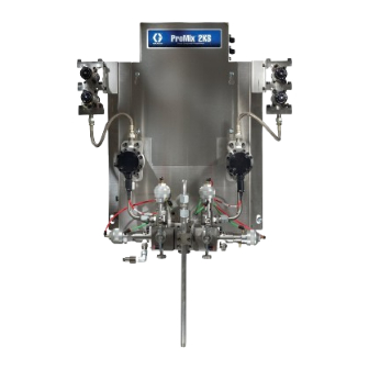
Wall Mount Fluid Panel
Graco Inc. P.O. Box 1441 Minneapolis, MN 55440-1441
Copyright 2006, Graco Inc. is registered to I.S. EN ISO 9001
™
Auto
RoboMix II
TI6803a
311189 rev.C
TI6802b
Advertisement
Table of Contents
Troubleshooting

Related Manuals for Graco ProMix Auto


Summary of Contents for Graco ProMix Auto
- Page 1 Important Safety Instructions Read all warnings and instructions in this manual. Save these instructions. Wall Mount Fluid Panel TI6802b RoboMix II TI6803a Graco Inc. P.O. Box 1441 Minneapolis, MN 55440-1441 Copyright 2006, Graco Inc. is registered to I.S. EN ISO 9001...
-
Page 2: Table Of Contents
Before Servicing ......17 Graco Standard Warranty ....46 After Servicing . -
Page 3: Promix ™ Auto Models
Do not exceed the pressure rating components may impair intrinsic safety. See page 5. of the lowest rated component. See page 5. Enter Model number here (See “ProMix Auto Smart Part Numbers” on page 4) ™ ProMix™ Auto Unit A &... -
Page 4: Promix Auto Smart Part Numbers
ProMix Auto Smart Part Numbers ProMix Auto Smart Part Numbers RoboMix II Fluid Panel RP (ProMix Auto) X = A & B Meter X = Color Options X = Catalyst X = Flow Control 1 = G250HR 0 = 1 Color... -
Page 5: Warnings
Warnings Warnings The following general warnings are for the setup, use, grounding, maintenance, and repair of this equipment. Addi- tional, more specific warnings may be found throughout the body of this manual where applicable. Symbols appear- ing in the body of the manual refer to these general warnings. When these symbols appear throughout the manual, refer back to these pages for a description of the specific hazard. - Page 6 Read fluid and solvent manufacturer’s warnings. For complete information about your material, request MSDS forms from distributor or retailer. • Check equipment daily. Repair or replace worn or damaged parts immediately with genuine Graco (ASM) replacement parts only. •...
-
Page 7: Promix ™ Auto Id Plate Locations
Component Manuals in U.S. English This manual (311189) is available in the following languages: Manual Description Manual Language Manual Language 311079 ProMix Auto Setup and Operation 311189 ProMix Auto Service - Parts 311189 English 311265 Chinese 310654 Fluid Mix Manifold... -
Page 8: Glossary Of Terms
Glossary of Terms Glossary of Terms Air Chop - the process of mixing air and solvent Fiber Optic Communication - the use of light to trans- together during the flush cycle to help clean the lines fer communication signals. and reduce solvent usage. Fill Time - the amount of time that is required to load Analog - relating to, or being a device in which data are mix material to the applicator. - Page 9 Glossary of Terms Mix - when cross-linking of the resin (A) and catalyst (B) Purge - when all mixed material is flushed from the sys- occurs. tem. Modbus/TCP - a type of communication protocol used Purge Time - the amount of time required to flush all to communicate Digital I/O signals over an ethernet.
-
Page 10: Pressure Relief Procedure
Pressure Relief Procedure Pressure Relief Procedure Follow Pressure Relief Procedure when you stop spraying, before changing spray tips, and before clean- ing, checking, or servicing equipment. Read warnings, page 5. Solenoid While in Mix mode (dispensing mix material), Button isolate the A and B fluid supply. Push the manual override on the A and B dispense valve solenoids to relieve pressure. -
Page 11: Shutdown
Shutdown Shutdown • To avoid electric shock, turn off EasyKey™ power before servicing. • Servicing EasyKey™ display exposes you to high voltage. Shut off power at main circuit breaker before opening enclosure. • All electrical wiring must be done by a qualified electrician and comply with all local codes and reg- ulations. -
Page 12: Troubleshooting
Troubleshooting Troubleshooting CAUTION Do not use the fluid in the line that was dispensed off ratio as it may not cure properly. ProMix™ Auto Alarms . 5: Setup Mode - Report Screen The ProMix™ Auto has alarms to alert you of a problem and prevent off-ratio spraying. -
Page 13: Solenoid Troubleshooting
Solenoid Troubleshooting Solenoid Troubleshooting Refer to the Pneumatic Diagram, page 27. If the dispense, purge, or dump valves are not turning on or off correctly, it could be caused by one of the following. Cause Solution Check air pressure. 80 psi (550 kPa, 5.5 bar) is commonly used. Do not go Air regulator pressure set too below 75 psi (517 kPa, 5.2 bar) or above 100 psi (0.7 MPa, 7 bar), high or too low. -
Page 14: Circuit Board Indicators
Solenoid Troubleshooting Circuit Board Indicators Part Number Board Button Display SW2 - Force software upgrade when D1 - 1-second heartbeat 249306 held at power-on. Ethernet none Two LEDs on bottom. Left is network 249183 connection. Right is network activity. Fluid none none 249179... - Page 15 Solenoid Troubleshooting D43 D34 D36 D28 . 8: Part Number 249190 311189C...
- Page 16 Solenoid Troubleshooting Network Activity Network Connection . 9: Part Numbers 249306 and 249183 311189C...
-
Page 17: Service
Service Service Before Servicing Close main air shutoff valve on air supply line and on ProMix™ Auto. Shut off ProMix™ Auto power (0 position). F . 10. If servicing EasyKey™ Display, also shut off power at main circuit breaker. • To avoid electric shock, turn off EasyKey™... -
Page 18: Replacing Air Filter Element
Service Replacing Air Filter Element There are three air filter elements: two on the Sole- noid Air Supply Control (part no. 570122) and one on the Wall Mount Fluid Panel. Unscrew filter bowl (B). Removing a pressurized air filter bowl could cause seri- ous injury. -
Page 19: Easykey™ Display
Service EasyKey™ Display Installing New Software Chip Follow Before Servicing procedure, page 17. • Updating Software • Replacing Power Supply Board Unlock and open EasyKey™ door with its key. • Replacing Power Supply Fuses Remove display board chip (C - F . - Page 20 Service Replacing Power Supply Board Turn on power at main circuit breaker. Turn EasyKey™ power on to test operation. Replacing Power Supply Fuses Servicing the power supply board exposes you to high ™ voltage. To avoid electric shock, turn off EasyKey power and shut off power at main circuit breaker before Servicing the power supply board exposes you to high servicing.
-
Page 21: Smart Fluid Panels
Service Smart Fluid Panels • Preparation • Replacing Control Board • Replacing Solenoids • Reassemble Fluid Panel Preparation Follow “Pressure Relief Procedure” on page 10 and “Shutdown” on page 11. Close main air shutoff valve on air supply line and on ProMix™... - Page 22 Service Replacing Control Board black with black, and hand-tighten connectors (E). . 22 and F . 22. CAUTION To avoid damaging circuit board when servicing, wear grounding strap on wrist and ground appropriately. Follow Preparation procedure, page 21. Loosen 6 screws (5) on bottom of panel to remove control board cover (6).
- Page 23 Service Follow Preparation procedure, page 21, and shut off power at main circuit breaker. Disconnect 2 solenoid wires (N) from control board 1 2 3 (2). F . 23 and F . 24 (wires not shown in F 24). Unscrew 2 screws (P) and remove the solenoid. Solenoid Actuates Standard...
- Page 24 Service Servicing Flow Meters • Coriolis Meter: To remove and service see Coriolis meter manuals. To service, see manual 310696. • G250 or G250HR Meter: To remove, follow proce- dure below. To service, see manual 308778. • G3000 or G3000HR Meter: To remove, follow pro- cedure below.
- Page 25 Service Servicing Fluid Manifold Installing Install the 3 screws behind the fluid manifold. Secure fluid manifold (5) and mounting plate (35) with 4 screws (34). Install A and B meter (1) bracket screws. See steps 9-11,Installing, Page 24. There are two different size integrators: 50cc and Connect air and fluid lines.
- Page 26 Service Servicing Color Change/Catalyst Assembly Removing Color Change Pneumatic Solenoid Follow “Pressure Relief Procedure” on page 10. Close main air shutoff valve on air supply line and on ProMix™ Auto. Shut off ProMix™ Auto power (0 position). Remove cover (A) by removing screws (B) and loosening screws (C not shown).
-
Page 27: Schematics
Schematics Schematics Pneumatic Diagram . 31 311189C... -
Page 28: Promix™ Auto Electrical Schematic
Schematics ProMix™ Auto Electrical Schematic . 32 311189C... -
Page 29: Notes
Notes Notes 311189C... -
Page 30: Parts
Parts Parts ProMix™ Auto Assembly Standard ProMix™ Auto Parts Table ProMix™ Auto Wall Mount Fluid Panel Ref. No. Description Component Options Table A side resin dump Ref. B side catalyst dump No. Option Part No. Description Qty. Color change control Flow Meter A Kit Color change valves None... - Page 31 Parts ProMix Auto Wall Mount Fluid Panel System Layout (RoboMix II end view) ProMix Auto RoboMix II System Layout 311189C...
-
Page 32: Wall Mount Fluid Panel
Parts Wall Mount Fluid Panel See table for part number Ref. Part No. Description Qty. Ref. 22† 15D320 CABLE, fiber optic Part No. Description Qty. 23★ 15G443 BRACKET, valve mount 24★ 287394 VALVE, dispense 280511 CONTROL, junction box; page 35 15G534 LABEL, identification 15D244 PLATE, mounting, manifold CONNECTOR, plug, 4 position... - Page 33 Parts TI7149a 311189C...
-
Page 34: Flow Meter Kits
Parts Flow Meter Kits Part No. 234564, G3000 Part No. 234566, G3000HR Ref. Part No. Description Qty. 239716 G3000 Flow Meter, 234564 only; see manual 308778 244292 G3000HR Flow Meter, 234566 only; see manual 308778 195283 Shield 166846 Adapter, 1/4 npt x 1/4 npsm 114339 Swivel Union;... -
Page 35: Control Junction Box
Parts Control Junction Box Part No. 280511 Ref. Part No. Description Qty. 552183 PLATE, 400 series MAC Ref. 100139 PLUG, pipe Part No. Description Qty. 114263 FITTING, connector, male SCREW, mach, phillips ENCLOSURE, solenoid HARNESS, connection 249190 BOARD, circuit assembly 112512 FERRULE, wire, orange SCREW, rd hd, 4-40 x .50 120075 CONNECTOR, plug, 14 position... -
Page 36: Robomix Ii (Replacement)
Parts RoboMix II (Replacement) Part Numbers: Ref. Part No. Description Qty. 249827 Basic 115223 FITTING, elbow, 3/8T x 1/4FNPT Flow Control 249828 166421 NIPPLE, pipe, 5/8 hex x 1-1/2, SST 104029 CLAMP, GND, elec Color Change 249829 111307 WASHER, lock, external, 5 mm NUT, hex Color and Catalyst Change 249830... - Page 37 Parts Reference Number/Quantity Assembly 249827 249828 249829 249830 249831 249832 TI7183a 311189C...
-
Page 38: Robomix Ii Mix Manifold
Parts RoboMix II Mix Manifold Part No. 287793 Ref. Part No. Description Qty. 101970 PLUG, pipe, HDLS 504235 FITTING, tube, bulkhead, female 116716 FITTING, elbow, 90 degree 692068 VALVE, DDV surface mount 119159 SWITCH, solvent MANIFOLD 9❄ 501867 VALVE, check 510223 FITTING, elbow, male 11❄... -
Page 39: Notes
Parts Notes 311189C... -
Page 40: Easykey™ Display
Parts EasyKey™ Display Part No. 249964 Kits Available: Part No. Description Ref. 197902 EasyKey™ Display Paint Shields, package Part No. Description Qty. of 10 ENCLOSURE 116320 SWITCH, rocker, power 249334 Mix Programmed Upgrade Kit; includes 117787 LATCH, quarter turn with key, software chip, chip extractor tool, and includes 3a grounding wrist strap. - Page 41 Parts 5, 6 TI7282b Alarm 311189C...
-
Page 42: Flow Control Regulator
Parts Flow Control Regulator Part No. 249849 Flow Ref. direction Part No. Description Qty. 1❄ 102980 NUT, full hex 2★❄ 111316 PACKING, o-ring 112698 ELBOW, male, swivel 4❄ 117610 O-RING FASTENER, shcs, 10-32X.5 PLATE, fluid, regulator 15F799 PLATE, air, regulator 9❄... -
Page 43: Color Change Control System
Parts Color Change Control System Part Numbers: 249868 2 color changes (3 valves) Model 249869 shown 4 color changes (5 valves) 249869 7 color changes (8 valves) 249870 Ref. Part No. Description Qty. MANIFOLD ENCLOSURE COVER 4★ 15G600 SOLENOID, valve, with flying lead 5★... -
Page 44: Notes
Notes Notes 311189C... -
Page 45: Technical Data
Dependent on programmed K-factor and application. The ProMix™ Auto maximum allowable flow meter pulse frequency is 425 Hz (pulses/sec.). For more detailed information on viscosities, flow rates, or mixing ratios, con- sult your Graco distributor. See individual component manuals for additional technical data. -
Page 46: Graco Standard Warranty
With the exception of any special, extended, or limited warranty published by Graco, Graco will, for a period of twelve months from the date of sale, repair or replace any part of the equipment determined by Graco to be defective.
Need help?
Do you have a question about the ProMix Auto and is the answer not in the manual?
Questions and answers