
Related Manuals for flamco GPAIII Series


Summary of Contents for flamco GPAIII Series
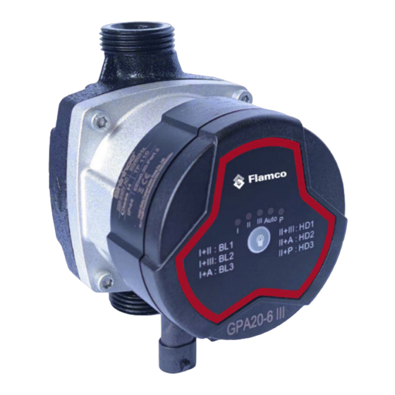
- Page 1 GPAIII series Energy-saving Pipeline Canned Motor Pump Installation and operating instruction www.flamcogroup.com...
-
Page 2: Table Of Contents
Table of Content Notes ������������������������������������������������������������������������������������������������������������������������3 1� Symbol description �������������������������������������������������������������������������������������������������4 2.1. GPA III series circulating pump for water circulation ..............4 2.2. Advantages of installation of the pump ..................4 3� Service conditions ���������������������������������������������������������������������������������������������������5 3.1. Ambient Temperature ......................... 5 3.2. Relative humidity (RH) ......................... 5 3.3. -
Page 3: Notes
Notes The installation manual should be read carefully before installation and use. Any failure to comply with the content marked by safety warning marks may cause personal injury, pump damage and other property loss, for which, the manufacturer shall not assume any responsibility and compensation. -
Page 4: 1� Symbol Description
Warning : Before starting installation, the Installation and Operating Instructions of device must be read carefully. Installation and use of the device must comply with local regulations and follow good operation specification. Warning : Personnel with physical decline, dysesthesia or poor mental ability and lacking of experience and relevant knowledge (including children) should use the pump under the supervision and guidance of people who can take charge of their safety. -
Page 5: 3� Service Conditions
3� Service conditions 3.1. Ambient Temperature Ambient temperature: 0°C~+70°C 3.2. Relative humidity (RH) Max. humidity: 95% 3.3. Media (conveying liquid) temperature Temperature of liquid conveying +2°C~+110°C. To prevent the control box and stator from appearing condensate water, the temperature of pump conveying liquid must be always higher than the ambient temperature. -
Page 6: Installation
4.1 Installation • Install the pump, arrows on the pump housing indicate the direction of liquid flowing through the pump body. • When the pump is installed on the pipeline, its inlet and outlet must be installed with two leather packings provided. •... -
Page 7: Thermal Insulation Of The Pump Body
Open the valve of inlet and outlet. Warning : Pumping liquid may be of high temperature and pressure, therefore, liquid in the system should be drained off or valves on both sides of the pump must be switched off before removing socket head cap screws. Change the position of junction box, the pump should not be started until the system has been filled with pumping liquid or valves on both sides of the pump are open. -
Page 8: 5� Electrical Connection
5� Electrical Connection Electrical connection and protection should be carried out in accordance with local regulations. Warning : The pump must be connected to earth wire. The pump must be connected with an external power switch; the minimum gap between all the electrodes is 3mm. •... -
Page 9: Light Area Displaying The Settings Of The Pump
Special Note: 1. 1. If I and II display at the same time, means BL1. If I and III display at the same time, If I and II display at the same time, means BL1. If I and III display at the same time, means BL2. -
Page 10: 7� Setting Of The Pump
7� Setting of the pump 7.1 The pump should be set according to system type Factory settings=AUTO (auto adaptation mode) Recommended and available settings of pump Settings of the pump Position System Type Optimal settings Or other optional settings Floor heating system AUTO Dual pipeline heating system AUTO... -
Page 11: The Control On The Pump
7.2 The control on the pump During the operation of pump, control it according to “proportional pressure control” (BL) principle or “constant pressure control” (HD) principle. In these two control modes, the performance of pump and corresponding power consumption should be adjusted according to the heat demand of system. 7.2.1 Proportional pressure control In this control mode, the pressure difference on both ends of the pump shall be controlled by flow. -
Page 12: Interface
8.2 Interface The pump is controlled by external electrical elements and components through interfaces. The interfaces convert external signals into signals that can be recognized by microprocessor in the pump. In addition, when the pump is supplied with 230V voltage, the interfaces can ensure that users will not be at risk of high voltage electric shock when contacting the... -
Page 13: Pwm Pwm Input Signal Profile Pwm2(Solar)
PWM Input Signal (%) Pump Status The pump switches to non-PWM mode (normal mode), and the default system will have no PWM signal input. <10 The pump runs at the highest velocity 10~84 The pump curve will drop from the highest to the lowest 85~91 The pump runs at the lowest velocity If the velocity variance point of input signal fluctuates, then it will block... -
Page 14: Pwm Feedback Signal
8.5 PWM Feedback Signal PWM feedback signal can provide operation status of the pump, such as power loss or all kinds of alarm/warning modes. PWM feedback signal will feed back exclusive alarming information. If the power voltage detects under voltage signal values, its output signal will be set to 75%. Provided sundries settlement exists in the hydraulic system and causes rotor being blocked, the duty cycle of output signal is set to 90%, the alarm will be given higher priority. -
Page 15: Manually-Operated Bypass Valve
A bypass valve system is fitted between the inlet pipeline and return pipeline. 9.1 Use of bypass valve Bypass valve The role of bypass valve is: when all the valves in the floor heating circuit or the temperature control valve of radiator are closed, it can be ensured that the heat from the boiler will be assigned. Elements in the system: •... -
Page 16: 10� Start Up
10� Start up 10.1 Before Start Up Before starting the pump, make sure that the system is filled with liquid, gas has been vented, and the pump inlet pressure must achieve the minimum inlet pressure as required (see Chapter 10.2 Exhaust the Motor Pump The pump has automatic gas- exhausting function. -
Page 17: 11� Settings And Performance Of Pump
11� Settings and performance of pump 11.1 Relationship between pump settings and its performance Pump Setting Functions Characteristics “Autoadaptation” function will automatically control the pump performance within the specified range. Highest to · Adjust the performance of the pump according to the size of AUTO Lowest system;... -
Page 18: 12� Performance Curve
12� Performance Curve 12.1 Performance curve guide Each setting of the pump will have a corresponding performance curve (Q/H curve). While AUTO autoadaptation mode covers a performance range. Input power curve (P1 curve) belongs to each Q/H curve. Power curve represents the power consumption (P1) of pump in watts on the given Q/H curve. -
Page 19: 13� Characteristics
·GPAXX-7.5 III Performance curve ·GPAXX-7.5 III Performance curve 13.Characteristics 13� Characteristics 13.Characteristics 13.1 Description of nameplate 13.1 Description of nameplate 13.1 Description of nameplate GPA III Power (max & min mode) Current (max & min mode) Explanation Maximum pressure bearing of system (Mpa) Maximum mode maximum power Power Product No. -
Page 20: Model Explanation
Certification mark Frequency (Hz) Temperature grade Energy efficiency label Model 13.2 Model explanation 13.2 Model explanation Pump model is consisted of upper Latin letters and Arabic numerals etc., whose meanings are Pump model is consisted of upper Latin letters and Arabic numerals etc., as follows: whose meanings are as follows: 29 : nine shifts + AUTO (Head Integration Model) -
Page 21: Installation Dimensions
Liquid Temperature Suction Inlet Pressure Min.(°C) Max.(°C) In domestic hot water, it is recommended to keep the temperature of water below 65 °C so as to reduce scaling 14.2 Installation Dimensions We reserve the right to change designs and technical specifications of our products. -
Page 22: 15� Fault Checklist
15� Fault checklist Warning : Before carrying out any maintenance and repair to the electric pump, make sure the power is disconnected and will not be accidentally switched on. Symptom Control Panel Cause Corrective Action Equipment fuse burned Replace the fuse The circuit beaker of current control or voltage control Connect the circuit breaker... - Page 23 Meaning of crossed –out wheeled dustbin: Do not dispose of electrical appliances as unsorted municipal waste, use separate collection facilities. Contact your local government for information regarding the collection systems available. If electrical appliances are disposed of in landfills or dumps, hazardous substances can leak into the groundwater and get into the food chain, damaging your health and well-being.
- Page 24 Copyright Flamco B.V., Almere, The Netherlands. No part of this publication may be reproduced or published in any way without explicit permission and mention of the source. The data listed are solely applicable to Flamco products. Flamco Limited shall accept no liability whatsoever for incorrect use, application or interpretation of the...
Need help?
Do you have a question about the GPAIII Series and is the answer not in the manual?
Questions and answers