Advertisement
Introduction
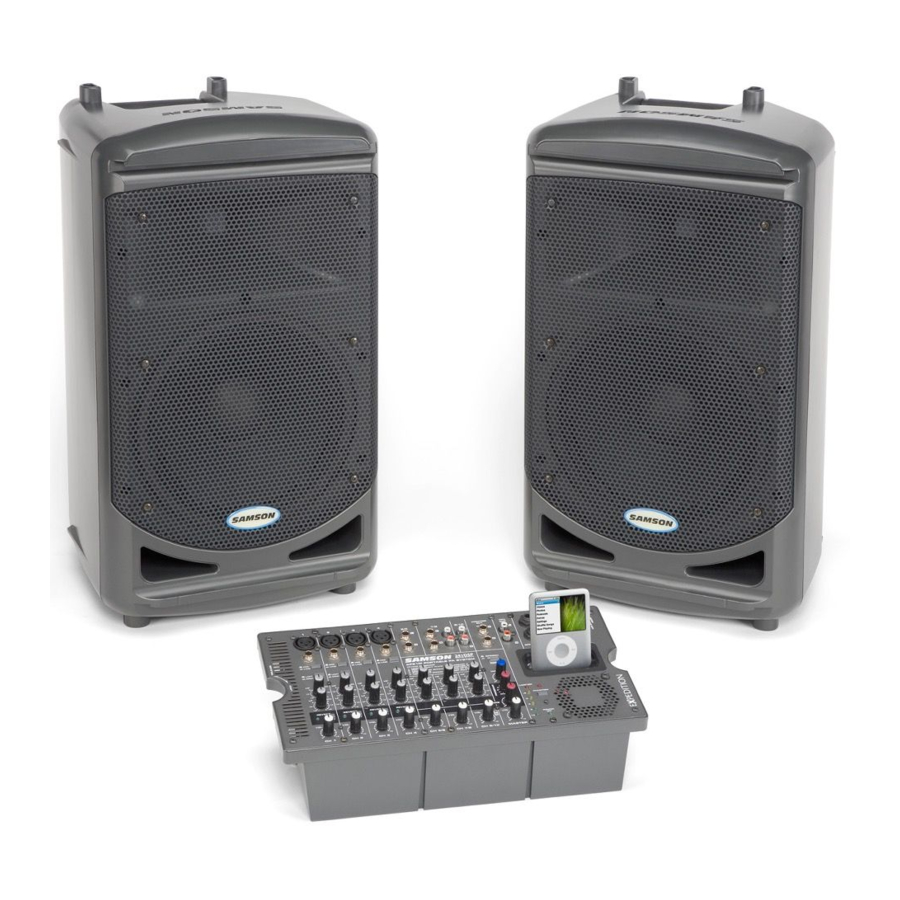
Thank you for purchasing the Expedition XP510i PORTABLE PA SYSTEM from Samson! The XP510i features a compact, 10-channel mixer with 500 watts of onboard power and dual 2-way speakers, making it an ideal solution for a variety of small to medium sized PA applications. The XP510i is extremely portable thanks to its lightweight and unique "Slide and Lock" design.
The 10-channel mixer can be removed from the speaker for tabletop use. It features 4 inputs for connecting microphones, plus three inputs for connecting stereo signals, like those from a CD player or electronic keyboard. There's also a built-in, 24-bit digital effects processor to add studio quality effects to your voice or instruments. For music playback, the XP510i features a convenient iPod dock. The mixer also provides a robust output, with 500 watts of total power from the lightweight, Class D amplifier section. The XP510i employs a matched speaker system with dual 2-way enclosures that have proprietary 10-inch woofers and 1-inch high frequency drivers. To help project the sound to a larger audience, the XP510i speakers can be mounted on standard speaker stands, thanks to the integral pole mount receptacles. The XP510i is constructed using durable ABS, high impact plastic, making it super road tough, and at the same time, lightweight.
Should your unit ever require servicing, a Return Authorization number (RA) must be obtained before shipping your unit to Samson. Without this number, the unit will not be accepted. Please call Samson at 1-800-3SAMSON (1-800-372-6766) for a Return Authorization number prior to shipping your unit. Please retain the original packing materials and if possible, return the unit in the original carton and packing materials. If you purchased your Samson product outside the United States, please contact your local distributor for warranty information and service.
Features
- The XP510i is a compact PA system with dual 2-way speakers, onboard mixer and 500 watt power amplifier.
- The XP510i is the ultimate in portable design. The lightweight and clever design allow you to connect all the pieces together into a single, easy to move case.
- The mixer is stored in one of the speaker cabinets; the other cabinet has an accessory compartment for storing the speaker cables, microphones, etc.
- The speakers are 2-way vented enclosures with 10-inch woofers for deep bass, complimented by a 1-inch high frequency driver, set in a custom horn with a 60 x 90 degree coverage pattern producing a clean, clear sound.
- The internal 2 x 250 watt lightweight Class D power amplifier produces a powerful stereo sound.
- The XP510i's mixer can be removed from the speaker for tabletop use and you can use the kick stand to set the mixer at an ergonomically correct angle.
- The 10-channel mixer features four Mic/Line inputs allowing you to connect microphones or line signals, plus three stereo inputs for connecting line signals from keyboards, drum machines and MP3/CD players. You can engage the Phantom Power switch if you are using condenser microphones.
- On each of the mixer's channel inputs there is a Bass and Treble control allowing you to equalize the tone of the individual inputs.
- To create a lush sound on any of the microphone channels, you can select from the ten, onboard, 24-bit digital effects.
- The XP510i features a built-in iPod dock allowing you to easily connect most iPod models for seamless music playback. You can use the iPod to simply play music, add background tracks, or repeat a commercial message at a fair or trade show.
- For added flexibility, the XP510i's mixer has a Monitor Out on two, 1/4 inch jacks allowing you to connect to external powered monitor speakers.
Quick Start
Unpacking and Setting Up the Device
- Unpack all the system components from the shipping carton and save all packing materials in the (unlikely) event your unit ever needs to be returned for service.
- Remove the mixer by turning the quarter turn screw counterclockwise towards the RELEASE position.

- Carefully hold the mixer to remove it from the speaker.

- Remove the accessory compartment cover by turning the quarter turn screw counterclockwise towards the RELEASE position, and remove the included speaker cables.

- Replace the accessory panel by aligning the bottom of the panel into the slots, make sure the quarter turn screw is in the RELEASE position; then close the panel and turn the quarter turn screw clockwise to LOCK.
- Position the speakers on the floor or on stands, and using one of the included speaker cables, connect the mixer's LEFT SPEAKER OUT to the left speaker's input connector. Next, use the second included speaker cable to connect the RIGHT SPEAKER OUT to the right speaker's input connector.


Using a Microphone
- Be sure that the XP510i's Power switch is set to the OFF position.
- Turn all of the channel VOLUME (VOL) controls fully counterclockwise to the "0" position.
- If the speakers are not connected, connect the speaker wires as described in the previous section.
- Next, connect the power cable to an AC outlet.
- Using a standard XLR cable, plug a microphone into the XP510i's Channel 1 MIC INPUT.

- Switch the XP510i's Power switch to the ON position.
- Set the MIC/LINE switch to the MIC position.
- Set the Channel 1 VOLUME (VOL) control to about halfway.
- While speaking into the microphone, slowly raise the MASTER level control until you have reached the desired level.

Using a Line Level Signal
- Be sure that the XP510i's Power switch is set to the OFF position.
- Turn all of the channel VOLUME (VOL) controls fully counterclockwise to the "0" position.
- Connect the power cable to an AC outlet.
- If using channels 1-4, set the MIC/LINE switch to the LINE position.
- Using standard 1⁄4-inch cables, connect a line level signal from a keyboard into the XP510i's LINE INPUTS.

- Switch the XP510i's Power switch to the ON position.
- Play your guitar or keyboard and slowly raise the channel control and the MASTER level control until you have reached the desired VOLUME.

Configuring the Unit for Transport
You can easily carry your sound system using the XP510i's "Slide and Lock" feature. The "Slide and Lock" speaker enclosures allow you to connect both speakers together into a single, easy to carry unit. Follow these steps to configure the XP510i for easy transport.
- Place one speaker on the floor and set it on its side.
![]()
- Position the second speaker above the first speaker and line up the "Slide and Lock" tracks and grooves so that they are parallel to the speaker on the floor.
![]()
Speaker cabinets must be reversed with respect to top and bottom. - Slide the second speaker into the speaker on the floor making certain that the two speakers stay parallel to each other. in place.

- You will feel a slight click when the two speakers are in place.
![]()


Wiring Guide
CONNECTING THE DEVICE
There are several ways to interface the XP510i to support a variety of applications. The XP510i features balanced inputs and outputs, so connecting balanced and unbalanced signals is possible.

Specifications
System Specifications
Maximum Output Power
250 W + 250 W @ 8 Ω
Maximum Output Level (0.5% T.H.D. @ 1kHz)
+22dBu(MONITOR L/R) @ 10 kΩ
+14 dBu (REC) @ 10 kΩ
T.H.D
<0.1% @+14 dB 20 Hz ~ 20 kHz (MONITOR L/R,REC L/R) @ 10 kΩ
Frequency Response
20 Hz ~ 20 kHz +/-1 dB, 10 kΩ (MONITOR L/R)
20 Hz ~ 20 kHz +0/-1 dB, 10 kΩ (REC L/R)
Hum and Noise (Input GAIN=Maximum Input sensitivity, MIC)
-112dBu equivalent input noise ( Rs = 150 Ω )
-90dBu Residual noise (MONITOR L/R) all Levels at Minimum
-80dBu MONITOR at nominal level and all channel Levels minimum.
-70dBu MONITOR at maximum level and all channel Levels minimum.
Maximum Voltage Gain
50dB MIC 1/2(XLR,LIMIT Position) IN TO MONITOR L/R
60dB MIC 3/4(XLR) IN TO MONITOR L/R
40dB MIC 1/2(PHONE TRS,LIMIT Position) IN TO MONITOR L/R
50dB MIC 3/4(PHONE TRS) IN TO MONITOR L/R
14dB CH 1/2 LINE(PHONE TRS,LIMIT Position, MIC/LINE SW IN) IN TO MONITOR L/R
24dB CH 3/4 LINE(PHONE TRS,MIC/LINE SW IN) IN TO MONITOR L/R
28dB ST LINE IN TO MONITOR L/R
48dB MIC 3/4(XLR) IN TO REC L/R
Crosstalk (at 1 kHz)
-70 dB between input channels
-70 dB between input/output channels
SPEECH/MUSIC
167 Hz, 3dB/Octave
Input Channel Equalization
HIGH: 10 kHz shelving ±15 dB
LOW: 100 Hz shelving ±15 dB
LIMIT/COMP Switch
DOWN = Comp, UP = Limit (CH1/2)
Phantom Power
+15V DC
Power Source/Power Consumption
AC INPUT 100 V~240 V, 50/60 Hz, 600 W MAX.
Weight
52.8 Ib (24 Kg)
Dimensions
22.7''(W) x 12.6''(D) x 22''(H)
577 mm(W) x 320 mm(D) x 560 mm(H)
Where 0 dBu = 0.775 V and 0 dBV = 1 V
Input Specifications
| Input Connector | Input Impedance | Nominal Source Impedance | Rated Input Level | Connector Type |
| CH MIC | 3.6 kΩ / 7.5 kΩ | 50 ~ 600 Ω / 600 Ω | -32 dBu / -22dBu | XLR Type Balanced / Phone Jack (TRS) T=Hot R=Cold S=GND |
| CH LINE | 3.6 kΩ / 7.5 kΩ | 50 ~ 600 Ω / 600 Ω | -6 dBu / +4 dBu | XLR Type Balanced / Phone Jack (TRS) T=Hot R=Cold S=GND |
| STEREO INPUT | 10 kΩ | 600 Ω | 0 dBu | Unbalanced Phone Jack |
| STEREO INPUT | 10 kΩ | 600 Ω | 0 dBu | RCA pin Jack |
Output Specifications
| Output Connector | Output Impedance | Nominal Load Impedance | Rated Output Level | Connector type |
| MONITOR L/R | 1 kΩ | ≥10 kΩ | +4 dBu | Phone Jack (TRS) Impedance balanced T=hot R=Cold S=ground |
| REC OUT | 600 Ω | ≥10 kΩ | +4 dBu | RCA pin Jack |
| SPEAKER OUTPUT | 8 Ω | 250 W | Phone Jack |
Dimensions

Device Mixer Layout

- Channel Input Jacks (channels 1 - 4)
MIC – XLR connector – Use these XLR jacks to connect low impedance microphones to the XP510i's built-in mic preamps.
LINE - 1/4-inch phone connector – Use these 1/4" jacks to connect instrument or audio sources with line-level signals to the XP510i. You can connect the outputs from acoustic guitar pickups, keyboards, drum machines, CD/MP3/TAPE players and other units with line level outputs here. - Stereo Channel Input Jacks (channels 5/6, 7/8, 9/10)
For stereo inputs, use the LINE L to connect the left channel and the LINE R to connect the right channel. Use these inputs to connect high impedance microphones, synthesizers, drum machines, MP3, CD, tape players or any other line level device. The XP510i features both 1/4" phone and RCA connectors. - MIC/LINE switch (channels 1 - 4)
The MIC position changes the gain of both input jacks to MIC level. The LINE position reduces the gain of both jacks by 30dB to line level. - LIMIT/COMP switch
Set the LIMIT/COMP switch to the COMP position to apply compression or set it to the LIMIT position to apply limiting. - Equalizer control knobs
HIGH FREQUENCY (HF) – The HF knob controls the amount of Treble applied to each channel. The channel's HIGH frequency response is flat when the knob is in the "12:00" position. Rotating the knob to the right will boost the channel's high frequency response above 10 kHz by 15 dB, and rotating it towards the left will cut the high frequency response by 15 dB.
LOW FREQUENCY (LF) – The LF knob controls the amount of Bass applied to each channel. The channel's LOW frequency response is flat when the knob is in the "12:00" position. Rotating the knob to the right will boost the channel's low frequency response below 100 Hz by 15 dB, and rotating it towards the left will cut the low frequency response by 15 dB. - REVERB switch
Use the REVERB switch to add an effect to a Mic or Line input on any of the inputs 1 – 4. The REVERB LED indicator lights GREEN when the REVERB is ON. - VOLUME control knob
This knob sets the overall level for the Mic or Line input.
NOTE: To reduce noise, set the VOLUME controls on any unused channels to the minimum setting. - MONITOR OUT jacks
The signal present at the MONITOR OUT jacks is sent from the MONITOR level control knob, which is fed from the input channels. The MASTER control does not affect the MONITOR OUT signal. - REC OUT jacks
This output is used to send the main mix to an external recorder. The signal present at this connector is the L/R bus signal before it has passed through the MASTER level control. The nominal output level is -10 dBV and the impedance is 100 Ohms. - SPEAKER OUT jacks
The XP510i has two 1/4-inch phone connectors, which are powered outputs used to connect your left and right speaker. Use the included speaker cables to connect the speakers.
![]()
The total impedance load for each side of the amplifier must not be less than 8 Ohms. Do not connect additional speakers to the XP510i mixer. - AC – IEC inlet
Connect the supplied heavy-gauge 3-pin "IEC" power cable here. - POWER switch
Use the POWER switch to turn power to the XP510i on or off. - iPOD DOCK
The XP510i has a built-in iPod dock which can be used to connect most of the latest iPod models. The iPod signal is controlled by the Channel 9/10 VOLUME control. - SPEECH/MUSIC switch
The SPEECH/MUSIC switch is used to change the overall frequency response, or tone contour, for the XP510i sound system. If your application is mainly for MUSIC, press the switch down to select the MUSIC response curve. If your application is mainly for SPEECH, leave the switch up to select the SPEECH response curve. - MONITOR control knob
The MONITOR volume control is used to control the overall level sent to the MONITOR OUT, which can be used to send to a second set of powered speakers for monitors. - REVERB PROGRAM selector
This control knob is used to select one of ten, 24-bit DSP effects programs. - REVERB control knob
The REVERB control knob is used to adjust the total amount of reverb added to any channel that has its REVERB switch (see #6) pressed down. - MASTER control knob
The MASTER volume knob controls the overall output level. This knob determines the final output signal level. Signals from all ten channels are routed here just before being routed to the built-in power amplifiers and Left and Right speaker output jacks (see #10). - METER LED indicators
This six-segment bar meter shows the XP510i's output level. For optimum signal-to-noise ratio, set the VOLUME control so that program material is usually at or around +3 to +6 VU, with occasional, but not steady excursions to the red "LIMIT" segment. - PHANTOM switch
The XP510i features an onboard, Phantom power supply to operate condenser microphones. When the switch is engaged, the LED will illuminate indicating that phantom power is now available on the microphone pre-amps.
![]()
To avoid a loud pop, be sure to turn down the MASTER level control before plugging and unplugging the mic cables when the phantom power is active. - POWER LED indicator
The Power LED will illuminate when the MAIN power switch is turned on.


Applying Reverb
The XP510i features built-in, high quality, 24-bit Reverb Effects that you can add to channels 1 through 4. You can use the reverb to create a studio effect by simply following the steps below:
- Connect a mic or instrument to the desired channel, and adjust the volume and equalizer to your liking.
- Use the Reverb Program selector to choose one of the ten built-in digital effects.

- Press the REVERB switch down on the channel to which you want to add the reverb effect.

- Once you have selected the channel(s) for effects by using the channel REVERB switch, raise the REVERB main level control to apply the amount of reverb desired.


System Set-ups

Block Diagram


Documents / ResourcesDownload manual
Here you can download full pdf version of manual, it may contain additional safety instructions, warranty information, FCC rules, etc.
Download Samson EXPIDITION XP510i - Portable PA System Manual
Advertisement


Need help?
Do you have a question about the EXPIDITION XP510i and is the answer not in the manual?
Questions and answers