Table of Contents
Advertisement
Quick Links
LINEAR ACTUATORS
UAL 0 – UBA 0
Installation, operation and maintenance manual
Publication: 04.00.E - Rev. 02 Date (M/Y) 07/21
Servomech S.p.A.
Via M. Calari, 1 - 40011 Anzola dell'Emilia (BO) - ITALY
Ph: + 39 051 6501711 Fax: + 39 051 734574
www.linearmech.com sales@linearmech.com
Servomech S.p.A.
04.00.E - Rev. 02 Date (M/Y) 07/21
1
Advertisement
Table of Contents

Subscribe to Our Youtube Channel
Related Manuals for Servomech UAL 0


Summary of Contents for Servomech UAL 0
- Page 1 LINEAR ACTUATORS UAL 0 – UBA 0 Installation, operation and maintenance manual Publication: 04.00.E - Rev. 02 Date (M/Y) 07/21 Servomech S.p.A. Via M. Calari, 1 - 40011 Anzola dell’Emilia (BO) - ITALY Ph: + 39 051 6501711 Fax: + 39 051 734574 www.linearmech.com sales@linearmech.com...
- Page 2 The aforementioned conditions are therefore not contemplated and entail the immediate termination of the guarantee and the immediate decay of any responsibility on the part of Servomech S.p.A. Servomech S.p.A. reserves the right to make changes to the actuators and this manual without giving any notice. Servomech S.p.A.
-
Page 3: Table Of Contents
FCM magnetic stroke limit switches ....................10 Rotary encoder EH38 ........................12 Electric motor wiring ........................13 Linear actuator installation ......................14 Installation of rod end fitting elements ....................15 COMMISSIONING AND USE ........................16 LUBRICATION ............................17 MAINTENANCE ............................17 Servomech S.p.A. 04.00.E - Rev. 02 Date (M/Y) 07/21... -
Page 4: Models Covered By This Document
1 MODELS COVERED BY THIS DOCUMENT The present manual is referred to following products: Acme screw linear actuators: UAL 0 Ball screw linear actuators: UBA 0 2 IDENTIFICATION OF THE MANUFACTURER AND THE PRODUCT 2.1 Identification of the manufacturer SERVOMECH S.p.A. S.U. -
Page 5: Identification Of The Product
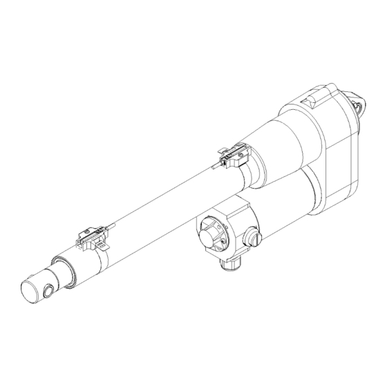
B/N: production batch number (gives the full traceability of products); WK/YEAR: week and year of manufacturing of the product. 2.4 Identification label position Following pictures show label positioning on actuator. Identification label Servomech S.p.A. 04.00.E - Rev. 02 Date (M/Y) 07/21... -
Page 6: Trasport And Handling
In the case of UBA 0 actuators, the ball screw inside the actuator is NOT self-locking. Never lift the linear actuator upright from the push rod as the actuators could be back driven by its own weight. In case of doubt, consult SERVOMECH S.p.A. to get the appropriate information and prevent any kind of damage! -
Page 7: Use Restrictions
× 100 �� 10 ������ Actuator Fu [%] UAL 0 UBA 0 For the proper operation of acme screw linear actuator (UAL 0) do never exceed the permissible duty cycle limit. Servomech S.p.A. 04.00.E - Rev. 02 Date (M/Y) 07/21... -
Page 8: Personnel Requirements / Qualifications
DO NOT DISCONNECT ANY CONNECTION DURING OPERATION OR IN PRESENCE OF SUPPLY VOLTAGE. BEFORE TO TURN-ON THE MOTOR, MAKE SURE THE MECHANICAL CONNECTIONS OF THE ACTUATOR REMAIN TIGHTENED AND STABLE, ALSO DURING THE OPERATION. Servomech S.p.A. 04.00.E - Rev. 02 Date (M/Y) 07/21... - Page 9 DURING OPERATION, TEMPERATURE OF THE EXTERNAL SURFACE OF MOTORS CAN REACH HIGH TEMPERATURES. HOT SURFACES ON ACTUATOR CAN CAUSE BURNS AND SHOULD NOT BE TOUCHED. DO NOT FASTEN OR PLACE NEAR THE MOTOR THERMO SENSITIVE COMPONENTS: DAMAGES MAY OCCUR. Servomech S.p.A. 04.00.E - Rev. 02 Date (M/Y) 07/21...
-
Page 10: Fcm Magnetic Stroke Limit Switches
DO NOT SET THE FC 2 SWITCH POSITION OVER THE LIMIT MARK ON THE TUBE. DO NOT TRAVEL OVER THE STROKE LIMIT SWITCHES POSITIONS, AVOIDING TO REACH MECHANICAL STOP AND PREVENTING DAMAGE TO THE INTERNAL COMPONENTS OF THE ACTUATOR. Servomech S.p.A. 04.00.E - Rev. 02 Date (M/Y) 07/21... - Page 11 Multicore PVC cable 2 × 0.12 mm Outlet length 2 m BN = brown Wiring BU = blue Main fuse F < 0.8A IEC60127-2 sheet 1 Main fuse F < 0.5A IEC60127-2 sheet 1 Servomech S.p.A. 04.00.E - Rev. 02 Date (M/Y) 07/21...
-
Page 12: Rotary Encoder Eh38
Following table shows n° of pulses for 1 mm of stroke, for each size and ratio: Encoder resolution N° of pulses for 1 mm of stroke 100 ppr 500 ppr UAL 0 UBA 0 Servomech S.p.A. 04.00.E - Rev. 02 Date (M/Y) 07/21... -
Page 13: Electric Motor Wiring
Figure 6.3 – Electric wiring diagrams to power supply of DC motor BROWN RED +Vdc BROWN +Vdc -Vdc BLUE BLUE BROWN -Vdc +Vdc BLUE BLACK -Vdc Figure 6.4 – Electric wiring of DC motor Servomech S.p.A. 04.00.E - Rev. 02 Date (M/Y) 07/21... -
Page 14: Linear Actuator Installation
DO NOT SET THE LENGTH OF THE ACTUATOR OVER ITS EXTREME VALUES: “Lc” = RETRACTED ACTUATOR “La” = EXTENDED ACTUATOR Figure 6.6 – “Lc” and “La” dimensions Dimensions “Lc” and “La” are indicated in the technical catalogue of the product. Servomech S.p.A. 04.00.E - Rev. 02 Date (M/Y) 07/21... -
Page 15: Installation Of Rod End Fitting Elements
To unmount the element, heat the threaded area to unlock it. Unscrew the fitting element counterholding the torque with a wrench flat on the rod end. Figure 6.8 – Installation of rod end fitting element Servomech S.p.A. 04.00.E - Rev. 02 Date (M/Y) 07/21... -
Page 16: Commissioning And Use
Carry out some complete working cycles, increasing gradually the load, until full load is reached. FOR ACME SCREW LINEAR ACTUATOR UAL 0: DURING COMMISSIONING, DO NEVER EXCEED THE MAX ALLOWED DUTY CYCLE FOR THE LINEAR ACTUATOR 30% OVER 10 MIN TIME PERIOD AT 25°C ENVIRONMENT. -
Page 17: Lubrication
DO NOT USE LUBRICANTS DIFFERENT FROM THOSE ABOVE MENTIONED. DO NOT MIX INCOMPATIBLE GREASES. IF DIFFERENT LUBRICANT SHOULD BE USED, PLEASE CONTACT SERVOMECH BEFORE PROCEED. IN CASE OF CUSTOM PRODUCT EXECUTION, THE LUBRICANTS COULD BE DIFFERENT FROM THE STANDARD ABOVE.
Need help?
Do you have a question about the UAL 0 and is the answer not in the manual?
Questions and answers