Table of Contents
Advertisement
Quick Links
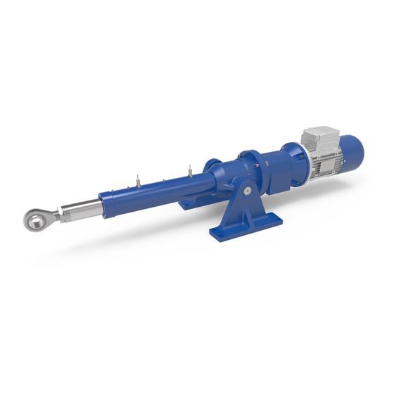
LINEAR ACTUATORS
ILA 15 A – ILA 25 A – ILA 50 A – ILA 100 A – ILA 150 A – ILA 200 A
ILA 15 B – ILA 25 B – ILA 50 B – ILA 100 B – ILA 150 B – ILA 200 B
Installation, operation and maintenance manual
Publication: 21.15-25-50-100-150-200.I - Rev. 01 Data (M/Y) 10/19
Servomech S.p.A.
Via M. Calari, 1 - 40011 Anzola dell'Emilia (BO) - ITALY
Ph: + 39 051 6501711 Fax: + 39 051 734574
www.servomech.com info@servomech.com
Servomech S.p.A.
21.15-25-50-100-150-200.E - Rev. 01 DD (M/Y) 10/19
1
Advertisement
Table of Contents

Subscribe to Our Youtube Channel
Related Manuals for Servomech ILA Series


Summary of Contents for Servomech ILA Series
- Page 1 ILA 15 B – ILA 25 B – ILA 50 B – ILA 100 B – ILA 150 B – ILA 200 B Installation, operation and maintenance manual Publication: 21.15-25-50-100-150-200.I - Rev. 01 Data (M/Y) 10/19 Servomech S.p.A. Via M. Calari, 1 - 40011 Anzola dell’Emilia (BO) - ITALY Ph: + 39 051 6501711 Fax: + 39 051 734574 www.servomech.com info@servomech.com...
- Page 2 The aforementioned conditions are therefore not contemplated and entail the immediate termination of the guarantee and the immediate decay of any responsibility on the part of Servomech S.p.A. Servomech S.p.A. reserves the right to make changes to the actuators and this manual without giving any notice. Servomech S.p.A.
-
Page 3: Table Of Contents
Installation of rod end fitting elements ....................17 COMMISSIONING AND USE ........................18 LUBRICATION ............................19 MAINTENANCE ............................20 Linear drive lubrication ........................21 Push rod guides lubrication ......................22 Hinged head TF lubrication.......................22 Thrust bearings lubrication ......................23 Servomech S.p.A. 21.15-25-50-100-150-200.E - Rev. 01 DD (M/Y) 10/19... -
Page 4: Models Covered By This Document
Ball screw linear actuators: ILA 15 B – ILA 25 B – ILA 50 B – ILA 100 B – ILA 150 B – ILA 200 B 2 IDENTIFICATION OF THE MANUFACTURER AND THE PRODUCT 2.1 Identification of the manufacturer SERVOMECH S.p.A. S.U. Via Monaldo Calari, 1 40011 Anzola dell’Emilia (BO) ITALY Ph. -
Page 5: Identification Of The Product
2.3 Identification of the product Every SERVOMECH linear actuator is provided with a nameplate, as shown below, which allows the product identification and gives technical information about the product. Figure 2.2 – Identification nameplate 1) Product code: is an alphanumeric code stating the type, size, ratio, version and stroke end switches of the linear actuator;... -
Page 6: Trasport And Handling
Extra-mass for each additional 100 mm [kg] stroke length In case of doubt, consult SERVOMECH S.p.A. to get the appropriate information and prevent any kind of damage! Servomech S.p.A. 21.15-25-50-100-150-200.E - Rev. 01 DD (M/Y) 10/19... -
Page 7: Use Restriction
They must be subjected to the loading and speed conditions specified in the catalog. Modification of parts of the actuator or replacement of components with different and non-original parts is not permitted. The replacement of components with original spare parts is carried out only by Servomech S.p.A. -
Page 8: Standard Operating Conditions
4.1.2 Standard operating conditions The actuator must be used in an environment whose conditions comply with the provisions of Servomech S.p.A. The works necessary for obtaining and maintaining that conditions are in charge of the owner and, where applicable, are in charge of the end user. -
Page 9: Installation
MAKE SURE THE SAFETY PROTECTION OF THE MACHINE (MECHANICAL AND ELECTRICAL) ARE ACTIVE. DURING OPERATION, TEMPERATURE OF THE EXTERNAL SURFACE OF MOTORS CAN REACH HIGH TEMPERATURES. HOT SURFACES ON ACTUATOR CAN CAUSE BURNS AND SHOULD NOT BE TOUCHED. Servomech S.p.A. 21.15-25-50-100-150-200.E - Rev. 01 DD (M/Y) 10/19... -
Page 10: Fcp Inductive Proximity Stroke Limit Switches
Multicore PVC cable 3 × 0.2 mm Outlet length 2 m Wiring DO NOT TRAVEL OVER THE STROKE LIMIT SWITCHES POSITIONS, AVOIDING TO REACH MECHANICAL STOP AND PREVENTING DAMAGE TO THE INTERNAL COMPONENTS OF THE ACTUATOR. Servomech S.p.A. 21.15-25-50-100-150-200.E - Rev. 01 DD (M/Y) 10/19... -
Page 11: Fc Electric Stroke Limit Switches
2 PVC multicore cables 2 × 0.75 mm Output length 1.5 m Wiring DO NOT TRAVEL OVER THE STROKE LIMIT SWITCHES POSITIONS, AVOIDING TO REACH MECHANICAL STOP AND PREVENTING DAMAGE TO THE INTERNAL COMPONENTS OF THE ACTUATOR. Servomech S.p.A. 21.15-25-50-100-150-200.E - Rev. 01 DD (M/Y) 10/19... -
Page 12: Electric Motor Wiring
K1, K2, K3 = contactor M = motor Br = brake Figure 6.3 – Electric wiring diagrams to power supply of AC 3-ph motor Servomech S.p.A. 21.15-25-50-100-150-200.E - Rev. 01 DD (M/Y) 10/19... - Page 13 Figure 6.4 – Electric wiring diagrams to motor terminal board of AC 3-ph motor IN CASE OF ELECTRIC MOTOR DIFFERENT FROM THE ABOVE MENTIONED, PLEASE REFER TO INSTALLATION INSTRUCTIONS SUPPLIED BY THE MANUFACTURER. Servomech S.p.A. 21.15-25-50-100-150-200.E - Rev. 01 DD (M/Y) 10/19...
-
Page 14: Ac 1-Phase Asynchronous Motor With Balanced Winding
Figure 6.6 – Electric wiring diagrams to motor terminal board of AC 1-ph motor IN CASE OF ELECTRIC MOTOR DIFFERENT FROM THE ABOVE MENTIONED, PLEASE REFER TO INSTALLATION INSTRUCTIONS SUPPLIED BY THE MANUFACTURER. Servomech S.p.A. 21.15-25-50-100-150-200.E - Rev. 01 DD (M/Y) 10/19... -
Page 15: Dc Motor
Figure 6.8 – Electric wiring diagrams to motor terminal board of DC motor IN CASE OF ELECTRIC MOTOR DIFFERENT FROM THE ABOVE MENTIONED, PLEASE REFER TO INSTALLATION INSTRUCTIONS SUPPLIED BY THE MANUFACTURER. Servomech S.p.A. 21.15-25-50-100-150-200.E - Rev. 01 DD (M/Y) 10/19... -
Page 16: Linear Actuator Installation
“La” = EXTENDED ACTUATOR Figure 6.9 – “Lc” and “La” dimensions Dimensions “Lc” and “La” are indicated in the technical catalogue of the product and on the check sheet supplied with the actuator. Servomech S.p.A. 21.15-25-50-100-150-200.E - Rev. 01 DD (M/Y) 10/19... -
Page 17: Installation Of Rod End Fitting Elements
Fix the threaded element with Loctite 270. To unmount the element, heat the threaded area to unlock it. Unscrew the fitting element counterholding the torque on the push rod. Servomech S.p.A. 21.15-25-50-100-150-200.E - Rev. 01 DD (M/Y) 10/19... -
Page 18: Commissioning And Use
7 COMMISSIONING AND USE SERVOMECH linear actuators are supplied lubricated and ready to be used. Before to start commissioning and activation, the following checks must be carried out: Shifting direction check Check if the push rod shifting direction is compatible to the indications on the control unit, by powering the electric motor on VERY BRIEFLY. -
Page 19: Lubrication
8 LUBRICATION SERVOMECH linear actuators ILA series are supplied lubricated, with lubricants indicated in the table below: PUSH ROD HINGED ACTUATOR BEARINGS LINEAR DRIVE GUIDES HEAD TF ILA 15 A Grease (NLGI 2 DIN Grease (NLGI 2 DIN 51818): ILA 15 A... -
Page 20: Maintenance
Every 2 months time interval: visual inspections of actuator conditions, cleaning of dirty parts of the actuator. In case of lubricant leakage from the gearbox, contact SERVOMECH. ACTUATOR Lead pitch Lubrication interval Linear drive lubrication q.ty Push rod guides Hinged head Q.ty for actuator... -
Page 21: Linear Drive Lubrication
At the end of lubricating procedure, extend and retract the push rod over its entire stroke for 3 full cycles. If necessary, remove excess of lubricant from push rod. Servomech S.p.A. 21.15-25-50-100-150-200.E - Rev. 01 DD (M/Y) 10/19... -
Page 22: Push Rod Guides Lubrication
Hinged head TF grease nipple Figure 9.4 – Hinged head TF lubrication Apply the grease until the steel bush is filled. If necessary, remove excess of lubricant from the hinge pin. Servomech S.p.A. 21.15-25-50-100-150-200.E - Rev. 01 DD (M/Y) 10/19... -
Page 23: Thrust Bearings Lubrication
Restore the lubricant quantity of thrust bearings using proper grease nipple, as shown on Fig. 9.5. Grease nipple type: DIN71412 M6 The quantity of lubricant to be added depends on the leaked volume. Servomech S.p.A. 21.15-25-50-100-150-200.E - Rev. 01 DD (M/Y) 10/19...
Need help?
Do you have a question about the ILA Series and is the answer not in the manual?
Questions and answers