Table of Contents
Advertisement
Quick Links
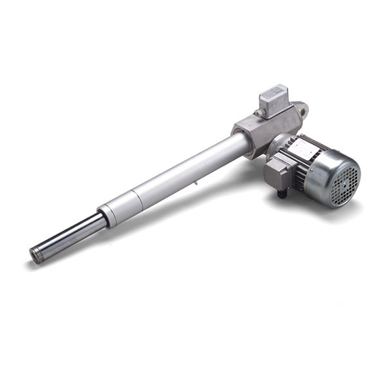
LINEAR ACTUATORS
CLA 20 – CLA 25 – CLA 25S/M – CLA 28 – CLA 28T
CLB 25 – CLB 27
Installation, operation and maintenance manual
Publication: 16.20-25-27-28.E - Rev. 00 Date (M/Y) 12/19
Servomech S.p.A.
Via M. Calari, 1 - 40011 Anzola dell'Emilia (BO) - ITALY
Ph: + 39 051 6501711 Fax: + 39 051 734574
www.linearmech.com sales@linearmech.com
Servomech S.p.A.
16.20-25-27-28.E - Rev. 00 DD (M/Y) 12/19
1
Advertisement
Table of Contents

Related Manuals for Servomech Linearmech CLA 20


Summary of Contents for Servomech Linearmech CLA 20
- Page 1 CLB 25 – CLB 27 Installation, operation and maintenance manual Publication: 16.20-25-27-28.E - Rev. 00 Date (M/Y) 12/19 Servomech S.p.A. Via M. Calari, 1 - 40011 Anzola dell’Emilia (BO) - ITALY Ph: + 39 051 6501711 Fax: + 39 051 734574 www.linearmech.com sales@linearmech.com...
- Page 2 The aforementioned conditions are therefore not contemplated and entail the immediate termination of the guarantee and the immediate decay of any responsibility on the part of Servomech S.p.A. Servomech S.p.A. reserves the right to make changes to the actuators and this manual without giving any notice. Servomech S.p.A.
-
Page 3: Table Of Contents
Set up of POR 5k potentiometer ......................19 Safety clutch FS ..........................20 Electric motor wiring ........................21 6.8.1 AC 3-phase asynchronous motor .....................21 6.8.2 AC 1-phase asynchronous motor with balanced winding ............22 6.8.3 DC motor ..........................23 Servomech S.p.A. 16.20-25-27-28.E - Rev. 00 DD (M/Y) 12/19... - Page 4 Linear actuator installation ......................24 6.10 Installation of rod end fitting elements ....................25 COMMISSIONING AND USE ........................26 LUBRICATION ............................27 MAINTENANCE ............................27 Servomech S.p.A. 16.20-25-27-28.E - Rev. 00 DD (M/Y) 12/19...
-
Page 5: Models Covered By This Document
Acme screw linear actuators: CLA20 – CLA25 – CLA25S – CLA25M – CLA28 – CLA28T Ball screw linear actuators: CLB28 – CLB27 2 IDENTIFICATION OF THE MANUFACTURER AND THE PRODUCT 2.1 Identification of the manufacturer SERVOMECH S.p.A. S.U. Via Monaldo Calari, 1 40011 Anzola dell’Emilia (BO) ITALY Ph. -
Page 6: Identification Of The Product
B/N: production batch number (gives the full traceability of products); WK/YEAR: week and year of manufacturing of the product. 2.4 Identification label position Following picture shows label positioning on actuator. Identification label Servomech S.p.A. 16.20-25-27-28.E - Rev. 00 DD (M/Y) 12/19... -
Page 7: Trasport And Handling
In the case of BSA series actuators, the ball screw inside the actuator is NOT self-locking. Never lift the linear actuator upright from the push rod as the actuators could be back driven by its own weight. In case of doubt, consult SERVOMECH S.p.A. to get the appropriate information and prevent any kind of damage! -
Page 8: Use Restrictions
WITH SERVOMECH, SINCE A SPECIAL EQUIPMENT OF THE PRODUCT MUST BE PROVIDED. 4.1.2 Standard operating conditions The actuator must be used in an environment whose conditions comply with the provisions of Servomech S.p.A. The works necessary for obtaining and maintaining that conditions are in charge of the owner and, where applicable, are in charge of the end user. -
Page 9: Personnel Requirements / Qualifications
DO NOT DISCONNECT ANY CONNECTION DURING OPERATION OR IN PRESENCE OF SUPPLY VOLTAGE. BEFORE TO TURN-ON THE MOTOR, MAKE SURE THE MECHANICAL CONNECTIONS OF THE ACTUATOR REMAIN TIGHTENED AND STABLE, ALSO DURING THE OPERATION. Servomech S.p.A. 16.20-25-27-28.E - Rev. 00 DD (M/Y) 12/19... -
Page 10: Wiring Of Fc Electric Limit Switches
Lc and La), in addition to the two switches FC 1 and FC 2 an extra switch FC 3, mounted above the first two and operated by the relevant CAM 3, can be supplied. Servomech S.p.A. 16.20-25-27-28.E - Rev. 00 DD (M/Y) 12/19... - Page 11 FC 3 while the push rod is retracting. It is therefore necessary to verify the difference between the two positions, by direct check or asking SERVOMECH, to evaluate the compatibility with the application requirements. ...
-
Page 12: Wiring Of Fc2X Electric Limit Switches
6.3.1 Wiring or FC2X electric switches with DC motor Wiring of limit switches and electric motor is shown on following schemes. BROWN BLUE Servomech S.p.A. 16.20-25-27-28.E - Rev. 00 DD (M/Y) 12/19... -
Page 13: Wiring Or Fc2X Electric Switches With Ac 1-Phase Motor
6.3.2 Wiring or FC2X electric switches with AC 1-phase motor Wiring of limit switches and electric motor is shown on following schemes. YELLOW/GREEN BLUE or GREY BROWN BLACK Servomech S.p.A. 16.20-25-27-28.E - Rev. 00 DD (M/Y) 12/19... -
Page 14: Set Up Of Fc Electric Limit Switches
IF THIS HAPPENS, THE RELATION BETWEEN AXIAL POSITION OF PUSH ROD AND SWITCHES SETTING WILL BE LOST. IF A WRONG ACTION OCCURS, OR IN CASE OF DOUBT, PLEASE REPEAT THE SET UP OF THE LIMIT SWITCHES FOLLOWING THE SET-UP INSTRUCTIONS BELOW. Servomech S.p.A. 16.20-25-27-28.E - Rev. 00 DD (M/Y) 12/19... - Page 15 Do not exceed the limit dimensions Lc (retracted actuator) stated on the technical catalogue. Turn anti-clockwise the lower cam CAM1 until the lower switch SW1 is operated. Fix the cam CAM1 by screwing the fixing screw. Servomech S.p.A. 16.20-25-27-28.E - Rev. 00 DD (M/Y) 12/19...
- Page 16 Check the right position of the sealing between cover and actuator housing. Do not pull the connecting cables to avoid breaking the wires fixing welded contacts. Fix the cover with the two fixing screws. Screw the cables glands. Servomech S.p.A. 16.20-25-27-28.E - Rev. 00 DD (M/Y) 12/19...
-
Page 17: Wiring Of Por 5K Potentiometer
Recommended wiring connection (suggested power supply: 10 V): POTENTIOMETER MARKER WH (WHITE) Power supply -Vdc YE (YELLOW) Reference signal ZERO 0V GN (GREEN) Reference signal RETURN Vout BN (BROWN) Power supply +Vdc SHIELD GND Servomech S.p.A. 16.20-25-27-28.E - Rev. 00 DD (M/Y) 12/19... - Page 18 230.8° C500 276.9° C500 230.8° C600 276.9° C600 226.6° C600 276.9° C700 323.1° C700 264.3° C700 323.1° C800 C800 302.1° C800 WARNING: COMBINATIONS NOT INDICATED IN THE TABLE ARE NOT FEASIBLE. Servomech S.p.A. 16.20-25-27-28.E - Rev. 00 DD (M/Y) 12/19...
-
Page 19: Set Up Of Por 5K Potentiometer
While the actuator is in motion, check if the setup fit the requirements. • Close the cover and tight the cable gland. WARNING! THE POTENTIOMETER SETUP REMAINS VALID UNTIL THE PUSH ROD IS NOT ROTATED! Servomech S.p.A. 16.20-25-27-28.E - Rev. 00 DD (M/Y) 12/19... -
Page 20: Safety Clutch Fs
DO NOT USE THE SAFETY CLUTCH AS A STROKE END CONTROL DEVICE! If it is frequently activated it rapidly wears, the preload is reduced and consequently also the actuator load performance is lower. Servomech S.p.A. 16.20-25-27-28.E - Rev. 00 DD (M/Y) 12/19... -
Page 21: Electric Motor Wiring
M = motor Br = brake Figure 6.1 – Electric wiring diagrams to power supply of AC 3-ph motor Figure 6.2 – Electric wiring diagrams to motor terminal board of AC 3-ph motor Servomech S.p.A. 16.20-25-27-28.E - Rev. 00 DD (M/Y) 12/19... -
Page 22: Ac 1-Phase Asynchronous Motor With Balanced Winding
M = motor Br = brake Figure 6.3 – Electric wiring diagrams to power supply of AC 1-ph motor Figure 6.4 – Electric wiring diagrams to motor terminal board of AC 1-ph motor Servomech S.p.A. 16.20-25-27-28.E - Rev. 00 DD (M/Y) 12/19... -
Page 23: Dc Motor
Figure 6.5 – Electric wiring diagrams to power supply of DC motor BROWN -Vdc BROWN BROWN +Vdc BLUE BLUE +Vdc BLUE -Vdc RED +Vdc BLACK -Vdc Figure 6.6 – Electric wiring diagrams to motor terminal board of DC motor Servomech S.p.A. 16.20-25-27-28.E - Rev. 00 DD (M/Y) 12/19... -
Page 24: Linear Actuator Installation
DO NOT SET THE LENGTH OF THE ACTUATOR OVER ITS EXTREME VALUES: “Lc” = RETRACTED ACTUATOR “La” = EXTENDED ACTUATOR Figure 6.8 – Dimensions “Lc” and “La” Dimensions “Lc” and “La” are indicated in the technical catalogue of the product. Servomech S.p.A. 16.20-25-27-28.E - Rev. 00 DD (M/Y) 12/19... -
Page 25: Installation Of Rod End Fitting Elements
To unmount the element, heat the threaded area to unlock it. Unscrew the fitting element counterholding the torque with a wrench flat on the rod end. Figure 6.10 – Installation of rod end fitting element Servomech S.p.A. 16.20-25-27-28.E - Rev. 00 DD (M/Y) 12/19... -
Page 26: Commissioning And Use
DURING COMMISSIONING, DO NEVER EXCEED THE MAX ALLOWED DUTY CYCLE FOR THE LINEAR ACTUATOR INDICATED IN SECTION 4.1.4. ANY ABUSE OF SUCH DUTY CYCLE CAN CAUSE OVERHEATING AND UNINTENTIONAL PREMATURE DAMAGING! Servomech S.p.A. 16.20-25-27-28.E - Rev. 00 DD (M/Y) 12/19... -
Page 27: Lubrication
DO NOT USE LUBRICANTS DIFFERENT FROM THOSE ABOVE MENTIONED. DO NOT MIX INCOMPATIBLE GREASES. IF DIFFERENT LUBRICANT SHOULD BE USED, PLEASE CONTACT SERVOMECH BEFORE PROCEED. IN CASE OF CUSTOM PRODUCT EXECUTION, THE LUBRICANTS COULD BE DIFFERENT FROM THE STANDARD ABOVE.
Need help?
Do you have a question about the Linearmech CLA 20 and is the answer not in the manual?
Questions and answers