Advertisement
Quick Links
DESCRIPTION
The
DC2042A
is a versatile energy harvesting demo board
that is capable of accepting piezoelectric, solar, 4mA to
20mA loops, thermal-powered energy sources or any high
impedance AC or DC source. The board contains four
independent circuits consisting of the following EH ICs:
•
LTC
3588-1: Piezoelectric Energy Harvesting Power
®
Supply.
• LTC3108: Ultralow Voltage Step-Up Converter and
Power Manager.
• LTC3105: Step-Up DC/DC Converter with Power Point
Control and LDO Regulator.
• LTC3459: 10V Micropower Synchronous Boost
Converter.
• LTC2935-2/LTC2935-4: Ultralow Power Supervisor
with Power-Fail Output Selectable Thresholds.
The board supports the following interconnects:
• Direct connection with the Dust Mote demo boards, the
DC9003A-B Mote on a chip or the DC9003A-A Manager
on a chip.
• Energy Micro STK development kit.
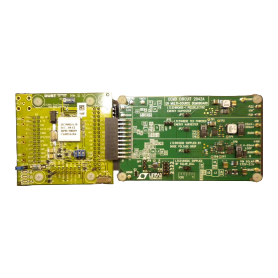
Energy Harvesting (EH) Multisource
DC2042A Connected to DC9003A-B Dust Mote (Top View)
DEMO MANUAL DC2042A
LTC3588-1/LTC3108/LTC3105/
LTC3459/LTC2935-2/LTC2935-4
In addition, many turrets are provided and one transducer
header is available to make it easy to connect transducers
to the board.
The board contains multiple jumpers that allow the board
to be configured in various ways. The standard build for
the board has three jumpers installed out of the possible
10 jumpers. The board is very customizable to the end
users' needs. This compatibility makes it a perfect evalu-
ation tool for any low power energy harvesting system
Please refer to the individual data sheets for the opera-
tion of each power management circuit. The application
section of this demo manual describes the system level
functionality of this board and the various ways it can be
used in early design prototyping.
Design files for this circuit board are available at
http://www.linear.com/demo
L, LT, LTC, LTM, Linear Technology and the Linear logo are registered trademarks of Linear
Technology Corporation. All other trademarks are the property of their respective owners.
Demo Board
dc2042af
1
Advertisement

Related Manuals for Linear Technology DC2042A


Summary of Contents for Linear Technology DC2042A
- Page 1 The board supports the following interconnects: L, LT, LTC, LTM, Linear Technology and the Linear logo are registered trademarks of Linear Technology Corporation. All other trademarks are the property of their respective owners. • Direct connection with the Dust Mote demo boards, the DC9003A-B Mote on a chip or the DC9003A-A Manager on a chip.
-
Page 2: Quick Start Procedure
DEMO MANUAL DC2042A DESCRIPTION DC2042A Connected to DC9003A-B Dust Mote (Bottom View) QUICK START PROCEDURE J4 (Vertical Transducer Header) has a KEY in position Refer to Figures 2 through 6 for the proper measurement equipment setup and jumper settings for the following test procedure. - Page 3 DEMO MANUAL DC2042A QUICK START PROCEDURE 13. Turn off PS3 2. Configure the test equipment and jumpers as shown in Figure 2. Verify the jumper settings are as follows: 14. MOVE JP1 to JP3. Disconnect PS3 from the board and set PS4 equal to 5.0V.
- Page 4 DEMO MANUAL DC2042A QUICK START PROCEDURE Figure 2. VMCU Power Switchover Test Setup (Test Steps 2 to 5) Figure 3. Solar Circuitry Test Setup (Test Steps 6 to 9 ) Proper Measurement Equipment Setup for DC2042A Solar Circuit Testing dc2042af...
- Page 5 Figure 4. Piezoelectric Circuitry Test Setup (Test Steps 10 to 13 ) Proper Measurement Equipment Setup for DC2042A Piezoelectric Circuit Testing Figure 5. 4mA to 20mA Loop Circuitry Test Setup (Test Steps 14 to 17) Proper Measurement Equipment Setup for DC2042A 4mA to 20mA Loop Circuit Testing dc2042af...
- Page 6 DEMO MANUAL DC2042A QUICK START PROCEDURE Figure 6. TEG-Powered Circuitry Test Setup (Test Steps 18 to 22) Proper Measurement Equipment Setup for DC2042A TEG Circuit Testing dc2042af...
- Page 7 DEMO MANUAL DC2042A QUICK START PROCEDURE Figure 7a. DC2042A Top Assembly Drawing J4 VERTICAL TRANSDUCER HEADER J3 HORIZONTAL TRANSDUCER HEADER J2 DUST EH HEADER Figure 7b. DC2042A Bottom Assembly Drawings dc2042af...
-
Page 8: Jumper Functions
DEMO MANUAL DC2042A APPLICATION INFORMATION JUMPER FUNCTIONS The 100µF capacitors have a voltage coefficient of 0.47 at 5.25V. Caution: Only JP9 or JP10 may be connected JP1: Power selection jumper used to select the LTC3588-1, at any one time. Do not populate both JP9 and JP10. - Page 9 DEMO MANUAL DC2042A APPLICATION INFORMATION VIN SOLAR (E7): Input to the LTC3459, solar-powered Pin 8 (EHORBAT): Signal indicating if the battery or the circuit with maximum power point control provided by energy harvester is providing power to the system. Refer the LTC2935-4.
- Page 10 DEMO MANUAL DC2042A APPLICATION INFORMATION LTC3588-1: PIEZOELECTRIC ENERGY HARVESTING The optional components R1, R4, Q1 and C5 shown on POWER SUPPLY (VIBRATION OR HIGH IMPEDANCE the schematic are not populated for a standard assembly. AC SOURCE) The function of R1, R4, Q1 and C5 is to generate a short...
- Page 11 DEMO MANUAL DC2042A APPLICATION INFORMATION LTC3108: TEG-POWERED ENERGY HARVESTER needs to be changed so the turn-on threshold is below the PGOOD_LTC3108 turn-on threshold of 3.053V. For The LTC3108 TEG-powered energy harvester is selected example, by changing R36 to a 0Ω jumper and R5 to by installing the power selection jumper JP2.
- Page 12 PGOOD signal is high (>1.4V). Again a resistor divider is to step through the program sequence or as an indication generated by the pull-up resistor R23 on the DC2042A of when it can perform energy intensive functions, such as and R4, the pull-down resistor on the DC9003A-A or a sensor read or a wireless transmission and/or receive, DC9003A-B.
- Page 13 DEMO MANUAL DC2042A APPLICATION INFORMATION Diode D4 is an optional component used to “Diode-OR” for customization of the PGOOD thresholds and hysteresis multiple energy harvesting sources together. This diode window. By using R14, R35 and R36 the inputs can be...
- Page 14 DEMO MANUAL DC2042A APPLICATION INFORMATION Figure 11: Detailed Schematic of LTC3459 Supplied by a Solar Cell Figure 12: Detailed Schematic of PGOOD_LTC3459 Circuit Using LTC2935-2 dc2042af...
- Page 15 2) Probe Signals: DC2042A EH multisource demo board connected to a a) GREEN = VMCU on the EH Board (J2-1 on DC2042A) DC9003A-B Dust Mote, all powered by a G24i, Indy4100 solar panel and a CR2032 primary cell lithium-ion bat- b) YELLOW = PGOOD_LTC3459 (J2-4 on DC2042A) tery.
- Page 16 DEMO MANUAL DC2042A APPLICATION INFORMATION Figure 14. DC2042A LTC3459 Operation at 100 lux with Indy4100 Solar Panel Figure 15: DC2042A LTC3459 Operation at 210 lux with Indy4100 Solar Panel dc2042af...
- Page 17 DEMO MANUAL DC2042A APPLICATION INFORMATION Figure 16. DC2042A LTC3459 Operation at 275 lux with Indy4100 Solar Panel Figure 17. DC2042A LTC3459 Operation at 300 lux with Indy4100 Solar Panel dc2042af...
-
Page 18: Parts List
DEMO MANUAL DC2042A PARTS LIST ITEM REFERENCE PART DESCRIPTION MANUFACTURER/PART NUMBER Required Circuit Components C1, C7, C18 CAP, CHIP, X5R, 1µF, 10%, 6.3V, 0402 TDK, C1005X5R0J105KT C2, C10, C24, C26 CAP, CHIP, X5R, 100µF, 20%, 10V, 1210 TAIYO YUDEN, LMK325ABJ107MM... - Page 19 DEMO MANUAL DC2042A PARTS LIST ITEM REFERENCE PART DESCRIPTION MANUFACTURER/PART NUMBER IC,ULTRALOW VOLTAGE STEP-UP CONVERTER AND POWER LINEAR TECH., LTC3108EDE MANAGER, DFN 3mm x 4mm IC, 400mA STEP-UP DC/DC CONVERTER WITH MPPC AND LINEAR TECH., LTC3105EDD 250mV START-UP, DFN 3mm x 3mm IC, 10V MICROPOWER SYNC BOOST CONVERTER, LINEAR TECH., LTC3459EDC...
-
Page 20: Schematic Diagram
DEMO MANUAL DC2042A SCHEMATIC DIAGRAM dc2042af... - Page 21 Information furnished by Linear Technology Corporation is believed to be accurate and reliable. However, no responsibility is assumed for its use. Linear Technology Corporation makes no representa- tion that the interconnection of its circuits as described herein will not infringe on existing patent rights.
- Page 22 Linear Technology Corporation (LTC) provides the enclosed product(s) under the following AS IS conditions: This demonstration board (DEMO BOARD) kit being sold or provided by Linear Technology is intended for use for ENGINEERING DEVELOPMENT OR EVALUATION PURPOSES ONLY and is not provided by LTC for commercial use. As such, the DEMO BOARD herein may not be complete in terms of required design-, marketing-, and/or manufacturing-related protective considerations, including but not limited to product safety measures typically found in finished commercial goods.
Need help?
Do you have a question about the DC2042A and is the answer not in the manual?
Questions and answers