Table of Contents
Advertisement
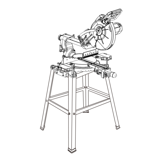
Operator's Manual
10 IN. SLIDING COMPOUND MITER SAW
WITH STAND
Model No. 137.418000
CAUTION:
Before using this Miter Saw,
read this manual and follow
all its Safety Rules and
Operating Instructions
For Technical Support and
Missing or Damaged Parts
1-800-843-1682
Sears Brands Management Corporation Hoffman Estates, IL 60179 USA
See the full line of Craftsman
Click on the Craftsman Club
Part No. 137418000001
products at craftsman.com
®
link and join today!
®
1
Safety Instructions
●
Assembly
●
Operation
●
Maintenance
●
Parts List
●
Espanol p. 57
●
Sears Parts &
Repair Center
1-888-331-4569
Printed in China
Advertisement
Table of Contents

Subscribe to Our Youtube Channel
Related Manuals for Craftsman 137.418000


Summary of Contents for Craftsman 137.418000
- Page 1 Sears Parts & Missing or Damaged Parts Repair Center 1-800-843-1682 1-888-331-4569 Sears Brands Management Corporation Hoffman Estates, IL 60179 USA See the full line of Craftsman products at craftsman.com ® Click on the Craftsman Club link and join today! ®...
-
Page 2: Table Of Contents
For 90 DAY commercial and rental terms, see the Craftsman warranty web page. This warranty gives you specific legal rights, and you may also have other rights which vary from state to state. -
Page 3: Product Specifications
PRODUCT SPECIFICATIONS MOTOR: Power Source ........120V AC, 60 Hz, 15 Amp Speed ............ 4800 RPM (No load) Electric Brake ........Yes Double Insulated ........Yes BLADE: Diameter ..........10 in. Arbor Hole ..........5/8 in. MITER SAW: Miter Detent Stops ......... 0°, 15°, 22.5°, 31.6°, 45° Right & Left Bevel Positive Stops ...... -
Page 4: Symbols
SYMBOLS WARNING ICONS Your power tool and its Operator’s Manual may contain “WARNING ICONS” (a picture symbol intended to alert you to, and/or instruct you how to avoid, a potentially hazardous condition). Understanding and heeding these symbols will help you operate your tool better and safer. Shown below are some of the symbols you may see. -
Page 5: Power Tool Safety
POWER TOOL SAFETY 7. MAKE WORKSHOP CHILD GENERAL SAFETY INSTRUCTIONS BEFORE USING THIS POWER TOOL PROOF with padlocks, master switches or by removing starter Safety is a combination of common keys. sense, staying alert and knowing how to use your power tool. 8. - Page 6 ALWAYS WEAR EYE 17. USE RECOMMENDED PROTECTION. Any power ACCESSORIES. Consult tool can throw foreign this Operator’s Manual for objects into the eyes and could recommended accessories. cause permanent eye damage. The use of improper accessories ALWAYS wear Safety Goggles (not may cause risk of injury to yourself glasses) that comply with ANSI or others.
- Page 7 22. MAINTAIN TOOLS WITH CARE. Keep tools sharp and clean for best and safest performance. Follow instructions for lubricating and changing accessories. 23. DO NOT use power tool in presence of flammable liquids or gases. 24. DO NOT operate the tool if you are under the influence of any drugs, alcohol or medicationn that could affect your ability to use the tool...
-
Page 8: Sliding Compound Miter Saw Safety
SLIDING COMPOUND MITER SAW SAFETY SPECIFIC SAFETY INSTRUCTIONS 10. USE only blade collars specified for FOR THIS COMPOUND MITER SAW your saw. 1. DO NOT operate the miter saw 11. NEVER use blades larger in until it is completely assembled diameter than 10 inches. - Page 9 22. NEVER cut small pieces. If the immediately. Be alert at all times workpiece being cut would cause - especially during repetitive, your hand or fingers to be within monotonous operations. Don’t be 7-1/2 in. of the saw blade the lulled into carelessness due to a workpiece is too small.
-
Page 10: Electrical Requirements And Safety
ELECTRICAL REQUIREMENTS AND SAFETY POWER SUPPLY AND MOTOR To reduce the risk of electrical shock, SPECIFICATIONS this saw has a polarized plug (one The AC motor used in this saw is blade is wider than the other). This plug a universal, nonreversible type. will fit in a polarized outlet only one See “MOTOR”... - Page 11 3. If the tool suddenly stalls while Be sure your extension cord is cutting wood, release the trigger properly wired and in good condition. switch, unplug the tool, and free the Always replace a damaged extension blade from the wood. The saw may cord or have it repaired by a qualified now be started and the cut finished.
-
Page 12: Accessories And Attachments
ACCESSORIES AND ATTACHMENTS RECOMMENDED ACCESSORIES always visually examine the blade and tips for bent blade, cracks, WARNING breakage, missing or loose tips, or ● Use only accessories recommended other damage. Do not use if damage for this miter saw. Follow is suspected. -
Page 13: Tools Needed For Assembly
TOOLS NEEDED FOR ASSEMBLY Not supplied Supplied Adjustable Wrench Phillips Screwdriver Blade Wrench 4 mm & 6 mm Slotted Screwdriver Hex Wrench Combination Square Straight Edge COMBINATION SQUARE MUST BE TRUE Should not gap or overlap when square is flipped over (see dotted figure). Straight edge or a 3/4 in. -
Page 14: Carton Contents
CARTON CONTENTS UNPACKING YOUR MITER SAW 3. Separate all parts from the packing material. Check each one with the WARNING illustration to make certain all items are accounted for before discarding To avoid injury from unexpected any packing material. starting or electrical shock, do not plug the power cord into a source WARNING of power during unpacking and... - Page 15 UNPACKING YOUR STAND This product requires assembly. 1. Remove the stand and all parts from the carton. 2. Place the stand on the ground. 3. Separate all parts from the packing material. Check each one with the illustration below to make certain all items are accounted for before discarding any packing material.
-
Page 16: Know Your Sliding Compound Miter Saw
KNOW YOUR SLIDING COMPOUND MITER SAW Trigger Switch Handle Laser Vertical Adjustment Knob Laser Horizontal Adjustment Knob Laser Trac ® Upper Blade Guard Laser Guide Motor Bevel Detent Pin Lower Blade Mounting Hole Guard Table Insert Miter Handle Table Base Left Extension Table Exhaust port Carrying Handle... -
Page 17: Glossary Of Terms
GLOSSARY OF TERMS AMPERAGE (AMPS) – A measure EYE PROTECTION – Googles or of the flow of electric current. Higher spectacles intended to protect your ratings generally means the tool is eyes. Eye protection should meet the suited for heavier use. requirements of ANSI Z.87.1 (USA) or CSA Z94.3-M88 (Canada). - Page 18 ON/OFF TRIGGER SWITCH – To start KERF – The width of a saw cut, the tool, squeeze the trigger. Release determined by the thickness and set of the trigger to turn off the miter saw. the blade. POSITIVE STOP LOCKING LEVER – KICKBACK –...
-
Page 19: Assembly
ASSEMBLY detents (12) in stand leg align with WARNING support bracket. Then, tighten all To avoid injury, do not connect this bolts using a 13mm wrench. miter saw to the power source until NOTE: Stand should not rock after it is completely assembled and all bolts are tightened. - Page 20 CUTTING HEAD (FIG. B) INSTALLING THE MITER HANDLE (FIG. C) Raising 1. Thread the miter handle (1) into the 1. Push down slightly on the trigger hole (2) located at the front of the switch handle (1). miter table. 2. Pull out the hold-down latch (2). 3.
- Page 21 Fig. D Fig. F INSTALLING THE HOLD-DOWN UNLOCKING THE SLIDE CARRIAGE CLAMP (FIG. E, F) (FIG. G) 1. Loosen the knob (1) from the rear After removing the saw from the carton, side of the saw base. loosen the slide carriage lock knob (1), 2.
- Page 22 REMOVING AND INSTALLING THE Fig. H BLADE WARNING ● To avoid injury from an accidental start, make sure the switch is in the OFF position and the plug is not connected to the power source outlet. ● Only use a 10 in. diameter blade. NOTE: The miter saw comes with the saw blade already installed.
- Page 23 NOTE: Pay attention to the pieces 2. Place the blade wrench on the arbor removed, noting their position and bolt (4). (Fig. H) direction they face. Wipe the blade 3. Press the arbor lock button (5), collars clean of any sawdust before holding it in firmly while turning the installing a new blade.
- Page 24 SAW BLADE WRENCH (FIG. K) 2. To install, reposition the table For convenient storage and prevention insert (2), install the six screws (1) of loss, there is a slot (1) in the right and tighten. side of the carry handle (2) for storing 3.
- Page 25 ● Never carry the miter saw by NOTE: The referenced mounting the power cord or by the trigger hardware is not included with this tool. switch handle. Carrying the tool Bolts, nuts, washers and screws must by the power cord could cause be purchased separately.
-
Page 26: Adjustments
ADJUSTMENTS BEVEL STOP ADJUSTMENT Fig. O WARNING To avoid injury from an accidental start, make sure the switch is in the OFF position and the plug is not connected to the power source. 90° (0°) Bevel Adjustment (Fig. O) 1. Loosen bevel lock knob (1) and tilt the cutting arm completely to the right. - Page 27 45° Bevel Adjustment (Fig. Q) 3. Using a combination square, check 1. Loosen the bevel lock knob (1) and to see if the blade angle is 33.9° to tilt the cutting head completely to the table. the left. 4. If the blade is not at 33.9° to the 2.
- Page 28 2. Move the turntable while lifting up ADJUSTING FENCE SQUARENESS on the positive stop lock lever (2) (FIG. T) to align the pointer (3) to the desired 1. Lower the cutting arm and lock in degree measurement. position. 3. If the desired angle is one of the 2.
- Page 29 SETTING CUTTING DEPTH (FIG. U) control arm throat or any part of the The depth of cut can be preset for even base or table. If the maximum depth and repetitive shallow cuts. needs readjusting: 1. Adjust the cutting head down (See 1.
- Page 30 TURNING LASER TRAC ON (FIG. W) AVOID DIRECT EYE CONTACT ® 1. To turn laser on, press on/off rocker (FIG. X) switch (1) to “ON” position. WARNING 2. To turn laser off, press on/off rocker ● Laser radiated when Laser Trac ®...
- Page 31 ● CAUTION: The use of optical A. Checking Laser Line Alignment instruments with this product will (Fig. Y, AA) increase eye hazard. 1. Set the saw to a 0° miter and 0° ● WARNING: Do not attempt to bevel setting. repair or disassemble the laser.
- Page 32 7. Looking at the top of the board, Fig. Y TOP VIEW if the laser line is not parallel to Laser line the “pattern line” please follow the instructions listed below under Top Cutting Blade Line paragraph. line B. Adjusting the Position of the Laser Line (Fig.
-
Page 33: Operation
OPERATION SAFETY INSTRUCTIONS FOR BASIC adjustments, including set-up and SAW OPERATION blade changes. ● Compare the direction of rotation BEFORE USING THE MITER SAW arrow on the guard to the direction arrow on the blade. The blade teeth WARNING should always point downward at To avoid mistakes that could cause the front of the saw. - Page 34 ● Remove adjusting wrench from the ● Plan ahead to protect your eyes, tool before turning it on. hands, face and ears. ● To avoid injury from jams, slips, ● Know your miter saw. Read and or thrown pieces, use only understand this Operator’s Manual recommended accessories.
- Page 35 DRESS FOR SAFETY Never cut freehand: ● Brace your workpiece firmly against Any power tool can throw foreign objects into the eyes. the fence and table stop so it will This can result in permanent eye not rock or twist during the cut. ●...
- Page 36 ● When cutting odd shaped MAKING A BASIC CUT workpieces, plan your work so WARNING it will not bind in the blade and Body and Hand Position (Fig. CC) cause possible injury. Molding, for Never place hands near example, must lie flat or be held by the cutting area.
- Page 37 ● If the blade does not stop within TURNING THE SAW ON (FIG. DD) 6 seconds, unplug the saw Squeeze the trigger switch (1) to turn and follow the instructions in the miter saw ON. Release the trigger TROUBLESHOOTING GUIDE switch to turn the saw OFF.
- Page 38 SLIDING CARRIAGE SYSTEM remove small pieces of material (FIG. EE) from the table cavity. WARNING MITER CUT (FIG. FF) To reduce the risk of injury, return 1. When a miter cut is required, unlock carriage to the full rear position after the miter table by turning the miter each crosscut operation.
- Page 39 2. Loosen the bevel lock handle (2). BEVEL CUT (FIG. GG) 3. Rotate the cutting head until the 1. When a bevel cut is required, bevel detent pin stops the bevel loosen the bevel lock handle (1) by angle at 33.9° on the bevel scale. turning it clockwise.
- Page 40 4. Turn the Laser Trac on and ® Fig. II position the workpiece on the table for prealignment of your cut. 5. Grasp the switch handle (2) and pull the carriage forward until the center of the saw blade is over the front of the workpiece (3).
- Page 41 The table insert may be removed for 2. Lower the cutting head so the tip of this purpose, but always reattach table the blade touches the top surface of insert prior to performing a cutting the workpiece at the marked line. operation.
- Page 42 Fig. MM Fig. NN Blade Slot AUXILIARY WOOD FENCE (FIG. NN) CUTTING BASE MOLDING (FIG. OO) When making multiple or repetitive Base moldings and many other cuts that result in cut-off pieces of one moldings can be cut on a compound inch or less, it is possible for the saw miter saw.
- Page 43 Fig. OO Fig. PP Workpiece Workpiece Workpiece Miter saw table Miter saw table Miter saw table Miter at 45°, bevel at 0° Miter at 0°, bevel at 45° NOTE: Always perform a dry run cut Fig. QQ so you can determine if the operation Settings for standard crown molding being attempted is possible before lying flat on compound miter saw...
- Page 44 Bevel/Miter Settings NOTE: The chart on next page references a compound cut for crown molding ONLY WHEN THE ANGLE BETWEEN THE WALLS EQUALS 90°. BEVEL MITER TYPE OF CUT SETTING SETTING Inside corner-Left side 33.9° 31.6° Right 1. Position top of molding against fence. 2.
- Page 45 CROWN MOLDING CHART Compound Miter Saw Miter and Bevel Angle Settings Wall to Crown Molding Angle 52/38° Crown Molding 45/45° Crown Molding 52/38° Crown Molding 45/45° Crown Molding Angle Angle Miter Bevel Miter Bevel Miter Bevel Miter Bevel Between Between Setting Setting Setting...
-
Page 46: Maintenance
MAINTENANCE MAINTENANCE replace. Replace for the other side. To reassemble, reverse the procedure. DANGER The ears on the metal end of the Never put lubricants on the blade assembly go in the same hole the while it is spinning. carbon part fits into. - Page 47 Lubricate the following as necessary: WARNING ● When cleaning the lower guard, Chop pivot: Apply light machine oil to unplug the saw from the power points indicated in illustration. source receptacle to avoid unexpected start-up. Central pivot of plastic guard: Use ●...
-
Page 48: Troubleshooting Guide
TROUBLESHOOTING GUIDE WARNING To avoid injury from accidental starting, always turn switch OFF and unplug the tool before moving, replacing the blade or making adjustments. TROUBLESHOOTING GUIDE - MOTOR SUGGESTED CORRECTIVE PROBLEM PROBLEM CAUSE ACTION Brake does not 1. Motor brushes not sealed 1. - Page 49 TROUBLESHOOTING GUIDE - SAW OPERATION SUGGESTED CORRECTIVE PROBLEM PROBLEM CAUSE ACTION Blade hits table. 1. Misalignment. 1. See ADJUSTMENT - Cutting Arm Travel section. Angle of cut not 1. Miter table unlocked. 1. See OPERATION - Miter Angle accurate. Can 2.
-
Page 50: Parts List
MODEL NO. 137.418000 WARNING When servicing use only CRAFTSMAN replacement parts. Use of any other parts many create a HAZARD or cause product damage. Any attempt to repair or replace electrical parts on this Miter Saw may create a HAZARD unless repair is done by a qualified service technician. - Page 51 10 IN. SLIDING COMPOUND MITER SAW MODEL NO. 137.418000 PARTS LIST FOR MITER SAW B I.D. NO. Description Size Q’ty I.D. NO. Description Size Q’ty 2WPX POWER CABLE 3HK9 FLAT WASHER 3/8*29/32-1/8 2WUT TRADEMARK LABEL 3HML KNOB 2X6M CAUTION STICKER 3HMY HEX.SOCKET HD.CAP...
- Page 52 10 IN. SLIDING COMPOUND MITER SAW MODEL NO. 137.418000 SCHEMATIC 3QLG 2K96 290M 3HMY...
- Page 53 10 IN. SLIDING COMPOUND MITER SAW MODEL NO. 137.418000 PARTS LIST AND SCHEMATIC FOR MOTOR I.D. NO. Description Size Q’ty 0HX9 NEEDLE BEARING 0JCD SPRING PIN 0JX2 HEX. SOC SET SCREW M5*0.8-6 0K43 CR.RE. PAN HD. SCREW & WASHER M5*0.8-16 0K44 CR.RE.
- Page 54 10 IN. SLIDING COMPOUND MITER SAW MODEL NO. 137.418000 PARTS LIST AND SCHEMATIC FOR STAND I.D. NO. Description Size Q’ty 093B FOOT PAD 0J4F FLAT WASHER φ8*16-2.5 0KRR SERRATED TOOTHED HEXAGON FLANGE NUT M8*1.25 T=7.5 22XY STAND LEG 23AC CR. RE. PAN HD. SCREW M8*1.25-40...
-
Page 55: Repair Protection Agreements
REPAIR PROTECTION AGREEMENTS Congratulations on making a smart purchase. Your new Craftsman product ® is designed and manufactured for years of dependable operation. But like all products, it may require repair from time to time. That’s when having a Repair Protection Agreement can save you money and aggravation. - Page 56 NOTES...
Need help?
Do you have a question about the 137.418000 and is the answer not in the manual?
Questions and answers