Table of Contents
Advertisement
Quick Links
Advertisement
Table of Contents

Related Manuals for Quatech SSP-200


Summary of Contents for Quatech SSP-200
- Page 1 SSP-200/300 Single Channel RS-422/485 PCMCIA Asynchronous Adapter for PCMCIA Card Standard compatible machines User's Manual INTERFACE CARDS FOR IBM PC/AT AND PS/2 QUATECH, INC. 5675 Hudson Industrial Parkway Hudson, Ohio 44236 TEL: (330) 434-3154 FAX: (330) 434-1409 www.quatech.com...
-
Page 2: Warranty Information
No representation is made regarding the suitability of this product for any particular purpose. Quatech Inc. reserves the right to edit or append to this document or the product(s) to which it refers at any time and without notice. -
Page 3: Declaration Of Conformity
Application of Council Directive: Standards to which Conformity is Declared: Type of Equipment: Equipment Class: Product Name: Model Number : SSP-200/300 (Rev. I and later) User's Manual Quatech, Inc. 662 Wolf Ledges Parkway Akron, OH 44311 (USA) 89/336/EEC * EN50081-1 (EN55022) * EN50082-1 (IEC 801-2, IEC 801-3, &... -
Page 4: Table Of Contents
............Installing a SSP-200/300 Under Windows 2000 ....... -
Page 5: Introduction
AUXOUT and CTS received through AUXIN. The role of AUXOUT and AUXIN can be set when the SSP-200/300 is configured. The SSP-200/300 may be configured to operate in either the Full Duplex or Half Duplex mode; the SSP-200/300 may be configured so that the output drivers are always enabled, RTS or DTR enable the output drivers, or the output drivers are automatically enabled only when data is being transmitted. - Page 6 This page intentionally left blank. SSP-200/300 (Rev. I and later) User's Manual...
-
Page 7: Dos/Windows 3
2. DOS/Windows 3.x Two configuration software programs are provided with the SSP-200/300: a Client Driver, and a card Enabler. Both of these programs are executed from DOS (before entering Windows) and allow operation of the SSP-200/300 in both the DOS and Windows 3.x environments. For optimal operation, however, the Client Driver is the preferred method of installation and configuration. -
Page 8: Ssp-200/300 Client Driver For Dos
2.1 SSP-200/300 Client Driver for DOS In order to use the SSP-200/300 Client Driver, the system must be configured with Card and Socket Services software. SSP-200/300 but is available from Quatech. IMPORTANT: Some versions of Card and Socket Services dated before 1993 do not support general purpose I/O cards. -
Page 9: Command Line Options
2.1.2 Command Line Options The SSP-200/300 Client Driver accepts up to eight command line arguments from the user to determine the configuration of theSSP-200/300. If any arguments are provided, the Client Driver will attempt to configure any SSP-200/300s with the options specified in the order they are entered on the command line. - Page 10 In example 2, a single command line argument is provided. The Client Driver will attempt to configure a SSP-200/300 inserted into any socket with a base address of 290H and IRQ 11. If address 290H or IRQ 11 is unavailable, the SSP-200/300 will not be configured. If the Client Driver can successfully configure the SSP-200/300unit, the RS-422/485 output drivers will always be enabled, and RTS-CTS modem control handshaking will be disabled.
- Page 11 In example 5, three command line arguments are provided. The Client Driver will first attempt to configure a SSP-200/300 inserted into any socket with a base address of 300H and IRQ 5. If address 300H or IRQ 5 is unavailable, the Client Driver will proceed to the second command line argument and attempt to configure the card with a base address assigned by Card and Socket Services and IRQ 10.
-
Page 12: Common Problems
SSP-200/300 is to be installed. In this example, the Client Driver will attempt to configure a SSP-200/300 inserted into socket 0 with a base address of 300H and IRQ 5. If the SSP-200/300 is inserted into socket 1, the Client Driver will attempt to configure it with base address 340H and IRQ 10. -
Page 13: Ssp-200/300 Enabler For Dos
Some versions of Card and Socket Services dated before 1993 do not support general purpose I/O cards. If after careful installation of the Client Driver the SSP-200/300 does not configure or operate properly, an updated version of Card and Socket Services may be required. Card and Socket Services software is available from Quatech. -
Page 14: Command Line Options
Iirq specifies the interrupt level (IRQ) of the SSP-200/300 in decimal. irq must be one of the following values: 3, 4, 5, 7, 9, 10, 11, 12, 14, 15, or 0 if no IRQ is desired. This option is required if the 'R' option is not used. - Page 15 See the Hardware Information section for more information . Before removing a SSP-200/300 from its PCMCIA socket, the Enabler should be executed to free the system resources allocated when the card was installed. For this operation the Enabler...
- Page 16 2.2.1.2 Example 2 SSP231EN.EXE (s0,b300,i5) In example 2, the Enabler will configure the SSP-200/300 in socket 0 with a base address of 300H and IRQ 5 using a configuration memory window at segment D000. The SSP-200/300 unit's RS-422/485 output drivers will always be enabled, and RTS-CTS modem control handshaking will be disabled.
-
Page 17: Common Problems
2.2.1.6 Example 6 SSP231EN.EXE (s0,b300,i5,r) In example 6, the Enabler will release the configuration used by the SSP-200/300 in socket 0 using a configuration memory window at segment D000. The base address and IRQ parameters are ignored and may be omitted. - Page 18 This page intentionally left blank. SSP-200/300 (Rev. I and later) User's Manual...
-
Page 19: Windows 95/98/Millennium (Me)
SSP-200/300 card. Click the "Search for the best driver for your device" option button. Click "NEXT" to continue. 4. An "Install from Disk" dialog box should appear. Insert the Quatech COM CD file, select the correct drive letter and path, and click "OK". Windows 95/98/ME will browse the path for the aforementioned files. -
Page 20: Viewing Resource Settings With Device Manager
SSP-200/300 is Quatech SSP-200/300: RS-422/RS-485 Serial Port PC Card. 4. Open the Properties dialog for the SSP-200/300 device, then click the Resources tab to view the Input/Output Range and Interrupt Request resource allocations. 5. Double click the hardware class Ports (Com and LPT). The Quatech Communications Port listed in this class is a “child device”... - Page 21 (auto-toggle). Both RTS and DTR are controlled through the Modem Control Register of the 16750. When the Use Automatic Settings check box is enabled Windows 95/98/ME will attempt to configure the SSP-200/300 in the order listed in the Basic Configurations table. Basic...
-
Page 22: Frequently Asked Questions
A problem noted on some systems is after a basic configuration has been manually selected the basic configurations list for the SSP-200/300 is no longer available. The solution to this problem is to check the “Use Automatic Settings” box and allow Windows 95/98/ME to reconfigure the SSP-200/300 card. - Page 23 Base I/O Address Resource Modification Not Allowed: The SSP-200/300 is configured to allow only a fixed number of base I/O addresses. To change the I/O address resources for the SSP-200/300 select another “Basic Configuration.” Refer to the Basic Configurations table for a list of the availabe I/O address resources for the SSP-200/300...
- Page 24 This page intentionally left blank. SSP-200/300 (Rev. I and later) User's Manual...
-
Page 25: Installing A Ssp-200/300 Under Windows 2000
4 Windows 2000 To allow easy configuration of the SSP-200/300, an Windows 2000 "INF" configuration file has been written for the hardware. This configuration file supports the SSP-200/300 in both addressing modes: block mode and “com” mode. Additionally, the RTS-CTS modem control handshake option and the RS-422/485 output driver enable option for full and half duplex operation is supported. - Page 26 4. Double click ‘Serial Port Adapters’ 5. Double click ‘Drivers’ SSP-200/300 (Rev. I and later) User's Manual...
- Page 27 6. Double click on ‘Windows 2000, XP, for PCI, PCMCIA, ISA’ 7. Click on ‘qserbrd’ and select open Windows 2000...
-
Page 28: Ssp-200/300 Resource Settings In Windows 2000
Click on the Hardware tab then click on the Device Manager. Consult Windows 2000 on-line help Windows 2000 handles the SSP-200/300 as a "parent/child device". v The SSP-200/300 is the "parent device" and is listed under the hardware class Quatech Multiport Serial Devices in the device manager. -
Page 29: Viewing Resource Settings With Device Manager
SSP-200/300 is Quatech SSP-200/300 PCMCIA RS-422/RS-485 Serial Adapter. 4. Open the Properties dialog for the SSP-200/300 device, then click the Resources tab to view the Input/Output Range and Interrupt Request resource allocations. Examine and remember the Input/Output Range, then close the properties window. -
Page 30: Changing Resource Settings With Device Manager
3. The SSP-200/300 “parent device” belongs to this hardware class. The device name for the SSP-200/300 is Quatech SSP-200/300 PCMCIA RS-422/RS-485 Serial Adapter. 4. Open the Properties dialog for the SSP-200/300 device, then click the Advanced tab to view the clock rate settings. SSP-200/300 (Rev. I and later) User's Manual... - Page 31 Windows 2000...
- Page 32 The baud rate the port runs at will always be eight times the rate requested by the application. This mode is useful for legacy applications which cannot request baud rates over 115.200. SSP-200/300 (Rev. I and later) User's Manual...
- Page 33 Windows 2000 4-10...
- Page 34 Used in two-wire communication Hardware automatically enables the transmitters when transmitting. Transmitters will turn off three bit-times after the last stop bit of the last character, regardless of baud rate. Used in two-wire communication. SSP-200/300 (Rev. I and later) User's Manual...
- Page 35 Basic Auxiliary Configuration Connections** 0000* Loopback 0001* Loopback 0002* Loopback 0003* Loopback 0004 Loopback 0005 Loopback 0006 Loopback 0007 Loopback 0008 Loopback 0009 Handshaking 0010 Clocking 0011 Loopback 0012 Loopback 0013 Loopback 0014 Handshaking 0015 Clocking 0016 Handshaking 0017 Clocking 0018 Handshaking 0019...
- Page 36 DTR Controlled DTR Controlled Auto Toggle Auto Toggle RTS Controlled RTS Controlled DTR Controlled DTR Controlled Memory Always Enabled Mapped SSP-200/300 (Rev. I and later) User's Manual Normal Normal Normal Scratch Pad Scratch Pad Normal Scratch Pad Normal Scratch Pad Normal...
- Page 37 Do not select a value that causes a conflict with any other installed hardware. 10. If any changes have been made to the SSP-200/300’s configuration the card will automatically be reconfigured to the new resources specified. Any time a PCMCIA card of this type is inserted Windows 2000 will attempt to configure the card at these resource settings.
- Page 38 This page intentionally left blank. SSP-200/300 (Rev. I and later) User's Manual...
-
Page 39: Windows Nt
5 Windows NT 5.1 Installing SSP-200/300 To allow easy configuration of the SSP-200/300 the Quatech Device Manager for Windows NT has been written for the hardware. This configuration utility supports the SSP-200/300 only in block addressing mode. To begin the installation, open Windows Explorer and search for the ‘Setup.exe’ command to install the Quatech Device Manager. - Page 40 1. Locate and double click the Quatech Device Manager icon on the desktop Device Manager Icon on Desktop SSP-200/300 (Rev. I and later) User's Manual...
- Page 41 2. Click the ‘Add’ button at the bottom of the Quatech Device Manager Window 3. Follow the steps for the ‘Add Quatech Hardware Wizard’. Windows NT...
- Page 42 PCMCIA Card and re-boot the computer. Additional help is available online The SSP-200/300 PC Card should now be configured. In the future, Windows NT will automatically recognize and configure the SSP-200/300. Note: Windows NT does not support ‘Plug and Play’ for PCMCIA cards. The PCMCIA Card must be inserted prior to starting Windows NT and can not be removed and reinserted while Windows NT is running.
-
Page 43: Hardware Information
6. Hardware Information 6.1 Auxiliary Channel Configuration An auxiliary channel is provided which allows for handshaking between the SSP-200/300 port and a peripheral device. This auxiliary channel may be configured in one of two ways: v RTS-CTS handshake enabled. v handshaking is disabled. -
Page 44: Auxiliary Channel: Handshaking Disabled
6.1.2 Auxiliary Channel: Handshaking Disabled. The SSP-200/300 ports may be configured so that the RTS-CTS handshake is disabled. This is the default configuration. In this configuration, RTS and CTS from the 16C750 UART will be looped back to each other. In addition, the auxiliary output and input signals will be looped back to each other. -
Page 45: Half Duplex Operation
6.2 Half Duplex Operation The SSP-200/300’s ports may be configured for either full duplex or half duplex operation. By default, the RS-422/485 ports are configured for full duplex operation with the RS-422/485 output drivers always enabled. In half duplex mode, the RS-422/485 transmitter may be enabled and disabled via the RTS (request to send) or DTR (data terminal ready) signals. - Page 46 Selection of half duplex mode operation is dependent upon the configuration software and/or the operating system used. Each of these, however, ultimately control the half duplex mode by accessing the PCMCIA Configuration Register on the SSP-200/300. CAUTION: When operating in half duplex mode, the transmitter output drivers must be disabled before receiving any information.
-
Page 47: Termination Resistors
6.3 Termination Resistors No termination resistors are provided on the SSP-200/300 ports. Both output and input signals are connected only to the external connector. Any termination which is required must be added externally. RS-422/485 Receiver RS-422/485 Receiver Recommended Termination Resistor Values... - Page 48 This page intentionally left blank. SSP-200/300 (Rev. I and later) User's Manual...
-
Page 49: External Connections
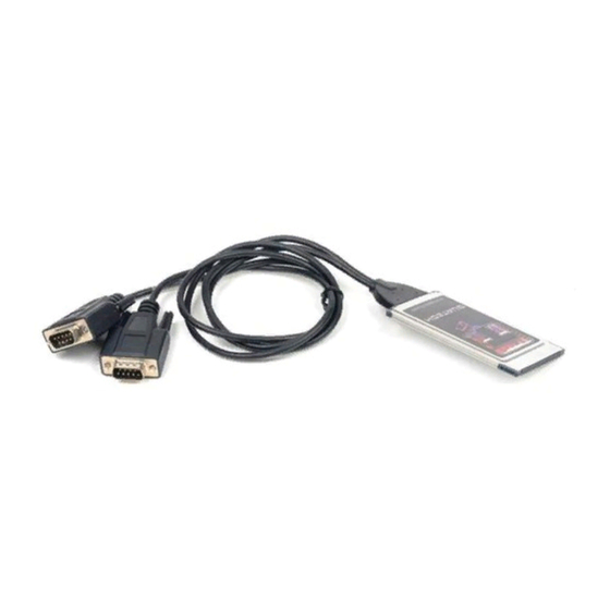
7. External Connections An adapter cable is included with the SSP-200/300 to convert the 9-pin PCMCIA output connector into a standard D-9 female connector, data terminal equipment (DTE), as shown in the figures below. Figure 0. RS-422/485 Signal Assignment. External Connections Figure 0. - Page 50 This page intentionally left blank. SSP-200/300 (Rev. I and later) User's Manual...
-
Page 51: Specifications
8. Specifications Bus Interface Physical Dimensions Maximum Baud Rate Power Requirements (maximum) Connector Specifications PCMCIA PC Card Standard 2.1 compliant Type II PCMCIA card (5mm) 921.6K +5 volts 20 mA (typical) Adapter to standard female D-9 30 mA... - Page 52 SSP-200/300 User's Manual Revision 3.12 March 2004 P/N 940-0075-312 Quatech, Inc.
Need help?
Do you have a question about the SSP-200 and is the answer not in the manual?
Questions and answers