Table of Contents
Advertisement
Quick Links
INSTRUCTION MANUAL
Installation and Operating
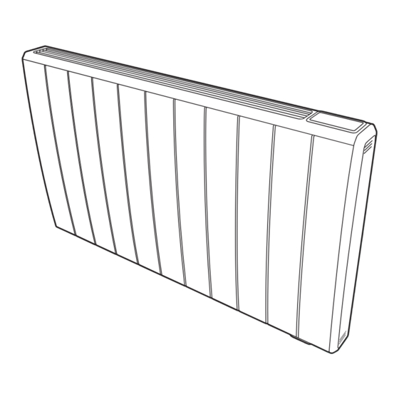
Q-Rad Electric Radiator
Models: QRAD050RF / QRAD075RF / QRAD100RF
QRAD150RF / QRAD200RF
These instructions should be read carefully
and retained for future use. Note also the
information presented on the appliance.
08/82904/0 (300001427)
ISSUE: 3
Series: G
Advertisement
Table of Contents


Need help?
Do you have a question about the Q-Rad QRAD050RF and is the answer not in the manual?
Questions and answers