Table of Contents
Advertisement
Quick Links
C
OM-00772-01
December 3, 1979
Rev. A 09-17-07
INSTALLATION, OPERATION,
AND MAINTENANCE MANUAL
WITH PARTS LIST
80 SERIES PUMP
MODEL
81 1/2E9−B
THE GORMAN-RUPP COMPANY D MANSFIELD, OHIO
www.grpumps.com
D
GORMAN-RUPP OF CANADA LIMITED
ST. THOMAS, ONTARIO, CANADA
Printed in U.S.A.
e
Copyright by the Gorman-Rupp Company
Advertisement
Table of Contents

Related Manuals for GORMAN-RUPP PUMPS 81 1/2E9-B


Summary of Contents for GORMAN-RUPP PUMPS 81 1/2E9-B
- Page 1 OM-00772-01 December 3, 1979 Rev. A 09-17-07 INSTALLATION, OPERATION, AND MAINTENANCE MANUAL WITH PARTS LIST 80 SERIES PUMP MODEL 81 1/2E9−B THE GORMAN-RUPP COMPANY D MANSFIELD, OHIO www.grpumps.com GORMAN-RUPP OF CANADA LIMITED ST. THOMAS, ONTARIO, CANADA Printed in U.S.A. Copyright by the Gorman-Rupp Company...
- Page 2 Register your new Gorman-Rupp pump online at www.grpumps.com Valid serial number and e-mail address required. RECORD YOUR PUMP MODEL AND SERIAL NUMBER Please record your pump model and serial number in the spaces provided below. Your Gorman-Rupp distributor needs this information when you require parts or service. Pump Model: Serial Number:...
-
Page 3: Table Of Contents
TABLE OF CONTENTS INTRODUCTION ..........PAGE I −... - Page 4 TABLE OF CONTENTS (continued) PUMP MAINTENANCE AND REPAIR - SECTION E ....PAGE E − 1 PERFORMANCE CURVE ........... PAGE E −...
-
Page 5: Introduction
80 SERIES OM−00772 INTRODUCTION Thank You for purchasing a Gorman-Rupp pump. The following are used to alert maintenance per- Read this manual carefully to learn how to safely sonnel to procedures which require special atten- install and operate your pump. Failure to do so tion, to those which could damage equipment, and could result in personal injury or damage to the to those which could be dangerous to personnel:... -
Page 6: Safety - Section A
80 SERIES OM−00772 SAFETY - SECTION A This information applies to 80 Series ba- ids. Do not attempt to pump liquids for sic pumps. Gorman-Rupp has no con- which the pump, driver and/or controls trol over or particular knowledge of the have not been approved, or which may power source which will be used. - Page 7 OM−00772 80 SERIES Overheated pumps can cause severe Never run this pump backwards. Be cer- burns and injuries. If overheating of the tain that rotation is correct before fully pump occurs: engaging the pump. 1. Stop the pump immediately. 2. Ventilate the area. 3.
-
Page 8: Installation − Section Bpage B
80 SERIES OM−00772 INSTALLATION − SECTION B Review all SAFETY information in Section A. configuration, and priming must be tailored to the specific application. This pump is equipped with a Since pump installations are seldom identical, this Gorman-Rupp double grease lubricated seal, section offers only general recommendations and therefore the maximum incoming pressure must practices required to inspect, position, and ar-... -
Page 9: Positioning Pump
OM−00772 80 SERIES The pump assembly can be seriously Only operate this pump in the direction in- damaged if the cables or chains used to lift dicated by the arrow on the pump body and move the unit are improperly wrapped and on the accompanying decal. -
Page 10: Gauges
80 SERIES OM−00772 Lines near the pump must be independently sup- line, and that the openings will not permit passage ported to avoid strain on the pump which could of solids larger than the solids handling capability cause excessive vibration, decreased bearing life, of the pump. -
Page 11: Discharge Lines
OM−00772 80 SERIES reduce the inlet velocity. Calculate the required NOTE submergence using the following formula based The pipe submergence required may be reduced on the increased opening size (area or diameter). by installing a standard pipe increaser fitting at the end of the suction line. -
Page 12: Alignment
80 SERIES OM−00772 of the outer ends of the coupling hub every 90 de- ALIGNMENT grees. The coupling is in alignment when the hub ends are the same distance apart at all points (see The alignment of the pump and its power source is Figure 3A). -
Page 13: V-Belt Tensioning
OM−00772 80 SERIES the belts are a matched set; unmatched sets will en both v-belt and bearing life. Under-tensioning cause accelerated belt wear. will cause belt slippage. Always keep belts free from dirt, grease, oil and other foreign material which may cause slippage. Tension Measurement Correct v-belt tension can be achieved using a v- belt tension tester and Table 1 or 2. - Page 14 80 SERIES OM−00772 er at the measured belt span. Set the small O-ring Read the force applied from the bottom of the small on the deflection force scale to zero. O-ring on the deflection force scale. Compare this force with the value shown in Table 1 or 2 and ad- Place the tension tester squarely on the belt at the just the tension accordingly.
- Page 15 OM−00772 80 SERIES Table 1. Sheave Diameter (Inches) Table 2. Sheave Diameter (Millimeters) Deflection Force (Lbs.) Deflection Force (KG.) Belt Deflection Force Belt Deflection Force Uncogged Cogged Uncogged Cogged Hy-T Belts & Torque-Flex Hy-T Belts & Torque-Flex Uncogged & Machined Uncogged &...
-
Page 16: Operation − Section C
OM−00772 80 SERIES OPERATION − SECTION C Review all SAFETY information in Section A. Add liquid to the pump casing when: 1. The pump is being put into service for the Follow the instructions on all tags, labels and first time. decals attached to the pump. -
Page 17: Operation
OM−00772 80 SERIES sprinkler heads, and any other fixtures connected from the shaft and seriously damage the to the line. When the discharge line is completely pump. filled, adjust the throttling valve to the required flow Consult the operating manual furnished with the rate. -
Page 18: Pump Vacuum Check
OM−00772 80 SERIES equipment. If backflushing is absolutely neces- Cold Weather Preservation sary, liquid pressure must be limited to 50% of the In below freezing conditions, drain the pump to maximum permissible operating pressure shown prevent damage from freezing. Also, clean out any on the pump performance curve (see Section E, solids by flushing with a hose. -
Page 19: Troubleshooting − Section D
80 SERIES OM−00772 TROUBLESHOOTING − SECTION D Review all SAFETY information in Section A. Before attempting to open or service the pump: 1. Familiarize yourself with this manual. 2. Lock out or disconnect the power source to ensure that the pump will remain inoperative. - Page 20 OM−00772 80 SERIES TROUBLE POSSIBLE CAUSE PROBABLE REMEDY Suction intake not submerged at Check installation and correct PUMP STOPS OR FAILS TO DELIVER proper level or sump too small. submergence as needed. RATED FLOW OR Replace worn or damaged parts. Impeller or other wearing parts worn PRESSURE (cont.) Check that impeller is properly...
-
Page 21: Preventive Maintenance
80 SERIES OM−00772 equipped) between regularly scheduled inspec- PREVENTIVE MAINTENANCE tions can indicate problems that can be corrected Since pump applications are seldom identical, and before system damage or catastrophic failure oc- pump wear is directly affected by such things as curs. - Page 22 OM−00772 80 SERIES PUMP MAINTENANCE AND REPAIR − SECTION E MAINTENANCE AND REPAIR OF THE WEARING PARTS OF THE PUMP WILL MAINTAIN PEAK OPERATING PERFORMANCE. STANDARD PERFORMANCE FOR PUMP MODEL 81 1/2E9−B Based on 70_ F (21 _ C) clear water at sea level Contact the Gorman-Rupp Company to verify per- formance or part numbers.
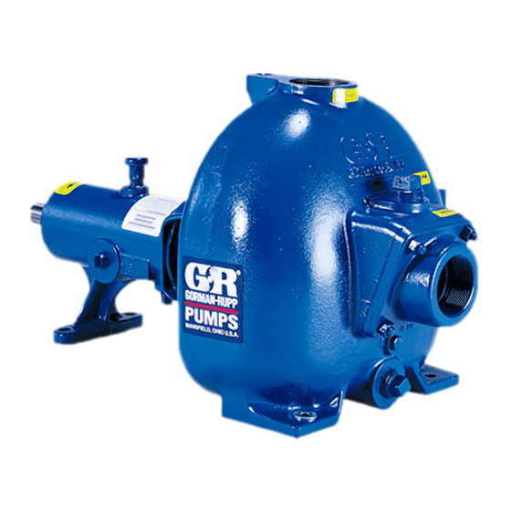
- Page 23 OM−00772 80 SERIES PARTS PAGE SECTION DRAWING Figure 1. Pump Model 81 1/2E9−B PAGE E − 2 MAINTENANCE & REPAIR...
- Page 24 OM−00772 80 SERIES PARTS LIST Pump Model 81 1/2E9−B (From S/N 334698 Up) ITEM PART MAT’L PART NAME NUMBER CODE PUMP CASING 6477 17070 IMPELLER 6479A 17070 SEAL ASSY 25271−715 −−− FILL PLUG ASSY 48271−090 −−− RD HD MACH SCREW X#10−02 17090 LOCKWASHER...
- Page 25 OM−00772 80 SERIES PUMP AND SEAL DISASSEMBLY 3. Allow the pump to completely cool if overheated. AND REASSEMBLY 4. Check the temperature before opening any covers, plates, or Review all SAFETY information in Section A. plugs. 5. Close the suction and discharge Follow the instructions on all tags, label and de- valves.
- Page 26 80 SERIES OM−00772 Install the shaft key (17). Install a lathe dog on the If no further disassembly is required, see Seal drive end of the shaft (20) with the V" notch posi- Reassembly and Installation. tioned over the shaft key. With the impeller rotation still blocked, see Figure 2 Shaft And Bearing Removal And Disassembly and use a long piece of heavy bar stock to pry...
- Page 27 OM−00772 80 SERIES strongly recommended that the bearings be replaced any time the shaft and and bearings are removed. The bearings (15 and 16) may be heated to ease Most cleaning solvents are toxic and installation. An induction heater, electric oven, or flammable.
- Page 28 80 SERIES OM−00772 during reassembly. This could result in premature NOTE failure. If necessary to reuse an old seal in an emer- Shaft endplay should be .002 to .010 inch (0,05 to gency, carefully wash all metallic parts in fresh 0,25 mm).
- Page 29 OM−00772 80 SERIES SEAL PLATE SEAL CAP ROTATING ELEMENT SEALING WEDGE SEALING IMPELLER WASHERS IMPELLER SHAFT IMPELLER SHIMS SPACER WASHER STATIONARY SEAL SEAL SEAT SPRING RETAINER Figure 3. Seal Assembly Impeller Installation Inspect the impeller, and replace it if cracked or badly worn.
- Page 30 80 SERIES OM−00772 Apply ‘3-M Adhesive EC-847’ or equivalent com- Refer to OPERATION, Section C, before putting pound to the back of the vane plate, and secure the the pump back into service. vane plate to the intermediate with the hardware (5, 6, 29 and 30).
- Page 31 For U.S. and International Warranty Information, Please Visit www.grpumps.com/warranty or call: U.S.: 419−755−1280 International: +1−419−755−1352 For Canadian Warranty Information, Please Visit www.grcanada.com/warranty or call: 519−631−2870 THE GORMAN-RUPP COMPANY D MANSFIELD, OHIO GORMAN-RUPP OF CANADA LIMITED ST. THOMAS, ONTARIO, CANADA...
Need help?
Do you have a question about the 81 1/2E9-B and is the answer not in the manual?
Questions and answers