
Subscribe to Our Youtube Channel
Related Manuals for Cheminees Philippe RADIANTE 7003V


Summary of Contents for Cheminees Philippe RADIANTE 7003V
- Page 1 RADIANTE 7003V INSTALLATION & USER MANUAL WARMTH FROM FRANCE BY WIGNELLS OF MELBOURNE The Original Home Of Cheminées Philippe Australia since 1982...
- Page 2 “We no longer build fireplaces for physical warmth, we build them for the warmth of the soul, we build them to dream by, to hope by, to home by” - Edna Ferber 1885-1968 We thank and appreciate your trust in welcoming our Cheminées Philippe Radiante 700 3V into your space.
-
Page 3: Table Of Contents
1. PREFACE 1.1 NOTICE 1.2 GENERAL SAFETY INFORMATION 1.3 PRE-INSTALLATION GUIDELINES 1.4 GENERAL FLUE REQUIREMENTS 1.5 SUITABLE BASE & HEARTH MATERIALS 2. UNIT DIMENSIONS & SPECIFICATIONS 2.1 CHEMINÉES PHILIPPE RADIANTE 700 3V 3. FREESTANDING 3.1 STEP BY STEP INSTALL GUIDE 3.2 BASE &... - Page 4 DOCUMENT REVISION 02 This document is valid for Australia & New Zealand as of June 9th 2022 for the installation, operation and maintenance of the Cheminées Philippe Radiante 700 3V wood fireplace. DISCLAIMER Cheminées Philippe Australia & Wignells of Melbourne bears no liability for installations that do not meet the criteria outlined in this manual, alongside the requirements of Australian &...
- Page 5 MUST READ PRIOR TO COMMENCING Please read through this manual carefully prior to installing or using this fireplace. Each of our fireplaces should be installed in accordance with AS/NZS 2918:2018, the appropriate requirements of the relevant building codes and this manual. All units MUST be installed by a fully licensed and qualified trades professional who is registered and/or licensed in mechanical services with a class also restricted to solid fuel heaters (or equivalent in selected states and territories).
- Page 6 PREPARATION OF THE FIREPLACE » Before installing this fireplace thoroughly assess the packaging and it’s contents (including the unit, flue components, grates, baffle plates, ceiling ring, etc) to ensure all items are accounted for and that any damage or defects caused by transport/handling are immediately reported to your authorised Cheminées Philippe dealer »...
- Page 7 FLUE SYSTEM » Only an approved Cheminées Philippe flue kit should be installed with this fireplace Mixing flue system components and/or modifying the dimensional specification of the flue and cowl is » NOT recommended, unless approved by Cheminées Philippe Australia »...
- Page 8 RECOMMENDED FIREPLACE BASE » A minimum 150mm hebel blocks, masonry or clay bricks » A steel bench with any of the above materials installed beneath it » A minimum 100mm SOLID and supported concrete plinth (without glass, resins or polymer) raised a minimum 200mm above the hearth.
-
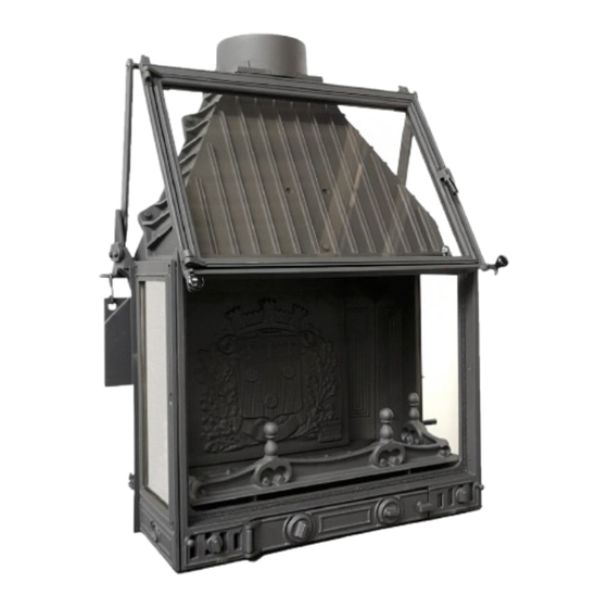
Page 9: Unit Dimensions & Specifications 2.1 Cheminées Philippe Radiante 700 3V
2. UNIT DIMENSIONS & SPECIFICATIONS 2.1 CHEMINÉES PHILIPPE RADIANTE 700 3V PLEASE NOTE: Due to the handmade nature of our fireplaces there maybe a slight variance factor of 1-2mm across all unit dimensions and .5kg in unit weight. - Page 10 UNIT SPECIFICATIONS & DIMENSIONS * Must use supplied flue adaptor Up to 300sqm* HEATING CAPACITY 17.2kW MAXIMUM AVG. HEAT OUTPUT Cast Iron FIREBOX MATERIAL Up to 50cm LOG LENGTH 9”, 11” & 13” FLUE SIZE* 4.5m Metres RECOMMENDED MINIMUM FLUE HEIGHT (From top of spigot) 254kg FIREBOX WEIGHT...
-
Page 11: Freestanding
3. FREESTANDING 3.1 STEP BY STEP INSTALL GUIDE 3.2 BASE & HEARTH DIMENSIONS 3.3 FREESTANDING CLEARANCES 14-15 3.4 SKAMOTEC WALL GUIDELINES 3.5 SKAMTOEC WALL VENTILATION 3.6 FLUE COMPONENTS OVERVIEW 3.7 FLUE SYSTEM CONFIGURATIONS PLEASE NOTE: All diagrams in this manual are for illustration purposes only, DO NOT scale from any of these diagrams. - Page 12 STEP 1: INSPECT THE FIREPLACE & FLUE PENETRATION THEN LAY BASE & HEARTH » Inspect the area to ensure the fireplace and flue, including clearances, base and hearth, will be installed safely and conform to Australian & New Zealand Standards AS/NZS 2918:2018 and the guides in this manual relative to your type of installation »...
- Page 13 HEARTH REQUIREMENTS 300mm* Unless forming an abutment with a wall BASE MINIMUM HEIGHT OF UNIT A 200mm 300mm 350mm .<199mm .400mm MINIMUM HEARTH DEPTH 1000mm* 500mm 425mm 300mm .370mm MINIMUM BASE SIZE: WIDTH: 910mm x DEPTH: 460mm x THICKNESS: Refer to page 8** MINIMUM HEARTH SIZE: WIDTH:1060mm x DEPTH: As per above(B) x THICKNESS: 27mm** The unit must be placed centrally in the 1060mm width hearth.
- Page 14 UNIT GLASS CLEARANCE: A minimum 1500mm from the NON-COMBUSTIBLE CEILING: front glass of the unit to any combustible surfaces must be For freestanding installations where the ceiling height maintained. is less than 2.3 metres from the base of the unit, a CLEARANCES: Mirrors, windows and all other types of non-combustible board must be used on the ceiling...
- Page 15 CORNER CLEARANCES Combustible Wall Combustible Wall Non-Combustible Wall Material All hearth dimensions on this page refer to the unit being raised 200mm or greater above floor level, refer to page 13 IMPORTANT: WALL MATERIAL 850mm COMBUSTIBLE WALL 110mm 50MM SKAMOTEC BOARD + 50MM AIR GAP 150mm 110MM SOLID BRICK (applied directly to combustible wall) 100mm...
- Page 16 SKAMOTEC 225 Also known as “Skamol” board, Skamotec is a lightweight non-combustible board that simplifies the construction process to one building material, therefore eliminating the need for a steel or brick frame construction. It is intended for interior, non-load bearing wall applications and has a maximum service temperature of 1000 degrees celsius RECOMMENDED FIXING OF SKAMOTEC BOARDS &...
- Page 17 SKAMOTEC WALL VENTILATION CONFIGURATIONS (WHEN USING 50MM BATTERNS, SEE PAGE 14) OPTION A: 25MM TOP & BOTTOM AIR GAP The 25mm top and bottom air gap must extend the full width of the Skamotec cavity and can be left open to create a shadow line effect, or alternatively can be faced with a metal grill/vent OPTION B: CONCEALED EXTERNAL VENTS OPTION C: CONCEALED INTERNAL VENTS...
- Page 18 MINIMUM FREESTANDING FLUE KIT COMPONENTS 4.5 METRE 9” DOUBLE SKIN FLUE KIT 4.5 METRE 9” SINGLE SKIN FLUE KIT 9” Flue Adaptor* (Painted) 9” Flue Adaptor* (Painted) 2 x 9” Single Skin Flue 900mm* (Painted) 2 x 9”-11” Double Skin Flue 900mm* (Painted) 9”-11”-13”...
- Page 19 FREESTANDING FLUE CONFIGURATIONS Flat ceiling with Cathedral ceiling Flat ceiling & flat Multi floor with roof space roof flat ceiling and roof space Flat ceiling with Freestanding with External wall 8. Double storey roof space and chimney & offset penetration with single storey offset...
- Page 20 NOTES RADIANTE 700 3V CHEMINÉES PHILIPPE...
-
Page 21: Inbuilt
4. INBUILT 4.1 STEP BY STEP INSTALL GUIDE 4.2 BASE, HEARTH & MANTEL SHELF DIMENSIONS 4.3 INBUILT CAVITY DIMENSIONS 4.4 DEFLECTOR PLATE & GRILLS 4.5 FLUE COMPONENTS OVERVIEW PLEASE NOTE: All diagrams in this manual are for illustration purposes only, DO NOT scale from any of these diagrams. All measurements are in millimetres unless otherwise stated. - Page 22 STEP 1: INSPECT THE FIREPLACE & FLUE PENETRATION THEN LAY BASE & HEARTH » Inspect the area to ensure the fireplace and flue, including clearances, base and hearth, will be installed safely and conform to Australian & New Zealan Standards AS/NZS 2918:2018 and the guides in this manual relative to your type of installation »...
- Page 23 HEARTH REQUIREMENTS HEAT SENSITIVE MATERIALS EXCLUSION ZONES: Minimum 1000mm above and 300mm either side of unit 1000mm BASE MINIMUM HEIGHT OF UNIT A 200mm 300mm 350mm .<199mm .400mm MINIMUM HEARTH DEPTH 1000mm* 500mm 425mm 300mm .370mm *When the unit is raised 199mm or less from floor level, a minimum 1000mm hearth is required in all directions, unless forming an abutment with a wall, refer to page 24.
- Page 24 ENCLOSURE MATERIALS & CLEARANCES: Brick/hebel Enclosure*: Use a minimum 110mm solid brick or hebel with a minimum clearance of 100mm to the back of the unit and 200mm on either side. Skamotec Enclosure**: Use a minimum 50mm Skamotec board with a 50mm air gap behind (using Skamotec battens).
-
Page 25: Deflector Plate & Grills
DEFLECTOR PLATE 9” CENTRE DEFLECTOR PLATE ROCK WOOL BLANKET » Deflector to be galvanised metal sheet (1mm minimum) and installed a minimum 500mm below the ceiling » The rock wool blanket is to be heat resistant with aluminum foil adhered to one face and installed directly on top of the deflector plate with foil side face down. - Page 26 9” Anti Down Draught Cowl 9” Anti Down Draught Cowl *All internal 9” flue must be stainless steel PARTIAL MASONRY INSTALL OVERVIEW FULL MASONRY INSTALL OVERVIEW *ALL ILLUSTRATIONS ON THIS PAGE REFERENCE A SINGLE SIDED MODEL ONLY CHEMINÉES PHILIPPE RADIANTE 7003V...
-
Page 27: Mechanisms & Unit Assembly 5.1 Mechanism Guide
5. MECHANISMS & UNIT ASSEMBLY 5.1 MECHANISM GUIDE 5.2 ASSEMBLY 28-32... - Page 28 LOCATION OF MECHANISMS Swing & lift door with vitro-ceramic glass Door handle Primary air adjustment under grate Damper control (use steel rod supplied to operate) Additional air adjustment Removable ash tray (open door to access) Unlatch handles for lift door operation Counterweight support mechanism PRIMARY AIR &...
- Page 29 STEP 1: GATHER ASSEMBLY In the packaging you will find some parts of this unit not assembled, due to size of the firebox the final assembly must be done prior to the installation of the flue system. 1. Coat around the top part of the base, including the grooves at the back with refactory cement (black can written ROC) 2.
- Page 30 STEP 3: DAMPER ASSEMBLY (INCLUDING FLEXIBLE ROD) THIS ASSEMBLY IS DONE PRIOR TO INSTALLING THE FLUE. IT CAN ALSO BE REMOVED AND RE-ASSEMBLED FOR FLUE SWEEPING FROM INSIDE OF THE FIREBOX. See instructions below: 1. Before removing the damper, remove the baffle (take care to hold the decorative back plate of the unit to avoid it falling), then put the damper into the open (vertical) position.
- Page 31 STEP 4: BACK PLATE, BAFFLE, GRATE, ASH RETAINER & ASH PAN ENSURE THE DAMPER IS FITTED FIRST 1. Place the decorative plate between the lugs on the top and base of the firebox 2. Insert the baffle plate towards the top of the firebox gather and rest it on the back and forward internal cleats 3.
- Page 32 INSTALLING THE MESH SIDES (FOR INBUILT INSTALLATION) To be fixed to either side of the fuel loading door (maybe required when unit is installed inbuilt) RADIANTE 700 3V CHEMINÉES PHILIPPE...
-
Page 33: Operation
6. OPERATION 6.1 BEFORE FIRST IGNITION 6.2 RECOMMENDED FIRE WOOD 6.3 HOW TO LIGHT & BURN SAFELY 36 & 37 6.4 WARNINGS LABELS... - Page 34 BEFORE LIGHTING FOR THE FIRST TIME » For brick enclosures four weeks drying time should be respected to ensure that moisture evaporates accordingly » Once this period has passed, you can light your first fire, with a moderate amount of wood and a reduced opening of the air intake to limit the intensity of the fire, which will allow a progressive rise in temperature within the insert and other elements, to avoid rapid expansion of the materials and thermal shock...
- Page 35 RECOMMENDED FIRE WOODTIME » A well installed wood heater burning Australian hardwoods with a moisture range of 15% to 20% will burn more clean and effectively, giving off abundant heat to circulate around your home » Anything over 20% and your wood heater will not work efficiently. The energy from the fire will be used to reduce moisture in your wood and not produce heat for your house.
- Page 36 MATERIALS REQUIREDTIME » Fire lighters » Kindling » Well seasoned, split hardwood » A lighter or match sticks BEFORE STARTING » Ensure the damper, primary and secondary air inlets are fully open » Before loading, remove any larger pieces of debris from the previous fire. It is recommended to leave a bed of ash inside the fireplace and to never clean it out completely during the colder months »...
- Page 37 USING YOUR CHEMINÉES PHILIPPE SAFELY & EXTENDING LONGEVITY OF THE UNIT & PARTSP » To ensure maximum performance for your fireplace, it is necessary to keep a close eye on it. It is recommended that refueling is carried out several times rather than overloading the unit »...
- Page 38 WARNINGS » Never throw water onto the fire to put it out » The window pane(s) can reach high temperatures by releasing radiated heat; we advise you not to place sensitive objects within 1500mm proximity » Due to extreme temperatures when the unit is lit, ensure adult supervision around young children »...
- Page 39 7. MAINTENANCE 7.1 SERVICING GUIDE 7.2 TROUBLE SHOOTING 7.3 SPARE PARTS...
- Page 40 SERVICE & ONGOING MAINTENANCE » The fireplace should be cleaned twice a year by a professional, including once during the heating period (winter) to ensure the unit and flue are in good order. The various parts of the unit should be checked, including all door ropes and seals, baffle plate, glass, etc, as it may be necessary to replace these »...
- Page 41 OBSERVATION POTENTIAL SOLUTION - Ensure damper and all air inlets are in the open Downdraft; Smoke billowing out of position several minutes before opening the door glass - Check there is sufficient fresh air intake into the room (open a door or window to check) - Ensure the flue is cleared of any creosote build up, engage a professional service if required - Using a moisture meter check the moisture...
- Page 42 PARTS LIST » When requesting spare parts or information, please note the serial number which can be found on the identification plate on the base of the unit on the base of the ash pan chamber » Only use spare parts, in particular the replacement of glass should only be sourced and supplied by Cheminées Philippe Australia »...
- Page 43 8. WARRANTY 8.1 WARRANTY POLICY & EXTENDED WARRANTY 8.2 INSTALLER CHECKLIST FORM...
- Page 44 WARRANTY » The installation guarantee is effective within a framework of compliance with the code of practice, the legislation in force, the installation instructions and the correct use of this fireplace » The warranty period begins when the unit has left the warehouse of Cheminées Philippe Australia »...
- Page 45 (IT IS MANDATORY TO COMPLETE THIS FORM FOR WARRANTY PURPOSES) DATE OF INSTALLATION: Tick Installation of the unit & flue conform to this manual & AS/NZS 2918:2018 All safety clearances and minimum hearth sizes have been abided by All components (including back & baffle plate) have been fitted correctly A test fire has been lit and the unit draws effectively All packaging including any flammable material has been removed The user has been shown the Mechanisms, Operation &...
- Page 46 CHEMINÉES PHILIPPE AUSTRALIA For more information contact your nearest dealer or visit www.chemphilaust.com.au...
Need help?
Do you have a question about the RADIANTE 7003V and is the answer not in the manual?
Questions and answers