
Related Manuals for Sencore MRD 2600


Summary of Contents for Sencore MRD 2600
- Page 1 MRD 2600 Modular Receiver User Manual August 2021 8104S www.sencore.com | 1.605.978.4600 Revision 1.19...
- Page 2 This document may also have links to third-party web pages that are beyond the control of Sencore. The presence of such links does not imply that Sencore endorses or recommends the content on those pages. Sencore acknowledges the use of third-party open source software and licenses in some Sencore products.
- Page 3 MRD 2600 – User Manual Revision History Date Version Description Author 06/10/2013 Initial Release (1.2.0 software) 08/30/2013 Update for ver. 1.2.0 Release 11/21/2013 Update for ver. 1.3.0 Release 3/11/2014 Update for ver. 1.4.0 Release 5/14/2014 Update for ver. 2.0.0 Release 9/18/2014 Update for ver.
- Page 4 If the product has been dropped or damaged in any way. The product exhibits a distinct change in performance. • Replacement Parts: When replacement parts are required, be sure the service technician uses replacement parts specified by Sencore, or parts having the Page 4 (87)
- Page 5 (at the breaker) and send your equipment to be serviced by a qualified technician. • To reduce the risk of shock the MRD 2600 must be connected to a mains socket outlet with a protective earthing connection. •...
- Page 6 MRD 2600 – User Manual FCC Class A Information The MRD 2600 has been tested and found to comply with the limits for a Class A digital device, pursuant to Part 15 of the FCC Rules. These limits are designed to provide reasonable protection against harmful interference when the equipment is operated in a commercial environment.
- Page 7 2. AC Power Cable 3. Quick Start Guide Note: If any option cables were ordered with the MRD 2600 they will be included in the box as well. If any of these items were omitted from the packaging of the MRD 2600 please call 1-800- SENCORE to obtain a replacement.
-
Page 8: Table Of Contents
MRD 2600 Front Panel Overview ................19 Section 4 Operating the Web Interface ............20 MRD 2600 Web Interface Overview ............... 21 Logging into the MRD 2600 Web Interface ............21 Hiding Unused Inputs ..................21 Buttons and Status Indicators ................21 Drag and Drop Menus .................. - Page 9 MRD 2600 – User Manual In-Band Control ....................61 Updating the MRD 2600 ................... 61 Reboot Unit ...................... 63 Reset Defaults....................63 Reporting Panel ....................64 Active Alarms ....................64 Event Logs ....................... 65 Configuring the Logs ..................66 About Panel ......................68 Section 5 Appendices ..................
-
Page 10: Section 1 Overview
MRD 2600 – User Manual Section 1 Overview Introduction This section includes the following topics: Product Introduction ....................11 Front Panel Overview .................... 11 Rear Panel Overview .................... 11 Cooling........................12 Rack Information ....................12 Page 10 (87) -
Page 11: Product Introduction
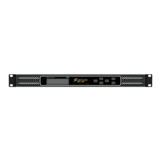
- Mozilla Firefox 3.5 & above Front Panel Overview The MRD 2600 can be controlled from the front panel using the LCD screen and buttons that are shown below. A detailed description of using the front panel can found in Section 3.1. -
Page 12: Cooling
“Error List.” Rack Information The MRD 2600 is intended to be mounted in a standard 19” rack. It occupies 1RU of rack space and the connections are all on the rear of the unit. -
Page 13: Section 2 Installation
MRD 2600 – User Manual Section 2 Installation Introduction This section includes the following topics: Rack Installation ....................14 Power Connection ....................14 AC Power Connection ................... 14 AC Dual Redundant Power Connection (optional) ..........15 DC Power Connection ................... 15 Maintenance ...................... -
Page 14: Rack Installation
MRD 2600, personnel, or property. AC Power Connection The MRD 2600 is intended for use on either 120V or 240V systems. The power supply will automatically detect the system it is connected to. To hook up the power use the following steps: 1. -
Page 15: Ac Dual Redundant Power Connection (Optional)
DC Power Connection The MRD 2600 with the DC chassis option is intended for use on 48V DC systems. A power cable is not included for this option. In order to apply power to the unit in this configuration, simply connect the screw terminals on rear of the unit to the rack’s DC... - Page 16 MRD 2600 – User Manual 3. Use the buttons to Admin ↔↕ >Unit Networking move the cursor to “Unit System Time Networking”, then press the About System button. Voltage Levels Note: The first menu displayed is status menu. In order to begin making changes to networking settings press button.
- Page 17 “Enabled” then press the button to save the selection. Note: It may take up to a minute for the MRD 2600 to obtain an IP address. During this time the unit will display a “busy” message next to DHCP.
-
Page 18: Section 3 Operating The Front Panel
MRD 2600 – User Manual Section 3 Operating the Front Panel Introduction This section includes the following topics: MRD 2600 Front Panel Overview ................19 Page 18 (87) -
Page 19: Mrd 2600 Front Panel Overview
MRD 2600 – User Manual MRD 2600 Front Panel Overview The MRD 2600 front panel allows the user to configure all settings that are present in the web interface using the buttons located on the front of the unit. The screen below is the idle screen of the MRD 2600. -
Page 20: Section 4 Operating The Web Interface
MRD 2600 – User Manual Section 4 Operating the Web Interface Introduction This section includes the following topics: MRD 2600 Web Interface Overview ............... 21 Main Panel ......................23 Admin Panel ......................50 Reporting Panel ....................64 About Panel ......................68... -
Page 21: Mrd 2600 Web Interface Overview
MRD 2600 – User Manual MRD 2600 Web Interface Overview Logging into the MRD 2600 Web Interface To open the MRD 2600 web interface use one of the following supported browsers and navigate to the unit’s IP address: • Internet Explorer 7 & above •... -
Page 22: Drag And Drop Menus
Drag and Drop Menus Certain menus in the MRD 2600 allow the user to drag and drop items to auto populate fields. Conditional Access is an example of a menu that drag and drop can be used. In the example below a service in the transport stream view on the right hand side of the window is selected and dragged over to auto populate the Service and PIDs in the Conditional Access section. -
Page 23: Main Panel
MRD 2600 – User Manual Main Panel The Main panel of the MRD 2600 web interface is used to configure the unit to route an input to an output. When configuring the MRD 2600 the user begins at the top of the menu and works down. -
Page 24: Configuring Active Inputs
This menu allows the user to configure a primary and backup input. In case there is a TS sync loss on the primary input the MRD 2600 is capable of detecting the failed state and switching to a secondary backup input in order to provide a continuous output. Which input is primary and backup, how the inputs switchover and restore and switchover timing is all user configurable. - Page 25 Manual Only: the unit will not switch inputs automatically. The user must manually TS Sync Loss switch inputs. TS Sync Loss: the MRD 2600 will switch from the primary to the backup input if the primary stream loses synchronization for the duration of the Switchover Interval.
-
Page 26: Configuring Asi Input
MRD 2600 – User Manual Configuring ASI Input This menu allows the user to either Enable or Disable the ASI Input on the MRD 2600. Beginning with revision J main boards the ASI ports can be configured as either an input or output. -
Page 27: Configuring Mpeg/Ip Input
MRD 2600 – User Manual Configuring MPEG/IP Input If the MPEG/IP Input card was selected as a factory installed option, the following menus and options will be available for configuration. This menu allows the user to configure the MPEG/IP inputs. Each MPEG/IP card has two ports that can be set to receive and/or transmit. - Page 28 This is the only setting required to receive a unicast stream. Enabled Enabling FEC (Forward Error Correction) tells the MRD 2600 to look at Destination Disabled Port +2 and Destination Port +4 for a SMPTE 2022 FEC Matrix.
- Page 29 Buffer Mode is set to Size (KB). 1 – 4000 ms Buffer Delay This setting determines how long the input receives signal before the MRD 2600 starts decoding. Increasing this value will allow the MRD 2600 to receive streams on networks with high network jitter. Increasing this value also increases the latency of the unit.
-
Page 30: Configuring Dvb-S/S2/S2X Input
MRD 2600 – User Manual Configuring DVB-S/S2/S2X Input If the DVB-S/S2/S2X input card was selected as a factory installed option, the following menus and options will be available for configuration. This menu allows the user to configure the DVB-S/S2/S2X inputs. The input card is equipped with dual demodulators and four ports (labeled A, B, C and D). - Page 31 DVB-S2/S2X satellite multi-stream (Advanced MRD 26916 licensed feature) LNB Power The MRD 2600 has the ability to provide the necessary voltage to power an LNB. Select 13 VDC the correct voltage to supply to the LNB. Page 31 (87)
-
Page 32: Configuring Dvb-S/S2 Input
18 VDC 22 kHZ Tone Enabled Enabling or disabling the 22khz tone allows the MRD 2600 to trigger the LNB to switch Disabled polarities. Configuring DVB-S/S2 Input If the DVB-S/S2 Input card was selected as a factory installed option, the following menus and options will be available for configuration. - Page 33 Scrambling. In order to receive the stream, enter the value of the incoming signals PL Scrambling code. LNB Power The MRD 2600 has the ability to provide the necessary voltage to power an LNB. Select 13 VDC the correct voltage to supply to the LNB.
-
Page 34: Configuring 8Vsb/Qam Input
MRD 2600 – User Manual NOTE: This is a licensed feature. 0-255 This setting is the ISI (Input Stream Identifier) the MRD 2600 uses to filter multistream input. This option is only available if Multistream is licensed and enabled. Setting... -
Page 35: Configuring Turbo Psk Input
MRD 2600 – User Manual Channel Off Air: 2-69 This setting is for the desired channel to be received. FCC, HRC, or IRC Cable: 2-158 Low RF Level -34 - +40 This is the Low RF Level threshold when (dBmV) -
Page 36: Configuring Dvb-T2/C2/Isdb-T Input
MRD 2600 – User Manual QPSK 7/8 8PSK 2/3 8PSK 3/4 (2.05) 8PSK 3/4 (2.10) 8PSK 3/4 (2.20) 8PSK 5/6 8PSK 8/9 LO Offset 5150 The offset in MHz that the local oscillator is operating. 9750 10600 10750 11250 C-Band: 4GHz – 8GHz... - Page 37 MRD 2600 – User Manual Setting Range Description Receive Enabled This setting allows the user to enable or disable this reception port. Disabled Mode DVB-T This setting allows the user to choose between DVB-T/T2/C/C2 or ISDB-T DVB-T2 modulation schemes. DVB-C...
-
Page 38: Configuring Dvb-Ci Descrambling
Low MER Alarm will be triggered in dB. Configuring DVB-CI Descrambling This section will describe how to configure DVB-CI descrambling in the MRD 2600. First, the user will need to configure the CAM slots. Once this is complete the user can configure which services or PIDs to descramble. - Page 39 4.2.9.1 Configuring DVB-CI Slots This menu allows the user configure the DVB-CI slots in the MRD 2600. The MRD 2600 has two DVB-CI slots, a top and bottom, where CAM Modules can be inserted. Both slots are individually configurable using the Bottom Slot and Top Slot tabs. CAM Modules can be reset manually using the button.
- Page 40 When the Multiservice Descrambling License is purchased, this menu allows the user to select the services the MRD 2600 will descramble using the CAM Modules and Smart Cards inserted into the DVB-CI slots. See Section 4.2.9.1 to configure these slots. The drag and drop method can be used to drag services from the right column to the left column.
-
Page 41: Configuring Conditional Access
MRD 2600 – User Manual Configuring Conditional Access This section will describe how to configure descrambling in the MRD 2600. The MRD 2600 allows decoding of BISS 1 and BISS 2 with additional licensing. Note: BISS 1 and BISS 2 descrambling are licensed separately. - Page 42 MRD 2600 – User Manual Mode E Session If Mode E is selected the user enters the Word BISS session word here Mode E Injected If Mode E is selected the user enters the BISS injected ID here. 4.2.10.2 BISS 2 (BISS-CA) Descrambling This menu allows the user to configure BISS descrambling.
-
Page 43: Pid Filter
Mode CA Public Download If Mode CA Buried is selected, the user is able to download the Public Key from the MRD 2600. The file will be generated as a .pub Mode CA Private Upload If Mode CA Injected is selected, the user will need to upload the Private Key. -
Page 44: Configuring Asi Output
TS. Configuring ASI Output This menu allows the user to configure the ASI output of the MRD 2600. When enabled this output acts as an active loop output of the active input. For example, if the DVB-... -
Page 45: Configuring The Mpeg/Ip Outputs
MRD 2600 – User Manual S/S2 input card is the current active input the ASI output port will output a demodulated signal of the satellite input. Setting Range Description Port Enabled Enable or disable the ASI output port. Disabled Source... - Page 46 MRD 2600 – User Manual Setting Range Description Transmit Enabled Enable or disable the MPEG/IP transmit group. Disabled Source Descrambled Unmodified Input will pass the incoming TS to the output without applying any BISS or DVB-CI Unmodified Input decryption. PID Filter 1-5 Descrambled will output the TS with any applied BISS or DVB-CI decryption.
-
Page 47: Configuring The Mpeg/Ip Mpe Outputs
>1030 and an even number Source Port 0 - 65535 This is the port used by the MRD 2600 to transmit the MPEG/IP stream. TS Packets Per The number of TS packets that are contained IP Packet with a single IP packet. - Page 48 MRD 2600 – User Manual Setting Range Description Transmit Enabled Enable or disable transmission of de-encapsulated MPE data. Disabled Physical Port 1 The physical connector on the MPEG/IP card that Connector will be used to transmit the MPE data. Port 2...
-
Page 49: Viewing Psip Information
MRD 2600 – User Manual Viewing PSIP Information To view the PSIP information for the applied TS, select the View PSI Tables button located on the right hand side of the Inputs section. This will open a new window that displays all of the PSIP information for the applied TS. -
Page 50: Admin Panel
MRD 2600. Changing Unit Password The MRD 2600 can be assigned an access password and the current access password can be changed. In order to make changes to passwords, click the button. A window will appear to enter the new password and re-enter the new password to confirm it. -
Page 51: Profiles
MRD 2600 – User Manual Profiles The MRD 2600 has the ability to save all configured settings to multiple profiles. Profiles can be saved locally, renamed and saved to external storage to be used on other MRD 2600s with the same hardware, licensing, and software version. Profiles can be used to quickly and easily change the configuration of an MRD 2600 to suit different inputs and decoding requirements. -
Page 52: General Settings
MRD 2600 – User Manual General Settings The MRD 2600 can be assigned an alias which is displayed in the upper right hand corner of the web interface. The alias can help define which MRD 2600 the operator is currently logged into. The BISS-E Injected ID for BISS Mode E can also be protected from being accidently changed. -
Page 53: Tacacs+ Configuration
MRD 2600 – User Manual If the MRD 2600 contains a 26127 option card the unit can be configured to have an optional 2 control port. TACACS+ Configuration This feature is to be implemented in tandem with a primary and secondary TACACS+ server that the MRD 2600 can reference. - Page 54 Shared Secret Administrator defined The shared key for all devices to be authenticated by the TACACS+ server. NOTE: Exercise extreme caution when performing changes to this menu as network communication can be lost with the MRD 2600. Setting Range Description Mode...
-
Page 55: Mpeg/Ip Network Configuration
This is the Gateway address assigned to the XXX.XXX.XXX.XXX management port. The 2nd management port of the MRD 2600 can be configured from the web interface. To make changes to which port is the 2nd management port click, the configure control ports button under the Unit Network Configuration section. - Page 56 191.255.0.0 192.0.1.0 - 223.255.255.0 Link Speed Auto Setting Link Speed to Auto allows the MRD 2600 to determine the link speed of the network. If this 1000Mbps/Full is not possible or the user wants to define a link 1000Mbps/Half speed, select one of the other values available.
-
Page 57: Licensing
Sencore. Date/Time The MRD 2600 can be set to synchronize with an NTP server or a manual date and time can be defined by the user. Click the button to configure the date and time. -
Page 58: Configuring Snmp
MRD 2600 – User Manual Setting Range Description Update Mode Setting to NTP uses the local network’s NTP server to synchronize date and time. Manual Manual allows the user to define a date and time. NTP Server Four decimal octets: This is the IP Address or Domain Name of the local NTP Server on the network. - Page 59 The MRD 2600 stores the SNMP MIB files for the currently installed version of software on the unit. These files can be downloaded directly from the MRD 2600 by clicking on button. The screen below will appear where the files can be downloaded and saved off of the unit.
-
Page 60: Syslog
MRD 2600 – User Manual Syslog The MRD 2600 can be configured to send error and event logs formatted in the syslog protocol to a remote user specified Syslog server. Action Range Description State Enabled Enable or Disable sending messages to Syslog server. -
Page 61: In-Band Control
The In-Band Control is used to change settings and receive updates from data within a PID in the incoming TS, as injected by the Sencore CMD 4000 In-band Control Server. The following menu allows the user to configure the In-Band Control settings. To configure the In-Band Control settings click the button. - Page 62 MRD 2600 – User Manual button. The current version and uploaded version are displayed in the Software Versions section. The MRD 2600 will reboot after a software update is complete. Note: When updating from software versions older than 3.0.0 to 4.3.0 or newer the password may be changed to mpeg101 Note: When updating from software version 3.0.0 or newer, the existing...
-
Page 63: Reboot Unit
4.3.12.2 Rollback Software Updates The MRD 2600 is capable of reverting back to a previous version of software using the Rollback feature. The MRD 2600 maintains two separate software images; one is the most current version of software with all current settings and the other is the previous version of software with all settings. -
Page 64: Reporting Panel
MRD 2600 – User Manual The MRD 2600 will prompt the user to confirm the reset. The unit will reboot once the reset is confirmed. Reporting Panel tab in the MRD 2600 contains logs for active alarms currently affecting the unit and an event log. -
Page 65: Event Logs
Event Log menu. This list displays all of the events and alarms that have affected the unit. The MRD 2600 stores up to four days’ worth of logs. The logs can be cleared manually by clicking the button. -
Page 66: Configuring The Logs
MRD 2600. The allows the user to configure the events reported by the MRD 2600. Each column and its function are described below. A user configured time offset can also be applied to allow viewing the logs in a local time zone. - Page 67 Relay will not be closed. See Appendix D for pinout. Relay # This column allows the user to select which of the three relays available on the MRD 2600 will be closed when the alarm is raised. Page 67 (87)
-
Page 68: About Panel
MRD 2600 – User Manual Relay Duration This column is only available in the tab. This option allows the user to define the length of time in milliseconds the relay will be closed after the event is logged. This setting can be configured from 100-1000 milliseconds. -
Page 69: Section 5 Appendices
MRD 2600 – User Manual Section 5 Appendices Introduction This section includes the following appendices: – Acronyms and Glossary ............ 70 – Error and Event List ............73 – Specifications ..............75 – Pinouts for Relay Connectors ........... 83 – Open Source Software ............84 –... -
Page 70: Acronyms And Glossary
MRD 2600 – User Manual – Acronyms and Glossary 8VSB: Vestigial sideband modulation with 8 discrete amplitude levels. 16VSB: Vestigial sideband modulation with 16 discrete amplitude levels. AAC: Advanced Audio Coding AC-3: Also known as Dolby Digital AES: Audio Engineering Society... - Page 71 MRD 2600 – User Manual High level: A range of allowed picture parameters defined by the MPEG-2 video coding specification which corresponds to high definition television. I/O: Input/Output IP: Internet Protocol Kbps: 1000 bit per second LED: Light Emitting Diode...
- Page 72 MRD 2600 – User Manual RGBHV: Red, Green, Blue, Horizontal, Vertical RO: Read Only RPM: Revolutions Per Minute RRT: Rating Region Table RS-232: Recommended Standard. A standard for serial binary data interconnection. RU: Rack Unit RW: Read/Write SD: Standard Definition...
-
Page 73: Error And Event List
Service that BISS key is assigned to descramble is not present in the incoming stream. Backup Input Active Primary input is currently in a failed condition and the MRD 2600 Condition has failed over to the Backup input. Bitrate Exceeded Error Total incoming transport stream bitrate has exceeded 213 Mbps. - Page 74 The MRD 2600 has detected that the transport stream error indicator is present on the active input. Transport Stream Not The MRD 2600 has detected that the transport stream from the Present active input is no longer present. TS Sync Loss Transport stream sync for IP stream is not detected.
-
Page 75: Specifications
MRD 2600 – User Manual – Specifications MRD 2600 – Base Unit Includes – Display, keypad, embedded controller, chassis/case, power supply/line cord System – Display Type: Display Configuration: 240 pixels by 64 pixels Keypad: Snap-dome Membrane Front Panel Lockout: Password control, up to 8 alpha-numeric characters... - Page 76 MRD 2600 – User Manual Line Cord: Detachable, 3-prong Dual Redundant AC Power Option– Operating Voltage: 100-240VAC PSU Max Power: 150W Base Unit with no option cards – Current Draw: 38-40W Base Unit with active ASI input – 54-55W MPEG/IP option card with active input –...
- Page 77 MRD 2600 – User Manual ASI Input and Output Features General – Connector: 2x BNC, Female 75Ω Impedance: ≥15dB, 3.5 to 270 MHz Return Loss: ASI Serial TS Input / Output – Number of ASI Inputs: 1 or 2 (rev j or later)
- Page 78 MRD 2600 – User Manual Mode 1 with Session Word Mode E with Session Word and Injected ID BISS 2 Modes: Mode 0 Mode 1 with Session Word Mode E with Session Word and Injected ID Mode CA with Public Key and Injected Private Key...
- Page 79 MRD 2600 – User Manual Number of inputs: 4 (A, B, C and D) Connector: F-81 Type, Female (4) Impedance: 75 Ohms Return Loss: >9 dB Separation: >50 dB adjacent, >60 dB non-adjacent RF frequency: 950 MHz to 2150 MHz in 100 kHz steps...
- Page 80 MRD 2600 – User Manual DVB-S2 Advanced (MRD 26916) Adds – Modulation: 16APSK, 32APSK, 64APSK Modulation/Coding: Supported Rates: 16APSK: 2/3, 3/4, 4/5, 5/6, 8/9, 9/10 32APSK: 3/4, 4/5, 5/6, 8/9, 9/10 64APSK: 32/45-L, 11/15, 7/9, 4/5, 5/6 Symbol Rate: 0.5-60 MSps...
- Page 81 MRD 2600 – User Manual LNB Power Off/13/14/18/19VDC @ >450mA LNB voltage regulation: ± 4% 22 kHz Tone: Off/On @ 650 mV (± 250 mV) peak-peak DVB-S – Standard: EN 300 421 FEC Code: Conv. + Reed-Solomon Modulation: QPSK Modulation/Coding supported:...
- Page 82 MRD 2600 – User Manual 8VSB – Standard: ATSC A/53E Decoding Levels: Nyquist Roll Off (Alpha): 11.5% DVB-T2/C2/ISDB-T Input Module Option General – 42 MHz – 1002 MHz Frequency Range: Number of inputs: Connector: F-Type, Female Impedance: 75 Ohms Sensitivity:...
-
Page 83: Pinouts For Relay Connectors
MRD 2600 – User Manual – Pinouts for Relay Connectors Relay Pinout 9-pin Connector Function Relay 1 Normally Open Relay 1 Normally Closed Relay 2 Common Relay 3 Normally Open Relay 3 Normally Closed Relay 1 Common Relay 2 Normally Open... -
Page 84: Open Source Software
MRD 2600 – User Manual – Open Source Software The MRD 2600 includes: Package Version License Copyright AT32 UC3B Software 1.7.0 2009, Atmel Corporation Framework BusyBox 1.20.1 GPL Version 2, June Erik Anderson, et. al. 1991 DejaVu Fonts 2.35 Free 2003, Bitstream;... - Page 85 MRD 2600 – User Manual OpenSSL 1.0.1c BSD-Like 1998-2008 The OpenSSL Project, 1995-1998 Eric Young OProfile 0.9.7 GPL Version 2, June John Levon, Philippe 1991 Elie, et. al PCRE 8.30 1997-2012 University of Cambridge, 2007-2008 POPT 1.14 1998 Red Hat Software qDecoder 12.0.4...
-
Page 86: Warranty
– Support and Contact Information Returning Products for Service or Calibration The MRD 2600 is a delicate piece of equipment and needs to be serviced and repaired by Sencore. Periodically it is necessary to return a product for repair or calibration. In order to expedite this process please carefully read the instructions below. - Page 87 Sencore Inc. 3200 Sencore Drive Sioux Falls, SD 57107 USA www.sencore.com Copyright © 2021 Sencore Inc. 1.605.978.4600...
Need help?
Do you have a question about the MRD 2600 and is the answer not in the manual?
Questions and answers