
Related Manuals for Sencore MRD 5800


Summary of Contents for Sencore MRD 5800
-
Page 1: User Manual
MRD 5800 Advanced Modular Receiver User Manual September 2016 8089Q www.sencore.com | 1.605.978.4600 Revision 1.18... - Page 2 Inquiries should be made directly to those companies. This document may also have links to third-party web pages that are beyond the control of Sencore. The presence of such links does not imply that Sencore endorses or recommends the content on those pages. Sencore acknowledges the use of third-party open source software and licenses in some Sencore products.
-
Page 3: Revision History
MRD 5800 – User Manual Revision History Date Version Description Author 10/31/2012 First Draft 02/04/2013 Initial Release 04/18/2013 Specification Edits and GUI Changes 06/19/2013 Specifications Edits 06/20/2013 Edit & Updates for ver. 1.1.2 Release 07/10/2013 Edits 08/30/2013 Update for ver. 1.2.0 Release 11/21/2013 Update for ver. -
Page 4: Safety Instructions
• Replacement Parts: When replacement parts are required, be sure the service technician uses replacement parts specified by Sencore, or parts having the same operating characteristics as the original parts. Unauthorized part substitutions made may result in fire, electric shock or other hazards. -
Page 5: Safety Precautions
(at the breaker) and send your equipment to be serviced by a qualified technician. • To reduce the risk of shock the MRD 5800 must be connected to a mains socket outlet with a protective earthing connection. •... - Page 6 MRD 5800 – User Manual FCC Class A Information The MRD 5800 has been tested and found to comply with the limits for a Class A digital device, pursuant to Part 15 of the FCC Rules. These limits are designed to provide reasonable protection against harmful interference when the equipment is operated in a commercial environment.
-
Page 7: Package Contents
3. Quick Start Guide 4. AC Power Cable Note: If any option cables were ordered with the MRD 5800, they will be included in the box as well. If any of these items were omitted from the packaging of the MRD 5800 please call 1- 800-SENCORE to obtain a replacement. -
Page 8: Table Of Contents
MRD 5800 Front Panel Overview ................19 Section 4 Operating the Web Interface ............20 MRD 5800 Web Interface Overview ................21 4.1.1 Logging into the MRD 5800 Web Interface ............21 4.1.2 Hiding Unused Inputs ................... 21 4.1.3 Buttons and Status Indicators................21 4.1.4... - Page 9 – Pinouts for Analog Audio and Relay Connectors ..108 Appendix E – MRD 5800 Audio Explanation ......... 109 Appendix F – MRD 5800 Discrete Audio Configuration ....... 112 Appendix G – Open Source Software ............. 113 Appendix H – Warranty ................115 Appendix I –...
-
Page 10: Section 1 Overview
MRD 5800 – User Manual Section 1 Overview Introduction This section includes the following topics: Product Introduction ....................11 Front Panel Overview ....................11 Rear Panel Overview ....................11 Cooling ........................12 Rack Information ......................12 Page 10 (116) -
Page 11: Product Introduction
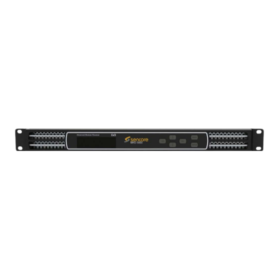
Front Panel Overview The MRD 5800 can be controlled from the front panel using the LCD screen and buttons that are shown below. A detailed description of using the front panel can found in Section 3.1. All hardware listed below comes standard except for the DVB-CI slots which are a factory installed option. -
Page 12: Cooling
“Error List.” Rack Information The MRD 5800 is intended to be mounted in a standard 19” rack. It occupies 1RU of rack space and the connections are all on the rear of the unit. -
Page 13: Section 2 Installation
MRD 5800 – User Manual Section 2 Installation Introduction This section includes the following topics: Rack Installation ......................14 Power Connection ..................... 14 AC Power Connection ....................14 AC Dual Redundant Power Connection (optional) ............ 15 DC Power Connection ....................15 Maintenance ...................... -
Page 14: Rack Installation
1.3 for grounding location. Power Connection Using the proper power connections is vital to the safe operation of the MRD 5800. Only use the supplied 3-prong power connector or one with equal specifications. NEVER tamper with or remove the 3 –... -
Page 15: Ac Dual Redundant Power Connection (Optional)
DC Power Connection The MRD 5800 with the DC chassis option is intended for use on 48V DC systems. A power cable is not included for this option. In order to apply power to the unit in this configuration, simply connect the screw terminals on rear of the unit to the rack’s DC... - Page 16 MRD 5800 – User Manual 3. Use the buttons to Admin ↔↕↵ >Unit Networking move the cursor to “Unit Networking”, System Time then press the button. About System Voltage Levels Note: The first menu displayed is status menu. In order to begin making changes to networking settings press button.
- Page 17 “Enabled” then press the button to save the selection. Note: It may take up to a minute for the MRD 5800 to obtain an IP address. During this time the unit will display a “busy” message next to DHCP.
-
Page 18: Section 3 Operating The Front Panel
MRD 5800 – User Manual Section 3 Operating the Front Panel Introduction This section includes the following topics: MRD 5800 Front Panel Overview ................19 Page 18 (116) -
Page 19: Mrd 5800 Front Panel Overview
MRD 5800 – User Manual MRD 5800 Front Panel Overview The MRD 5800 front panel allows the user to configure all settings that are present in the web interface using the buttons located on the front of the unit. The screen below is the idle screen of the MRD 5800. -
Page 20: Section 4 Operating The Web Interface
MRD 5800 – User Manual Section 4 Operating the Web Interface Introduction This section includes the following topics: MRD 5800 Web Interface Overview ................21 Main Panel ......................... 22 Admin Panel ......................72 Reporting Panel ......................87 About Panel ....................... 91... -
Page 21: Mrd 5800 Web Interface Overview
MRD 5800 Web Interface Overview 4.1.1 Logging into the MRD 5800 Web Interface To open the MRD 5800 web interface use one of the following supported browsers and navigate to the unit’s IP address: • Internet Explorer 7 & above •... -
Page 22: Drag And Drop Menus
4.1.4 Drag and Drop Menus Certain menus in the MRD 5800 allow the user to drag and drop items to auto populate fields. Conditional Access and Service Selection menus are some examples of menus that drag and drop can be used. In the example below a service in the transport stream view on the right hand side of the window is selected and dragged over to auto populate the PIDs in the service selection section. -
Page 23: Configuring Active Inputs
This menu allows the user to configure a primary and backup input. In case there is an input failover the MRD 5800 is capable of detecting the failed state and switching to a secondary backup input in order to provide a continuous output. Which input is primary and backup, how the inputs switchover and restore and switchover timing is all user configurable. - Page 24 MRD 5800 – User Manual Active Input Indicator Active Input and Failover Configuration Menu Setting Range Description Primary Input Used for both normal operation and input failover settings. During normal operation this MPEG/IP Slot X Stream X input will be the active input.
-
Page 25: Configuring Asi Input
4.2.2 Configuring ASI Input This menu allows the user to either Enable or Disable the ASI Input on the MRD 5800. Beginning with revision J main boards the ASI ports can be configured as either an input or output. Earlier revision remain configured as 1 input and 1 ouput port. Main board version can be located on the About tab under the Options section. -
Page 26: Configuring Mpeg/Ip Input
Options section. Port Enabled This setting allows the user to enable or disable the ASI Input to the MRD 5800. Disabled Null Stripped Disabled Enabling Null Stripped allows the MRD 5800 to receive streams that do not contain null Enabled packets. - Page 27 0 - 65535 This is the UDP port the source device is sending to. This is the only setting required to receive a unicast stream. Enabled Enabling FEC (Forward Error Correction) tells the MRD 5800 to look at Destination Page 27 (116)
- Page 28 Disabled packets. (i.e. VBR TS Streams) RTP SSRC Enabled Enabling RTP SSRC allows the MRD 5800 to filter the input by the user defined value. Only Disabled streams containing the user defined value will be received by the MRD 5800.
-
Page 29: Configuring Dvb-S/S2 Input
MRD 5800 – User Manual IP statistics menu 4.2.4 Configuring DVB-S/S2 Input If the DVB-S/S2 Input card was selected as a factory installed option, the following menus and options will be available for configuration. This menu allows the user to configure the DVB-S/S2 inputs. - Page 30 Scrambling. In order to receive the stream, enter the value of the incoming signals PL Scrambling code. LNB Power The MRD 5800 has the ability to provide the necessary voltage to power an LNB. Select 13 VDC the correct voltage to supply to the LNB.
-
Page 31: Configuring 8Vsb/Qam Input
DVB-S2 Mode. NOTE: This is a licensed feature. 0-255 This setting is the ISI (Input Stream Identifier) the MRD 5800 uses to filter multistream input. This option is only available if Multistream is licensed and enabled. 4.2.5... -
Page 32: Configuring Turbo Psk Input
MRD 5800 – User Manual FCC, HRC, or IRC Cable: received. 2-158 Low RF Level -34 - +40 This is the Low RF Level threshold when the (dBmV) Low Level Alarm will be triggered in dBmV Low MER (dB) This is the Low MER threshold when the Low 0 - 40 MER Alarm will be triggered in dB. -
Page 33: Configuring Dvb-T2/C2/Isdb-T Input
MRD 5800 – User Manual 8PSK 5/6 8PSK 8/9 LO Offset 5150 The offset in MHz that the local oscillator is operating. 9750 10600 10750 11250 Satellite C-Band: 4GHz – 8GHz If LO Offset is set to 0 then L-Band frequency... - Page 34 MRD 5800 – User Manual Setting Range Description Recieve Enabled This setting allows the user to enable or disable this reception port. Disabled Mode DVB-T This setting allows the user to choose between DVB-T/T2/C/C2 or ISDB-T DVB-T2 modulation schemes. DVB-C...
-
Page 35: Configuring Dvb-Ci Descrambling
4.2.8.1 Configuring DVB-CI Slots This menu allows the user configure the DVB-CI slots in the MRD 5800. The MRD 5800 has two DVB-CI slots, a top and bottom, where CAM Modules can be inserted. Both slots are individually configurable using the Bottom Slot and Top Slot tabs. CAM Modules can be reset manually using the button. - Page 36 4.2.8.2 Configuring Service Descrambling This menu allows the user to select the services the MRD 5800 will descramble using the CAM Modules and Smart Cards inserted into the DVB-CI slots. See Section 4.2.8.1 to configure these slots. These options are applicable only if the Mode in the DVB-CI settings is set to Selected PIDs or Selected Services (Refer to Section 4.2.8.1).
-
Page 37: Configuring Biss Descrambling
DVB-CI Service Descrambling Menu 4.2.9 Configuring BISS Descrambling This section will describe how to configure BISS descrambling in the MRD 5800. There are two types of BISS descrambling. In “Descramble All PIDs” or “Descramble Decoded PIDs” mode, the user simply configures a BISS key set and selects it from the drop down. - Page 38 MRD 5800 – User Manual BISS Menu Setting Range Description Operation Mode Disabled Descramble Decoded PID’s will descramble the pids that are currently assigned to be Descramble Decoded decoded by the MRD 5800. PIDs Descramble Selected Services will allow the...
-
Page 39: Configuring Service Selection
BISS Service Descrambling Menu 4.2.10 Configuring Service Selection This menu allows the user to configure the PIDs or Service the MRD 5800 will decode. Depending on the Selection Mode that is set, the menu will change to reflect the applicable settings. - Page 40 PAT if a transport stream is present. On Backup Use Primary Service Sets the service the MRD 5800 will tune to in case of an input failover. If Use Primary Use Backup Service Service is selected the MRD 5800 will tune to the service name specified in the Primary section.
- Page 41 Range Description On Backup Use Primary PIDs Sets the PIDs the MRD 5800 will tune to in case of an input failover. If Use Primary PIDs Use Backup PIDs is selected the MRD 5800 will tune to the PIDs specified in the Primary PID column. If...
- Page 42 MRD 5800 – User Manual Auto Seek Menu Page 42 (116)
-
Page 43: Configuring Video Services
The menu allows the user to configure the SDI, Digital Video and Composite output formats of the MRD 5800. Please note that the composite video output is only active if the output video format is SD. Overlays and image insertion are configured in this menu as well. - Page 44 Ratio Auto Conversion MRD 5800 uses the 4x3 Conversion Mode setting to format video. If 4x3 Auto Conversion is set to AFD the MRD 5800 will apply the conversion defined by the AFD code in the incoming stream. If 4x3 Auto...
-
Page 45: Configuring Secondary Video Services
This menu, if applicable, allows the user to configure the simultaneous SDI, and the second Composite output of the MRD 5800. Please note the simultaneous SDI output is limited to SD only. Also note the simultaneous SDI and simultaneous Composite outputs will output the same selected service as the primary video output. - Page 46 5800 will output. 720x480i (4x3 or 16x9) @ 29.97Hz Raster Mode Solid Color If no input is present the MRD 5800 will output either the last frame present or raster. Last Frame Raster Color Black, White, Yellow, If no input is present and solid color option is Cyan, Magenta, Red, chosen the MRD 5800 will output raster.
-
Page 47: Configuring Audio
MRD 5800 – User Manual 4.2.13 Configuring Audio This menu allows the user to configure the audio downmix settings or select a pair of discrete audio channels(if the 5.1 discrete audio license is present). Two audio presets are available: Transmission and Monitor. These presets can be applied by clicking the button. -
Page 48: Configuring Genlock
If the Genlock Reference option was selected as a factory installed option, the following menus and options will be available for configuration. This menu allows the user to configure the genlock reference used by the MRD 5800. The MRD 5800 can be configured to use an external user provided reference or disabled completely. -
Page 49: Scte35
If the SCTE35 license is enabled, the following menus and options will be available for configuration. The SCTE35 to SCTE104 and SCTE35 to Relay options are used in an application where the MRD 5800 is receiving a transport stream with SCTE35 DPI splice messages. - Page 50 MRD 5800 – User Manual the MRD 5800 will report an error Page 50 (116)
- Page 51 MRD 5800 – User Manual Setting Range Description Relay Triggering Enabled Enable or Disable selected Trigger Disabled Relay Output Relay 1 Select which Relay the configured trigger will use. See appendix D for relay pinout. Relay 2 Relay 3 Event ID Filter...
- Page 52 MRD 5800 – User Manual Latch Timeout (ms) 1-300 Specify a duration for latch mode. Note: Receiving a Return to Network message will override the latch timeout. Setting Range Description State Enabled Enable or Disable SCTE 35 message Insertion Disabled...
-
Page 53: Esam
MRD 5800 – User Manual Avail Num 0-255 Authentication for a specific avail in the Unique Program ID Avails Expected 0-255 Number of Avails expected in the current viewing event Messages can be manually inserted by clicking the green arrow that is shown when the SCTE 35 section is expanded as shown below. - Page 54 Enable or Disable insertion Disabled Port 0-65535 Port on which the MRD 5800 will listen for SCTE 35 messages from the ESAM server SCTE 35 Pid present PID on which the SCTE 35 messages will be in TS inserted in the transport stream...
-
Page 55: Configuring Ancillary Data Options
MRD 5800 – User Manual 4.2.17 Configuring Ancillary Data Options This menu allows the user to configure processing options relating to ancillary (ANC/VBI) data generation. Currently it contains options for Source ID and, if the SCTE35 license is enabled, it will also allow the user to configure the filter mode for SCTE104 messages. - Page 56 MRD 5800 – User Manual SD SDI Output Configuration Menu General Setting Range Description Video Loss Mode Disable SDI Setting to Disable SDI disables the SDI output of the MRD in case of an error state. Display Raster Setting to Display Raster the MRD will...
- Page 57 4-19 to embed data. SD SDI VBI Embedding When the MRD 5800 is configured to output SD video the VBI data can be encoded into the vertical blanking as a VBI waveform. The options below allow the user to enable or disable these waveforms.
- Page 58 MRD 5800 – User Manual Disabled embedded is dependent on data in the incoming stream. Enabled Enable/Disable Widescreen Signaling (WSS) embedding in the VBI. WSS is output on line Disabled 23 in the VBI. Enabled Enable/Disable Video Program System (VPS) embedding in the VBI. VPS is output Disabled on line 16 in the VBI.
- Page 59 MRD 5800 – User Manual HD SDI Output Configuration Menu General Setting Range Description Video Loss Mode Disable SDI Setting to Disable SDI squelches the SDI output of the MRD in case of an error state. Display Raster Setting to Display Raster the MRD will...
-
Page 60: Configuring Sdi Audio Embedding
With additional licensing the MRD 5800 can handle up to eight unique audio services. When licensed for eight audio services the user will have eight audio pairs available to embed audio in the... - Page 61 MRD 5800 – User Manual SDI. These four groups consist of eight pairs, with two pairs to each group. All audio pairs share the same options. SDI Embedded Audio Configuration Menu Setting Range Description Group 1-4 Assigning a PCM audio to a Group Pair will embed...
-
Page 62: Configuring Secondary Sdi Outputs
MRD 5800 – User Manual 4.2.20 Configuring Secondary SDI Outputs The following menus allow the user to configure the embedded audio and auxiliary data in the secondary, simultaneous SDI video output. All VANC embedding Line settings contain the values 4 through 19. - Page 63 MRD 5800 – User Manual General Setting Range Description Video Loss Mode Setting to Disable SDI disables the SDI Disable SDI output of the MRD in case of an error state. Display Raster Setting to Display Raster the MRD will...
-
Page 64: Configuring Secondary Sdi Audio Embedding
MRD 5800 – User Manual SD SDI VBI Embedding When the MRD 5800 is configured to output SD video the VBI data can be encoded into the vertical blanking as a VBI waveform. The options below allow the user to enable or disable these waveforms. - Page 65 MRD 5800 – User Manual Secondary SDI Embedded Audio Configuration Menu Setting Range Description Group 1-4 Assigning a PCM audio to a Group Pair will embed the decoded or downmixed two channel audio using Pair 1-2 Audio 1-8 PCM Section the settings defined in 4.2.10.
-
Page 66: Configuring Composite Output
This menu allows the user to configure the composite video output (primary and secondary if applicable) of the MRD 5800. Color subcarriers and VBI embedding are configured in this menu. Please note that the composite video output is only active if the output video format is SD. -
Page 67: Configuring Analog Audio Output
4.2.23 Configuring Analog Audio Output This menu allows the user to configure the analog output outputs of the MRD 5800. Four analog audio outputs are available. The dBu level of the outputs can be adjusted for each of the four audio outputs. For the Analog Output connector pin out refer to Appendix C. -
Page 68: Configuring Digital Audio Output
4.2.24 Configuring Digital Audio Output This menu allows the user to configure the digital audio outputs of the MRD 5800. The number of outputs available directly correlates with the number of audio services the unit is licensed to support. Up to eight digital audio outputs are available. -
Page 69: Configuring Asi Output
4.2.26 Configuring ASI Output This menu allows the user to configure the ASI output of the MRD 5800. When enabled this output acts as an active loop output of the active input. For example, if the DVB- S/S2 input card is the current active input the ASI output port will output a demodulated signal of the satellite input. -
Page 70: Configuring The Mpeg/Ip Outputs
MRD 5800 – User Manual Setting Range Description Port Enabled Enable or disable the ASI output port. Disabled Source Unmodified Input Unmodified Input will pass the incoming TS to the output without applying any BISS or DVB-CI Descrambled decryption Descrambled and... - Page 71 MRD 5800 – User Manual Setting Range Description Transmit Enabled Enable or disable the MPEG/IP transmit group. Disabled Source Unmodified Input Unmodified Input will pass the incoming TS to the output without applying any BISS or DVB-CI Descrambled decryption. Descrambled and...
-
Page 72: Configuring The Mpeg/Ip Mpe Outputs
>1030 and an even number Source Port 0 - 65535 This is the port used by the MRD 5800 to transmit the MPEG/IP stream. TS Packets Per IP The number of TS packets that are contained with Packet a single IP packet. - Page 73 MRD 5800 – User Manual Setting Range Description Transmit Enabled Enable or disable transmission of de-encapsulated MPE data. Disabled Physical Port 1 The physical connector on the MPEG/IP card that Connector will be used to transmit the MPE data. Port 2...
-
Page 74: Viewing Psip Information
MRD 5800 – User Manual 4.2.29 Viewing PSIP Information To view the PSIP information for the applied TS, select the View PSI Tables button located on the right hand side of the Inputs section. This will open a new window that displays all of the PSIP information for the applied TS. -
Page 75: Admin Panel
MRD 5800 – User Manual Admin Panel To access the Admin Control Panel, click on the tab. This menu allows the user to control many aspects of the MRD 5800. Page 75 (116) -
Page 76: Changing Unit Password
4.3.2 Profiles The MRD 5800 has the ability to save all configured settings to multiple profiles. Profiles can be saved locally, renamed and saved to external storage to be used on other MRD 5800s. Profiles can be used to quickly and easily change the configuration of an MRD 5800 to suit different inputs and decoding requirements. -
Page 77: General Settings
The management port of the MRD 5800 can be configured from the web interface. To make changes to the management port click, the button under the Unit Network Configuration section. If the MRD 5800 contains a 58127 option card the unit can be configured to have an optional 2 control port. Page 77 (116) -
Page 78: Mpeg/Ip Network Configuration
This is the Gateway address assigned to the XXX.XXX.XXX.XXX management port. The 2nd management port of the MRD 5800 can be configured from the web interface. To make changes to which port is the 2nd management port click, the configure control ports button under the Unit Network Configuration section. - Page 79 MRD 5800 – User Manual MRD 5800 can be configured from the web interface. To configure the Default Gateway and ICMP Response settings click the button. Setting Range Description Default Gateway Port 1 Setting to Port 1 uses the gateway address of port 1 as the default gateway.
-
Page 80: Licensing
4.3.7 Date/Time The MRD 5800 can be set to synchronize with an NTP server or a manual data and time can be defined by the user. Click the button to configure the date and time. These values are used to timestamp entries in the Alarm and Event logs under the Reporting tab. -
Page 81: Configuring Snmp
MRD 5800 – User Manual Setting Range Description Update Mode Setting to NTP uses the local network’s NTP server to synchronize date and time. Manual allows the Manual user to define a date and time. NTP Server Four decimal octets: This is the IP Address or Domain Name of the local NTP Server on the network. - Page 82 IP address. 4.3.8.3 Download SNMP MIB Files The MRD 5800 stores the SNMP MIB files for the currently installed version of software on the unit. These files can be downloaded directly from the MRD 5800 by clicking on Page 82 (116)
-
Page 83: Syslog
The screen below will appear where the files can be downloaded and saved off of the unit. 4.3.9 Syslog The MRD 5800 can be configured to send error and event logs formatted in the syslog protocol to a remote user specified Syslog server. Action Range... -
Page 84: In-Band Control
The In-Band Control is used to change settings and receive updates from data within a PID in the incoming TS, as injected by the Sencore CMD 4000 In-band Control Server. The following menu allows the user to configure the In-Band Control settings. To configure the In-Band Control settings click the button. - Page 85 4.3.11.2 Rollback Software Updates The MRD 5800 is capable of reverting back to a previous version of software using the Rollback feature. The MRD 5800 maintains two separate software images; one is the most current version of software with all current settings and the other is the previous version of software with all settings.
-
Page 86: Reboot Unit
4.3.12 Reboot Unit The MRD 5800 can be rebooted from the web interface. In order to perform a reboot click the button. The MRD 5800 will prompt the user to confirm the reboot. -
Page 87: Reporting Panel
MRD 5800 – User Manual Reporting Panel tab in the MRD 5800 contains logs for active alarms currently affecting the unit and an event log. The active alarms are updated periodically in order to reflect the real-time state of the unit. Once an error is cleared it will be cleared from the active alarms window. -
Page 88: Event Logs
Event Log menu. This list displays all of the events and alarms that have affected the unit. The MRD 5800 stores up to four days’ worth of logs. If the unit is rebooted or powered off and on the event logs are cleared. -
Page 89: Configuring The Logs
4.4.3 Configuring the Logs The MRD 5800 allows the user to configure alarms and events. Events and alarms can be hidden, set to send SNMP traps or close a relay when active. In order to configure these options click the... - Page 90 Relay will not be closed. See Appendix C for pinout. Relay # This column allows the user to select which of the three relays available on the MRD 5800 will be closed when the alarm is raised. Relay Duration This column is only available in the tab.
-
Page 91: About Panel
MRD 5800 – User Manual About Panel Under the tab, there are no user definable parameters but there is information about software versions currently installed, which licenses are installed, how to contact Sencore, and third party software information. Page 91 (116) -
Page 92: Section 5 Appendices
– Specifications ..............99 Appendix D – Pinouts for Analog Audio and Relay Connectors ..108 Appendix E – MRD 5800 Dolby Audio Explanation ....... 109 Appendix F – MRD 5800 Discrete Audio Configuration ....... 112 Appendix G – Open Source Software ............. 113 Appendix H –... -
Page 93: Appendix A - Acronyms And Glossary
MRD 5800 – User Manual Appendix A – Acronyms and Glossary 8VSB: Vestigial sideband modulation with 8 discrete amplitude levels. 16VSB: Vestigial sideband modulation with 16 discrete amplitude levels. AAC: Advanced Audio Coding AC-3: Also known as Dolby Digital AES: Audio Engineering Society... - Page 94 MRD 5800 – User Manual I/O: Input/Output IP: Internet Protocol Kbps: 1000 bit per second LED: Light Emitting Diode LNB: Low-Noise Block MAC: Medium Access Control Main level: A range of allowed picture parameters defined by the MPEG-2 video coding specification with maximum resolution equivalent to ITU-R Recommendation 601.
- Page 95 MRD 5800 – User Manual RU: Rack Unit RW: Read/Write SD: Standard Definition SDI: Serial Digital Interface SFP: Small Form-Factor Pluggable SI: System Information SMPTE: Society of Motion Pictures and Television Engineers SNMP: Simple Network Management Protocol SPTS: Single Program Transport Stream...
-
Page 96: Appendix B - Error And Event List
Audio Not Decoding Audio is corrupted in incoming stream or format is not supported. Auto Video Format Error MRD 5800 is unable to determine the native incoming video in order to format output. BISS Conflicting PIDs PIDs selected to be descrambled by one BISS key are already assigned to be descrambled by another BISS key. - Page 97 Service that BISS key is assigned to descramble is not present in the incoming stream. Backup Input Active Primary input is currently in a failed condition and the MRD 5800 Condition has failed over to the Backup input. Bitrate Exceeded Error Total incoming transport stream bitrate has exceeded 213 Mbps.
- Page 98 The MRD 5800 has detected that the transport stream error indicator is present on the active input. Transport Stream Not The MRD 5800 has detected that the transport stream from the Present active input is no longer present. TS Sync Loss Transport stream sync for IP stream is not detected.
-
Page 99: Appendix C - Specifications
MRD 5800 – User Manual Appendix C – Specifications MRD 5800 – Base Unit Includes – Display, keypad, embedded controller, chassis/case, power supply/line cord System – Display Type: Display Configuration: 240 pixels by 64 pixels Keypad: Snap-dome Membrane Front Panel Lockout:... - Page 100 MRD 5800 – User Manual PSU Max Power: 150W Current Draw: Base Unit with no option cards – 38-40W Base Unit with active ASI input – 54-55W MPEG/IP option card with active input – 2-3W (additional) DVB-S/S2 option card with active input and LNB load of 19V @ 500mA –...
- Page 101 MRD 5800 – User Manual Drive Level: 1.0 Vpp ±10% Genlock Capability – HD – Adjustment of pixels and lines. Max number of dependent on video mode. SD – Adjustment of subcarrier, pixels and lines. Supported Genlock References: NTSC Black Burst PAL-B/G/I/D/M/N Black Burst 1080i x 1920 @ 25, 29.97 and 30fps...
- Page 102 MRD 5800 – User Manual 576i x 544 (4x3 or 16x9) @ 25hz 480i x 720 (4x3 or 16x9) @ 29.97Hz 1080p60 License Adds – 1080p x 1920 (16x9) @ 50, 59.94 and 60Hz SDI (Serial Digital Interface) Video Out –...
- Page 103 MRD 5800 – User Manual Audio Decoding Features Number of Audio Services: Base Unit – 4 Audio Services 8 Audio Service Decode License (MRD 58880) Adds – 4 Audio Services (8 total) Audio Codecs Supported: Dolby Digital (AC-3) & Plus (EAC-3) AAC-LC, HE-AAC, &...
- Page 104 MRD 5800 – User Manual VII (SMPTE RP-186) SDI HANC Data Types: Time Code (SMPTE 12M-2) VBI Waveforms (SDI/Composite): Line 21 Captions (CEA-608) TVG2X, AMOL-48/96 (SCTE-127) Teletext (EN300706) WSS (EN300294) VPS (EN300231)) Timecode in VBI (SMPTE 12M-1) Synchronization with video :...
- Page 105 MRD 5800 – User Manual BISS Descrambling Option Compatibility Standard: DVB-CSA Supported Modes: Base Unit – None BISS Descrambling License (MRD58921) Adds – Mode 1, Mode E, Injected ID No limitation to number of services descrambled per key Multi-BISS descrambling using up to 12 keys...
- Page 106 MRD 5800 – User Manual Tuning: Difference between Satellite frequency and LO frequency Satellite frequency: 950 – 14500 MHz LO frequency: 0 – 12000 MHz, with presets of 0, 5150, 9750, 10600, 10750 and 11250 MHz Packet size: 188 bytes...
- Page 107 MRD 5800 – User Manual Pilot: On/Off Auto Detect DVB-S2 Advanced (MRD 58916) Adds – Modulation: 16APSK, 32APSK Modulation/Coding: Supported Rates: 16APSK: 2/3, 3/4, 4/5, 5/6, 8/9, 9/10 32APSK: 3/4, 4/5, 5/6, 8/9, 9/10 Symbol Rate: 0.5-60 MSym/s Multistream reception:...
-
Page 108: Appendix D - Pinouts For Analog Audio And Relay Connectors
MRD 5800 – User Manual Appendix D – Pinouts for Analog Audio and Relay Connectors AUD 3-4 AUD 1-2 RELAY (DB-15) ANALOG AUDIO 1-2 (DB-15) ANALOG AUDIO 3-4 CHANNEL FUNCTION CHANNEL FUNCTION Channel 1 Left Channel 3 Left Channel 1... -
Page 109: Appendix E - Mrd 5800 Audio Explanation
Appendix E – MRD 5800 Audio Explanation Downmix Audio Setup There are two primary modes of audio down mix operation for the MRD 5800 receiver/decoders. These settings only affect the signal if the digital output is set to PCM. It will also affect those embedded audio channels that are set to a PCM down mix. - Page 110 MRD 5800 – User Manual Audio Output Settings The digital audio services may be set to PCM (AES) or Pass-through (AES data) as an output. This applies to all available sources. The PCM setting will decode and automatically down mix an AC-3 or Dolby Digital Plus stream to two channels of AES audio.
- Page 111 MRD 5800 – User Manual Mono Dual left OUT L = OUT R = IN Mono Dual right OUT L = OUT R = IN Lo/Ro OUT L = L + C + Ls OUT R = R + C + Rs...
-
Page 112: Appendix F - Mrd 5800 Discrete Audio Configuration
MRD 5800 – User Manual Appendix F – MRD 5800 Discrete Audio Configuration Audio Setup Selecting the discrete option differs from downmix in that it simply decodes the selected audio channels rather than downmixing multiple channels into 2 channels. The service selection mode from 4.2.8 must be set to PID lock in order to output 3 pairs of audio... -
Page 113: Appendix G - Open Source Software
MRD 5800 – User Manual For audio services that indicate the specific channels (Lf, Rf, C, Ls, Rs, LFE) the user can select the audio channels to assign to a output using the named discrete options. If the specific channels are not identified (LPCM Audio for example) than the user can use the multi-channel audio service to select the channel pair of the audio service to output. - Page 114 MRD 5800 – User Manual Monit 5.1.1 GPL Version 3, 29 June 07 2010 Tildeslash Ltd. Net-SNMP 5.7.1 1989, 1991, 1992 by Carnegie Mellon Univsty. 4.2.4p7 NTP License 1992-2009 David L. Mills OpenSSL 1.0.1c BSD-Like 1998-2008 The OpenSSL Project, 1995-1998 OProfile 0.9.7...
-
Page 115: Appendix H - Warranty
Appendix I – Support and Contact Information Returning Products for Service or Calibration The MRD 5800 is a delicate piece of equipment and needs to be serviced and repaired by Sencore. Periodically it is necessary to return a product for repair or calibration. In order to expedite this process please carefully read the instructions below. - Page 116 Sencore Inc. 3200 Sencore Drive Sioux Falls, SD 57107 USA www.sencore.com Copyright © 2016 Sencore Inc. 1.605.978.4600...
Need help?
Do you have a question about the MRD 5800 and is the answer not in the manual?
Questions and answers