
Related Manuals for Sencore AG 2600


Summary of Contents for Sencore AG 2600
-
Page 1: User Manual
AG 2600 Receiver Card User Manual April 2017 8129I www.sencore.com | 1.605.978.4600 Revision 1.8... - Page 2 This document may also have links to third-party web pages that are beyond the control of Sencore. The presence of such links does not imply that Sencore endorses or recommends the content on those pages. Sencore acknowledges the use of third-party open source software and licenses in some Sencore products.
-
Page 3: Revision History
AG 2600 – User Manual Revision History Date Version Description Author 11/11/2014 Initial Release (2.2.0 software) 3/30/2015 Update for 2.3.0 Release 6/16/2015 Update for 2.3.3 Release 7/20/2015 Update for 2.4.0 Release 11/1/2015 Update for 2.5.0 Release 3/2/2016 Update for 3.0.0 Release 6/6/2016 Update for 3.1.0 Release... -
Page 4: Safety Instructions
• Replacement Parts: When replacement parts are required, be sure the service technician uses replacement parts specified by Sencore, or parts having the same operating characteristics as the original parts. Unauthorized part substitutions made may result in fire, electric shock or other hazards. - Page 5 AG 2600 – User Manual Page 5 (77)
-
Page 6: Safety Precautions
• Every precaution has been taken in the design of your AG 2600 to ensure that it is as safe as possible. However, safe operation depends on you the operator. - Page 7 AG 2600 – User Manual FCC Class A Information The AG 2600 has been tested and found to comply with the limits for a Class A digital device, pursuant to Part 15 of the FCC Rules. These limits are designed to provide reasonable protection against harmful interference when the equipment is operated in a commercial environment.
-
Page 8: Package Contents
2. Backplane 3. Quick Start Guide Note: If any option cables were ordered with the AG 2600, they will be included in the box as well. If any of these items were omitted from the packaging of the AG 2600 please call 1-800- SENCORE to obtain a replacement. -
Page 9: Table Of Contents
............. 16 Section 3 Operating the Web Interface ............21 AG 2600 Web Interface Overview ................22 Logging into the AG 2600 Web Interface ............. 22 Hiding Unused Inputs ................... 22 Buttons and Status Indicators................22 Drag and Drop Menus ..................23 Main Panel ......................... - Page 10 AG 2600 – User Manual – Acronyms and Glossary ............ 64 – Error and Event List ............67 – Specifications ..............69 8VSB/QAM Input Module Option ..............72 – Open Source Software ............74 – Warranty ................76 – Support and Contact Information ........76...
-
Page 11: Section 1 Overview
AG 2600 – User Manual Section 1 Overview Introduction This section includes the following topics: Product Introduction ....................12 Cooling ........................12 Rack Information ......................12 Page 11 (77) -
Page 12: Product Introduction
AG 2600 – User Manual Product Introduction The AG 2600 is a Receiver card used as a turnaround product capable of receiving a transport stream from the following interface types: 1) ASI 2) IP 3) DVB-S/S2 and converting it to ASI and/or IP out. -
Page 13: Section 2 Getting Started
AG 2600 – User Manual Section 2 Getting Started Introduction This section includes the following topics: Installation ........................14 Onboard Controls and LEDs..................14 Backplane ........................16 Maintenance ......................16 Setting up the AG 2600 using DashBoard ............. 16 Page 13 (77) -
Page 14: Installation
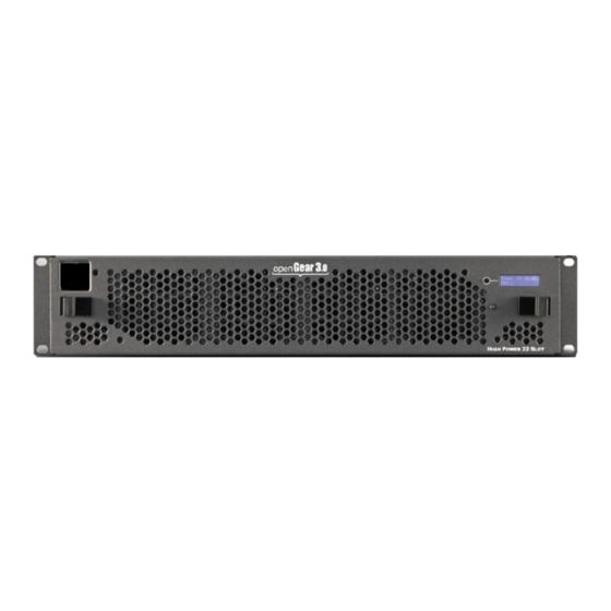
AG 2600 – User Manual Installation Carefully unpack the AG 2600 card and inspect it for any signs of damage. Do not insert the card into the openGear frame if any damage is evident, and if so, please contact Sencore. - Page 15 AG 2600 – User Manual Figure 2: View of card edge controls and LEDs Button Controls There are two button controls available on the AG 2600: • Boot to Recovery Image: If the card becomes corrupted, the user can remove the card from the slot and then reinsert the card while pressing and holding this button to boot to the recovery image.
-
Page 16: Backplane
AG 2600 – User Manual Backplane Each AG 2600 card comes paired with a compatible backplane. Figure 3 shows the backplane for an AG 2600 card with the DVB-S2 input option. Figure 3: Backplane with DVB-S2 Input Option Maintenance The AG 2600 is virtually a maintenance-free piece of equipment. There are no user serviceable parts on the card. - Page 17 Figure 4 shows the startup DashBoard screen. DashBoard has discovered an accessible frame. Note the “Sencore 4800A Frame1” icon near the top of the Basic Tree View pane. Clicking on the triangle ( ) symbol next to the frame name will display the available cards in the frame.
- Page 18 LED icon will give a tooltip style summary of status. Clicking on the triangle ( ) symbol next to the AG 2600 card will display the “Configuration” and “Web Interface” selections for that card (see Figure 6).
- Page 19 Figure 6: Configuration and Web Interface in Basic Tree View Network setup using DashBoard Double clicking “Configuration” will launch the setting and status window panes for the AG 2600 card shown in Figure 7. Figure 7: Configuration Page 19 (77)
- Page 20 Follow the following steps to obtain an IP address using DHCP: 1) In the setting pane, change ‘Mode’ to “DHCP. 2) Click ‘Apply Network Setting’. Note: It may take up to a minute for the AG 2600 to obtain an IP address. Page 20 (77)
-
Page 21: Section 3 Operating The Web Interface
AG 2600 – User Manual Section 3 Operating the Web Interface Introduction This section includes the following topics: AG 2600 Web Interface Overview ................22 Main Panel ......................... 24 Admin Panel ......................45 Reporting Panel ......................58 About Panel ....................... 62... -
Page 22: Ag 2600 Web Interface Overview
Logging into the AG 2600 Web Interface Once an IP address is set, each of the cards can be independently controlled via the web interface. To open the AG 2600 web interface use one of the following supported browsers and navigate to the card’s IP address: •... -
Page 23: Drag And Drop Menus
Drag and Drop Menus Certain menus in the AG 2600 allow the user to drag and drop items to auto populate fields. Conditional Access is an example of a menu that drag and drop can be used. In the example below a service in the transport stream view on the right hand side of the window is selected and dragged over to auto populate the Service and PIDs in the Conditional Access section. -
Page 24: Main Panel
AG 2600 – User Manual Main Panel The Main panel of the AG 2600 web interface is used to configure the unit to route an input to an output. When configuring the AG 2600 the user begins at the top of the menu and works down. - Page 25 Manual Only: the unit will not switch inputs automatically. The user must manually TS Sync Loss switch inputs. TS Sync Loss: the AG 2600 will switch from the primary to the backup input if the primary stream loses synchronization for the duration of the Switchover Interval.
-
Page 26: Configuring Asi Input
Backup Input or vice versa. Configuring ASI Input This menu allows the user to either Enable or Disable the ASI Input on the AG 2600 as well as set the Null Stripped setting, as shown in Figure 11. No other configuration is necessary for the ASI Input. - Page 27 AG 2600 – User Manual Figure 12: MPEG/IP Input Configuration Menu Setting Range Description Receive Enabled This setting allows the user to enable or disable these input stream settings. Disabled Physical Port 1 The physical connector on the MPEG/IP Connector card that will be used to receive the input.
- Page 28 This is the only setting required to receive a unicast stream. Enabled Enabling FEC (Forward Error Correction) tells the AG 2600 to look at Destination Port Disabled +2 and Destination Port +4 for a SMPTE 2022 FEC Matrix.
-
Page 29: Configuring Dvb-S/S2 Input
AG 2600 – User Manual that period will be logged. Selecting Manual will only clear the statistics by hitting the refresh button. Reset Interval 5-65535 Interval in which the Auto option will reset (min) and log the statistics displayed on the main... - Page 30 AG 2600 – User Manual Figure 13: DVB-S2 Configuration Menu Setting Range Description Port Enabled This setting allows the user to enable or disable this reception port. Disabled Mode DVB-S This setting allows the user to choose between DVB-S or DVB-S2 modulation DVB-S2 schemes.
-
Page 31: Configuring 8Vsb/Qam Input
Scrambling. In order to receive the stream, enter the value of the incoming signals PL Scrambling code. LNB Power The AG 2600 has the ability to provide the necessary voltage to power an LNB. Select 13 VDC the correct voltage to supply to the LNB. -
Page 32: Configuring Dvb-T2/C2/Isdb-T Input
AG 2600 – User Manual Setting Range Description Receive Enabled This setting allows the user to enable or disable this reception port. Disabled Mode 8VSB This setting allows the user to choose between 8VSB or QAM modulation 64-QAMB schemes. 256-QAMB... - Page 33 AG 2600 – User Manual Setting Range Description Recieve Enabled This setting allows the user to enable or disable this reception port. Disabled Mode DVB-T This setting allows the user to choose between DVB-T/T2/C/C2 or ISDB-T DVB-T2 modulation schemes. DVB-C...
-
Page 34: Configuring Dvb-Ci Descrambling
Low MER Alarm will be triggered in dB. Configuring DVB-CI Descrambling This section will describe how to configure DVB-CI descrambling in the AG 2600 (if equipped). First, the user will need to configure the CAM slots. Once this is complete the user can configure which services or PIDs to descramble. - Page 35 Configuring DVB-CI Slots This menu allows the user configure the DVB-CI slots in the AG 2600 as shown in Figure 14. The AG 2600 has two DVB-CI slots, a left and right, where CAM Modules can be inserted. Both slots are individually configurable.
-
Page 36: Configuring Biss Descrambling
Figure 15: DVB-CI Service Descrambling Menu Configuring BISS Descrambling This section will describe how to configure BISS descrambling in the AG 2600. There are two types of BISS descrambling. In “Descramble All PIDs” mode, the user simply configures a BISS key set and selects it from the drop down. - Page 37 AG 2600 – User Manual 3.2.8.1 Configuring BISS Keys This menu allows the user to configure BISS descrambling, as shown in Error! Reference source not found.. 12 unique BISS keys can be entered. If the BISS mode is set to Mode E a icon will appear next to Mode E Injected ID.
- Page 38 This menu (as shown in Figure 17) allows the user to select the services the AG 2600 will descramble using the BISS keys configured in Section 3.2.8.1. These options are applicable only if Operation Mode in the BISS settings is set to Descramble Selected Services (Refer to Section 3.2.8.1).
-
Page 39: Pid Filter
AG 2600 – User Manual PID Filter If the PID/Service Filter license is enabled, the following menus and options will be available for configuration. PID filtering will allow the user to create a new output TS by selecting and dragging one or more services/PIDs from the incoming transport stream into the Selected Services/Pids box or use the currently decoded stream. -
Page 40: Configuring Asi Output
AG 2600 – User Manual Configuring ASI Output This menu (Figure 18) allows the user to configure the ASI output of the AG 2600. When enabled this output acts as an active loop output of the active input. For example, if the DVB-S/S2 input card is the current active input the ASI output port will output a demodulated signal of the satellite input. - Page 41 AG 2600 – User Manual Figure 19: MPEG/IP Transmit Configuration Menu Setting Range Description Transmit Enabled Enable or disable the MPEG/IP transmit group. Disabled Source Unmodified Input Unmodified Input will pass the incoming TS to the output without applying any BISS or DVB-CI Descrambled decryption.
-
Page 42: Configuring The Mpeg/Ip Mpe Outputs
>1030 and an even number Source Port 0 - 65535 This is the port used by the AG 2600 to transmit the MPEG/IP stream. TS Packets Per The number of TS packets that are contained IP Packet with a single IP packet. - Page 43 AG 2600 – User Manual Setting Range Description Transmit Enabled Enable or disable transmission of de-encapsulated MPE data. Disabled Physical Port 1 The physical connector on the MPEG/IP card that Connector will be used to transmit the MPE data. Port 2...
-
Page 44: Viewing Psip Information
AG 2600 – User Manual Viewing PSIP Information To view the PSIP information for the applied TS, select the View PSI Tables button located on the right hand side of the Inputs section. This will open a new window that displays all of the PSIP information for the applied TS. -
Page 45: Admin Panel
AG 2600 – User Manual Admin Panel Figure 20: Admin tab To access the Admin Control Panel, click on the tab. This menu allows the user to control many aspects of the AG 2600. Page 45 (77) -
Page 46: Changing Unit Password
Profiles can be saved locally, renamed and saved to external storage to be used on other AG 2600s with the same hardware, licensing, and software version. Profiles can be used to quickly and easily change the configuration of an AG 2600 to suit different turnaround requirements. -
Page 47: General Settings
The AG 2600 can be assigned an alias which is displayed in the upper right hand corner of the web interface as shown in Figure 22. The alias can help define which AG 2600 the operator is currently logged into. The BISS-E Injected ID for BISS Mode E can also be protected from being accidently changed. -
Page 48: Unit Network Configuration
Configuration section. Domain name servers can be configured on the AG clicking the button. IP address and web address entries are accepted as Nameserver addresses. If the AG 2600 contains a 26127 option card the unit can be configured to have an optional 2 control port. -
Page 49: Mpeg/Ip Network Configuration
This is the Gateway address assigned to the XXX.XXX.XXX.XXX management port. The 2nd management port of the AG 2600 can be configured from the web interface. To make changes to which port is the 2nd management port click, the configure control ports button under the Unit Network Configuration section. -
Page 50: Licensing
128.0.0.0 - 191.255.0.0 192.0.1.0 - 223.255.255.0 Licensing Certain features of the AG 2600 require licenses in order to be functional. The interface displays all licenses available as well as the following status: • License Locked or Unlocked • License is Supported or Unsupported by the installed hardware If licenses need to be applied to the AG 2600 click button. -
Page 51: Date/Time
AG 2600 – User Manual Figure 25: License Key Date/Time The AG 2600 can be set to synchronize with an NTP server or a manual data and time can be defined by the user. Click the button to configure the date and time as shown in Figure 26. These values are used to timestamp entries in the Alarm and Event logs under the Reporting tab. -
Page 52: Configuring Snmp
Figure 27. Figure 27: SNMP Community Configuration Menu 3.3.8.2 SNMP Trap Managers The SNMP trap managers are recipients of SNMP traps sent from AG 2600. The following menu allows the user to configure the recipient’s IP addresses. remove recipients... - Page 53 IP address. 3.3.8.3 Download SNMP MIB Files The AG 2600 stores the SNMP MIB files for the currently installed version of software on the unit. These files can be downloaded directly from the AG 2600 by clicking on the button.
-
Page 54: Syslog
AG 2600 – User Manual Figure 29: Available MIBs Syslog The AG 2600 can be configured to send error and event logs formatted in the syslog protocol to a remote user specified Syslog server. Figure 30: Syslog Configuration Menu Action... -
Page 55: In-Band Control
The In-Band Control is used to change settings and receive updates from data within a PID in the incoming TS, as injected by the Sencore CMD 4000 In-band Control Server. The menu in Figure 31 allows the user to configure the In-Band Control settings. - Page 56 3.3.11.2 Rollback Software Updates The AG 2600 is capable of reverting back to a previous version of software using the Rollback feature. The AG 2600 maintains two separate software images; one is the most current version of software with all current settings and the other is the previous version of software with all settings.
-
Page 57: Reboot Unit
Reboot Unit The AG 2600 can be rebooted from the web interface. In order to perform a reboot click the button. The AG 2600 will prompt the user to confirm the reboot. -
Page 58: Reporting Panel
Reporting Panel Figure 34: Error Reporting Page tab in the AG 2600 contains logs for active alarms currently affecting the unit and an event log as shown in Figure 34. The active alarms are updated periodically in order to reflect the real-time state of the unit. Once an error is cleared it will be cleared from the active alarms window. -
Page 59: Event Logs
AG 2600 – User Manual Figure 35: Active Alarms Title Description State This column displays the nature of the alarm. The icon means the log entry is informational and is not an error. The icon means the log entry is an active alarm. - Page 60 AG 2600 – User Manual Figure 36: Condition and Event Log Title Description Severity This column displays the nature of the alarm. The icon means the log entry is informational and is not an error. The icon means the log entry is an active alarm.
-
Page 61: Configuring The Logs
AG 2600. The tab allows the user to configure the events reported by the AG 2600. Each column and its function are described below. A user configured time offset can also be applied to allow viewing the logs in a local time zone. -
Page 62: About Panel
AG 2600 – User Manual Alarm This column is only available in the tab This option allows the user to enable or disable this alarm in the Active Alarms log. If checked the alarm will be displayed in the Active Alarms log if raised. If this box is unchecked this error will be hidden. -
Page 63: Section 4 Appendices
AG 2600 – User Manual Section 4 Appendices Introduction This section includes the following appendices: – Acronyms and Glossary ............ 64 – Error and Event List ............67 – Specifications ..............69 – Open Source Software ............74 – Warranty ................76 –... -
Page 64: Acronyms And Glossary
AG 2600 – User Manual – Acronyms and Glossary 8VSB: Vestigial sideband modulation with 8 discrete amplitude levels. 16VSB: Vestigial sideband modulation with 16 discrete amplitude levels. AAC: Advanced Audio Coding AC-3: Also known as Dolby Digital AES: Audio Engineering Society... - Page 65 AG 2600 – User Manual High level: A range of allowed picture parameters defined by the MPEG-2 video coding specification which corresponds to high definition television. I/O: Input/Output IP: Internet Protocol Kbps: 1000 bit per second LED: Light Emitting Diode...
- Page 66 AG 2600 – User Manual RO: Read Only RPM: Revolutions Per Minute RRT: Rating Region Table RS-232: Recommended Standard. A standard for serial binary data interconnection. RU: Rack Unit RW: Read/Write SD: Standard Definition SDI: Serial Digital Interface SFP: Small Form-Factor Pluggable...
-
Page 67: Error And Event List
Service that BISS key is assigned to descramble is not present in the incoming stream. Backup Input Active Primary input is currently in a failed condition and the AG 2600 Condition has failed over to the Backup input. Bitrate Exceeded Error Total incoming transport stream bitrate has exceeded 213 Mbps. - Page 68 The AG 2600 has detected that the transport stream error indicator is present on the active input. Transport Stream Not The AG 2600 has detected that the transport stream from the Present active input is no longer present. TS Sync Loss Transport stream sync for input component is not detected.
-
Page 69: Specifications
AG 2600 – User Manual – Specifications AG 2600 – Base Unit Includes – Backplane System – Configurations Allows: Single turnaround card with an input option. Rear Panel: Fixed inputs and outputs with one option input. Option input not field upgradeable. - Page 70 AG 2600 – User Manual Packet Sizes Input:188 and 204 bytes Output: 188 bytes Modes Supported: Burst, Byte and Inverted DVB-CI Descrambling Module Option CAM Decryption – General – Compatibility Standard: DVB-CI EN 50221 Number of CAM Slots: Auto CAM insertion/removal...
- Page 71 AG 2600 – User Manual 4≤D≤20 Annex B Multicast Filtering: Filters based on IP address Buffer size: 1 - 4000 KB, or 1-4000ms, user configurable 0.25 – 200 Mb/s Bitrate Range: Packets/IP Frame: 1-7 MPEG Packets/IP Frame IGMP Compatibility: Version 2 and 3 Transmit –...
-
Page 72: 8Vsb/Qam Input Module Option
AG 2600 – User Manual ± 4 MHz in Wide mode (with SR 5 ≤ 6 MSps) ± 5 MHz in Wide mode (with SR ≥ 6 MSps) Standard / Wide modes user selectable Input RF Spectrum: Normal/Inverted Auto Detect... - Page 73 AG 2600 – User Manual Sensitivity: -34dBmV to + 40dBmV (A74 Compliant) Modulation: 8VSB, QAM-B MER: Range: 0dB to 40dB Accuracy: +/- 2dB Low Limit Flag: User Defined RF Level: Range: -34dBmV to +40dBmV Accuracy: +/- 5dBmV Low Limit Flag: User Defined QAM –...
-
Page 74: Open Source Software
AG 2600 – User Manual – Open Source Software The AG 2600 includes: Package Version License Copyright AT32 UC3B Software 1.7.0 2009, Atmel Corporation Framework BusyBox 1.20.1 GPL Version 2, June 1991 Erik Anderson, et. al. dfu-programmer 0.5.2 GPL Version 2, June 1991... - Page 75 AG 2600 – User Manual Spawn-FCGI 1.6.3 Jan Kneschke, Stefan Bahler TCLAP 1.2.0 2003 Michael E Smoot U-Boot 2009.11.1 GPL Version 2, June 1991 Wolfgane Denk, et. al. USB-Utils 0.86 GPL Version 2, June 1991 Thomas Sailer, Johannes Erdfelt, David Brownell, Zlib 1.2.7...
-
Page 76: Warranty
– Support and Contact Information Returning Products for Service or Calibration The AG 2600 it is necessary to return a product for repair or calibration. In order to expedite this process please carefully read the instructions below. RMA Number Before any product can be returned for service or calibration, an RMA number must be obtained. - Page 77 Sencore Inc. 3200 Sencore Drive Sioux Falls, SD 57107 USA www.sencore.com Copyright © 2017 Sencore Inc. 1.605.978.4600...
Need help?
Do you have a question about the AG 2600 and is the answer not in the manual?
Questions and answers