
Related Manuals for Axminster Trade AT305SB


Summary of Contents for Axminster Trade AT305SB
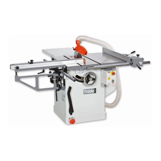
- Page 1 230V Code 700158 415V Code 600807 Original Instructions AT305SB 305mm Saw Bench AT: 11/10/2021 BOOK VERSION: 02...
- Page 2 EN 60204-1:1997 EN ISO 13855 Saw Bench Type Model AT305SB and conforms to the machinery example for which the EC Type-Examination Certificate No AN 50149963 has been issued by Union-one Machinery Co., Ltd. Signed at: No. 30-2 Lane 70, Sec. 1, Hsing-Lung Rd. 411 TaipingCity, Taichung Taiwan and complies with the relevant essential health and safety requirements.
-
Page 3: Table Of Contents
Table of Contents Table of Contents............................Warnings ............................... Specifications ..............................Shipping Contents............................Unpacking..............................Cleaning ..............................Contents of the Shipping Container ......................Assembly............................... Motor Cover............................... Handwheel Assembly ..........................Miter Gauge and Fence Storage Hooks....................Extension Wing............................Blade Installation/Replacement....................... Riving Knife and Guard Installation ......................Mounting Rails &... - Page 4 1. Read and understand the entire owner's manual before attempting assembly or operation. 2. Read and understand the warnings posted on the machine and in this manual. Failure to comply with all of these warnings may cause serious injury. 3. Replace the warning labels if they become obscured or removed. 4.
- Page 5 19. Keep visitors a safe distance from the work area. Keep children away. 20. Make your workshop child proof with padlocks, master switches or by removing safety keys. 21. Give your work undivided attention. Looking around, carrying on a conversation and “horse-play” are careless acts that can result in serious injury.
-
Page 6: Shipping Contents
Shipping Contents Unpacking Remove box and wood crating completely from around saw. Check for shipping damage. Report any damage immediately to your distributor and shipping agent. Do not discard any shipping material until the Table Saw is assembled and running properly. Compare the contents of your container with the parts lists in the next two pages to make sure all parts are intact. - Page 7 Specification Model AT305SB Code 700158 Rating Trade Power 2.2kW (230V) Plug Fitted UK 16A Blade Dia/Bore 305 mm/30 mm Blade Tilt 0° - 45° Max Depth of Cut @ 45˚ 72 mm Max Depth of Cut @ 90˚ 102 mm...
-
Page 10: Extension Wing
Extension Wing Referring to Figures 4 and 5: Hardware: (6) 7/16”x1-1/2” Hex Cap Bolts, (6) 7/16” Lock Washers, (6) 7/16” Flat Washers & (2) Extension Tables Tools: 17mm Wrench, Straight Edge 1. Attach the left extension wing (A) to the table (B) with three each hex cap screws (E), lock washers (F) and flat washers (G). -
Page 11: Riving Knife And Guard Installation
Riving Knife and Guard Installation Description Referring to Figure 7: The complete riving knife and guard assembly is shown in A. Installation Referring to Figure 8: 1. Set the saw blade to the 90 degree position and raise it all the way (refer to Handwheel Adjustments on page 13). -
Page 14: Riving Knife Adjustment
Riving Knife Adjustment Lateral alignment The saw blade and riving knife must be in line as close possible with each other (lateral alignment) for the prevention of kickback. Upon initial blade guard and riving knife installation no further adjustment should be necessary. Alignment should be checked and adjusted, if required, after each blade change. -
Page 15: Blade Alignment
4. Tighten the socket head flat screws ( (E). 5. Reinsert the riving knife; tighten the lock handle (A, Fig. 14) and check that the saw blade/knife gap is between 3 - 8mm (Figure 16). Note: Attempt to make the gaps as even as possible. -
Page 16: Adjusting 45 And 90 Positive Stops
Adjusting 45 and 90 Positive Stops The stops have been adjusted at the factory. After a period of use, or, after moving the saw to another location, the stops may no longer be set properly. To check and adjust the stops: Tools: 12mm wrench, combination square 1. -
Page 17: Changing The Belt
Changing the Belt Make all machine adjustments or maintenance with the machine unplugged from the power source. Failure to comply may cause serious injury! Referring to Figure 22: 1. Disconnect the machine from the power source, unplug. 2. Lower the blade to its lowest point. 3. -
Page 18: Troubleshooting
Troubleshooting Trouble Possible Cause Solution Overload tripped Allow motor to cool and reset by pushing off switch Saw stops or will Saw unplugged from wall or motor Check all plug connections not start Fuse blown or circuit breaker tripped Replace fuse or reset circuit breaker Cord damaged Replace cord Stops not adjusted correctly... - Page 20 Table and Cabinet Assembly(Right tilt) lndex Part Description Size Qty. 1………… UOTS10-1…………….…… Lock Knob………………. ……………..…1 2………… UOTS10-2.………………… Miter Gauge Body.……… ……………..…1 3………… UOTS10-3.………………… Hex Nut………………….. M5…………. .…3 4………… UOTS10-4.………………… Pointer…………………… ……………..…1 5………… UOTS10-5.………………… Stop Link………………... ……………..…1 6…………...
- Page 21 Table and Cabinet Assembly(Right tilt) lndex Part Description Size Qty. 28……….. UOTS10-28…..……………. Tilt Scale…………………… ……………..…1 29……….. UOTS10-29…..……………. Logo Lable………………… ……………..…1 30……….. TSCE10-30………………..Power Cord………………... ……….……. .…1 …………. TSCE12-30…………..…..… Power Cord………………... ……….……. .…1 31……….. UOTS10-31……………….… Carriage Bolt……………… 1/4” 3/4”..… .…4 32………..
- Page 22 Table and Cabinet Assembly(Right tilt) lndex Part Description Size Qty. 54……….. 901M06016…………………. Hex Socket Head Screw.…. M6 16……..…2 3/16 1/2…… .…2 55……….. 906316012…………………… Screw…………………….. 56……….. S12200015…………………... Foot Stop Switch…………... ……………..…1 57……….. 914M051001………………… Flat Washer………………... M5…………. .…2...
-
Page 24: Motor And Trunnion Assembly
Motor and Trunnion Assembly lndex Part Description Size Qty. 101……… UOTS10-101……………….. Arbor Nut……………..… ……………..…1 …………. UOTS12-101……………….. Arbor Nut……………….. ……………..…1 102……… UOTS10-102……………….. Arbor Flange…………..…..…………. .…1 ….……… TSCE12-102……………..…. Arbor Flange……………. ……………..…1 103……… UOTS10-103……………….. Saw Blade(Optional)…..10”(254mm) .…1 …….…… UOTS12-103………………... Saw Blade(Optional)……... - Page 31 Rip Fence Assembly lndex Part Description Size Qty. 1………... CE12F-1……………………. Rip Fence Body………… …………….. .…1 2………... CE12F-2……………………. Clamping Block………..……………. .…1 3………... CE12F-3……………………. Nylon Nut……………….. M10………. .…1 4………... CE12F-4……………………. Flat Washer…………….. M10………. .…1 5………... CE12F-5……………………. Knob…………………….. ……………. .…1 6………... CE12F-6……………………. Fiber Washer……………. M10………. .…1 7………...
- Page 32 Rip Fence Assembly lndex Part Description Size Qty. 33………. CE12F-33…………………… Ball Bearing…………….. 6200zz……... ….2 34………. CE12F-34…………………… Stop Profile……………… …………….. ….1 35……….. CE12F-35…………………… Sticker…………………… …………….. ….1...
- Page 34 Sliding Table Assembly (Optional) lndex Part Description Size Qty. 1………… 231-4101……………………... Hex Socket Cap Screw… 3/8”x1”…..…2 2………… 231-4102……………………... Guide Shaft……………… ……………..…1 3………… 231-4103……………………... Guide Rail Bracket…..…..…………. .…2 4………… 231-4104……………………... Plate……………………… ……………..…1 5………… 231-4105……………………... Hex Nut………….……... M8………..…1 6…………...
- Page 35 Sliding Table Assembly (Optional) lndex Part Description Size Qty. 34……….. 231-41034……………………. Round Head Screw………... M4x10…….. .…2 35……….. 231-41035……………………. Nylon Nut………………….. 5/16”…….… .…1 36……….. 231-41036……………………. Plate ………………………... …………..… .…1 37……….. 231-41037……………………. Work Table………………… …………..… .…1 38……….. 231-41038……………………. Cross Shaft………………… ……………..…1 39………..
- Page 37 The Axminster guarantee Buy with confidence from Axminster! So sure are we of the quality, we cover all parts and labour free of charge for three years! For more information visit axminstertools.com/3years The packaging is suitable for recycling. Please dispose of it in a responsible manner. EU Countries Only Do not dispose of electric tools together with household waste material.
Need help?
Do you have a question about the AT305SB and is the answer not in the manual?
Questions and answers