
Related Manuals for Axminster Trade AT254LTS


Summary of Contents for Axminster Trade AT254LTS
- Page 1 Code 105573 Original Instructions AT254LTS 254mm Table Saw AT&M: 01/05/2019 BOOK REF : 106214...
- Page 2 EN 1870-19:2013 EN 60204-1:2006+A1+AC Type Table Saw Model AT254LTS and conforms to the machinery example for which the EC Type-Examination Certificate No BM 50416470 has been issued by Harvey Industries Co., Ltd. Signed at: 01 Building, No.68 Suyuan Road, Jiangning Economic & Technological Development Zone,...
-
Page 3: Table Of Contents
TABLE OF CONTENTS INTRODUCTION SECTION 1 SAFETY INFORMATION------------------------------------------------------4 SECTION 2 ELECTRICAL REQUIREMENTS------------------------------------------12 SECTION 3 PRODUCT SPECIFICATIONS --------------------------------------------13 SECTION 4 FEATURE IDENTIFICATION -----------------------------------------------14 SECTION 5 UNPACKING & INVENTORY-----------------------------------------------15 SECTION 6 ASSEMBLY----------------------------------------------------------------------16 SECTION 7 ADJUSTMENTS---------------------------------------------------------------21 SECTION 8 OPERATIONS------------------------------------------------------------------24 SECTION 9 SAFETY ACCESSORIES---------------------------------------------------26 SECTION 10 MAINTENANCE---------------------------------------------------------------27 SECTION 11 TROUBLE SHOOTING GUIDE--------------------------------------------28 SECTION 12 WIRING DIAGRAM-----------------------------------------------------------29... - Page 4 SAFETY RULES FOR YOUR OWN SAFETY, READ INSTRUCTION MANUAL BEFORE OPERATING THIS MACHINE. The purpose of safety symbols is to attract your attention to possible hazardous conditions. This manual uses a series of symbols and signal words intended to convey the level of importance of the safety messages.
- Page 5 10. ALWAYS WEAR SAFETY GLASSES. Everyday eyeglasses only have impact resistant lenses, there are NOT safety glasses. Also use a face or dust mask if cutting operation is dusty. 11. HEARING PROTECTION. Always wear hearing protection when operating or observing loud machinery. Extended exposure to this noise without hearing protection can cause permanent hearing loss.
- Page 6 12. PROVIDE ADEQUATE SUPPORT. To the rear and sides of the table saw for wide or long workpieces. 13. AVOID KICKBACKS. Avoid kickbacks (work thrown back towards you) by keeping the blade sharp, by keeping the rip fence parallel to the saw blade, by keeping the splitter and anti-kickback fingers and guard in place and operating, by not releasing work before it is pushed all the way past the saw blade, and by not ripping work that is twisted or warped or does not have a straight edge to guide along the fence.
- Page 7 Nonperformance of this caution can cause a small sized injury or machine damage. Basic safety requirements Never touch the low voltage system on the electric control panels, motors and terminal boards. Every of mentioned unit is indicated with a shield. -Before connecting machine to mains: Make sure that all safety parts are in active position and check up their functioning.
- Page 8 Safety regulations for machine operator -Do not start up the machine before having got up the content of this manual. -Check up whether electric cables are not damaged so as an electric current fading would not cause an injury (electric shock). -Check up regularly whether safety coverings are properly mounted and if they are undamaged.
- Page 9 Safety regulations for working place - Ensure always sufficient working space and free access to the machine and its peripheral device. - Place the tools and other obstacles at a place for this intended and remote from the machine. - Ensure sufficient lighting in working space that will not throw shadows or cause a stroboscopic effect. Hygienic norms indicate 500 lx for minimal lighting for safe and quality work.
- Page 10 Refer to instruction manual/booklet To signify that the instruction manual/ booklet must be read. Disconnect mains plug from electrical outlet To signify that the mains plug must be disconnected from electrical outlet in case of maintenance, malfunction or when left unattended. Wear opaque eye protection To signify that opaque eye protection must be worn.
- Page 11 parts and hardware from the inside of the machine and unbolt the machine from the pallet. ----- FLOOR: This tool distributes a large amount of weight over a small area. Make certain that the floor is capable of supporting both the weight of the machine and the operator. The floor should also be a level surface. If the unit wobbles or rocks once in place, be sure to eliminate by using shims.
-
Page 12: Electrical Requirements
ELECTRICAL REQUIREMENTS GROUNDING This cabinet hybrid saw must be grounded, if it should malfunction or breakdown, grounding provides a path of least resistance for electric current, which reduces the risk of electric shock. To maintain proper grounding of your table saw, do not remove or alter the grounding prong in any manner. WARNING: If out let is not properly grounded, this cabinet hybrid saw can cause electrical shock, particularly when used in damp locations. -
Page 13: Product Specifications
PRODUCT SPECIFICATIONS Item Specification Weight 175kg Product Length/Width/Height 1340x1650x1200mm Dimensions Foot Print(Length/Width) 514x498mm Electrical Switch Switch With Overload Protection Type TEFC Capacitor Start Induction Horsepower 1.65kW, S6 40% Voltage 230V Phase Single Motor Amps Speed 2900/min Cycle 50HZ Power Transfer V-Ribbed Belt Drive Maximum Blade Diameter 254mm... -
Page 14: Feature Identification
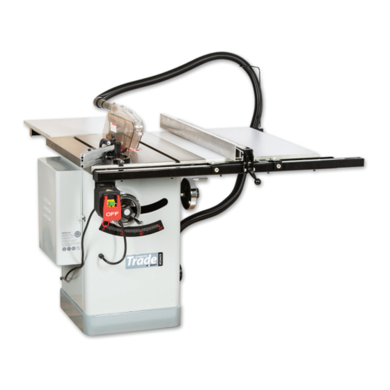
FEATURE IDENTIFICATION IDENTIFICATION 1. Rear Outfeed Table; 2. Mitre Gauge; 3. Blade Guard; 4. Fence; 5. Rear rail; 6. Right Hand Extension Table; 7. Front rail; 8. Scale; 9. Front Rail Tube; 10. Fence Lock Handle; 11. Blade Tilt Handwheel; 12. -
Page 15: Unpacking & Inventory
UNPACKING & INVENTORY WARNING: This machine and its components are very heavy. Get lifting help or use power lifting equipment such as a forklift to move heavy items. WARNING: SUFFOCATION HAZARD! Immediately discard all plastic bags and packing materials to eliminate choking/suffocation hazards for children and animals. -
Page 16: Assembly
ASSEMBLY Motor Cover Install the door by inserting the pins of the door into the two hinge socket on the cabinet. (See Figure 1) Figure 1: Motor Cover Install Extension Table 1. Attach a right hand extension table to the right or left side of the table using three each Hex Head Bolt 10 x 25mm, 10mm lock washers and 10mm flat washers. -
Page 17: Rear Outfeed Table
Rails, tables and fence. 1. Install the front rail using 8mm countersunk 2. Install the rear rail using 8mm Hex socket 3. Install the fence mounting rail to the front bolts, washers and nuts. Tighten the bolts bolts, washers and nuts. Again, do not rail using 5 x 5mm Hex socket bolts and washers. - Page 18 9. Mount the rip fence to the front rail, and by using the adjusting screws “A” set the fence to be just above the main table body, and “B” to set the fence parallel to the blade. 10. Use this adjustment to set the fence rail 11.
- Page 19 Fence Place the Fence on the rails on the right hand side of the blade. (See Figure 6 ) Note: The cam foot must contacts the cam on the fence lock handle before you place the fence on the rail, otherwise the fence will not lock onto the rail tube.
- Page 20 Magnetic Switch Install the magnetic switch onto the bottom left hand side of the front rail using two M5-.8x 8 hex bolts, 5mm lock washers, and 5mmflat washers. (See Figure 8) Saw Blade 1. Remove blade guard assembly and table insert. 2.
- Page 21 Fence Scale 1. Slide the fence up against the blade and lock it in place. 2. Attach the front rail tape scale above the fence tube, making sure it is parallel with the tube and that the "0" end is directly under the red line on the pointer window (See Figure 13) 3.
- Page 22 The guard encloses the top of the blade to reduce the risk of accidental blade contact and contain flying chips or dust. The guard is designed to lift as the workpiece is pushed into the blade, remain in contact with the workpiece during the cut, then return to a resting position against the table when the cut is complete.
-
Page 23: Adjustments
ADJUSTMENTS CAUTION: For your convenience, the adjustments listed below have been performed at the factory and no further setup is required to operate your machine. However, because of the many variables involved with shipping, we recommend that you at least verify the following adjustments to ensure that the cutting you do with your new machine is safe and accurate. - Page 24 Table T-Slot To Blade Parallelism Your table saw will give the best results if the table T-slot and the rip fence are adjusted parallel to the blade. If either of these are not exactly parallel, your cuts and your Mounting Bolts finished work will be lower in quality, but more importantly, the risk of kickback will be increased.
- Page 25 WARNING: Miter Gauge Adjustments Make Sure The Power Cord Is Disconnected From The Power Source! 1. Slide the miter gauge into the T-slot on the table. Tensioning Belt 2. Loosen the miter gauge lock knob, pull out the 1. Lower the blade completely, open the motor cover. positive stop knob, then pivot the miter gauge body to 90°...
-
Page 26: Operations
OPERATIONS Plain sawing includes ripping and crosscutting, plus a few other standard operations of a fundamental nature. The following methods feature safety. As with all power tools there is a certain amount of hazard involved with the operation and use of the tool. Using the tool with the respect and caution demanded as far as safety precautions are concerned will considerably lessen the possibility of personal injury. - Page 27 Dado Cutting Installing A Dado Blade Dadoing is cutting a wide groove into a workpiece or 1..DISCONNECT THE SAW FROM POWER! cutting a rabbet along the edge of a workpiece. 2. Remove the table insert, the blade guard Commonly used in furniture joinery, a dado is a straight assembly or riving knife, and the saw blade.
-
Page 28: Section 9 Safety Accessories
SAFETY ACCESSORIES Push Sticks Push Blocks When used correctly, push sticks reduce the risk of When used correctly, a push block reduces the risk injury by keeping hands away from the blade while of injury by keeping hands away from the blade cutting. -
Page 29: Section 10 Maintenance
MAINTENANCE WARNING Always Disconnect Power To The Machine Before Performing Maintenance. Failure To Do This May Result In Serious Personal Injury. Cleaning Note: The following maintenance schedule assumes the saw is being used every day. Daily: Wipe down the table surface and grooves with a rust preventive. Clean the pitch and resin from the saw blade. - Page 30 TROUBLE SHOUTING GUIDE PROBLEM PROBABLE CAUSE SOLUTION Saw not plugged in. Plug in saw. Saw Will Not Start Fuse blown or circuit breaker tripped. Replace fuse or reset circuit breaker. Cord damaged. Have cord replaced by a certified electrician. Extension cord too light or too long. Replace with adequate size cord Feeding stock too fast.
-
Page 31: Section 12 Wiring Diagram
WIRING DIAGRAM ON/OFF SWITCH 250V 16A Line Load KEDU KJD17B 16A 220-240V Capacitor 200-240UF 250VAC Capacitor 40UF 450VAC 220V MOTOR WIRING DIAGRAM COLOR KEY Bk:Black Rd:Red Wt:White Gn:Green Yl:Yellow - 31 - Please Save This Manual For Future Reference... -
Page 32: Section 13 Parts List
PARTS LIST Table Saw Body Breakdown - 32 - Please Save This Manual For Future Reference... - Page 33 Table Saw Body Parts List PART# DESCRIPTION PART# DESCRIPTION STD Table Insert Button Head Screw M5x 12 Flat Head Screw M5 X 10 Plate Flat Head Screw M5x 20 Button Head Screw M5x 16 Main Table Hex Nut 8mm Motor Cover Angle Scale Tooth Washer 6mm Lock Nut 3mm...
- Page 34 Trunnion Assembly Breakdown - 34 - Please Save This Manual For Future Reference...
-
Page 35: Section 7 Adjustments
Trunnion Assembly Parts List PART# DESCRIPTION PART# DESCRIPTION Lock Nut M16 Arbor Nut Flat Washer 16mm Knurled Knob Cap Screw M8x 20 Splitter Adjust Block Lock Washer 8mm Spring Flat Washer(W) 8mm Spacer Motor Locking Pin Cap Screw M6x 16 Splitter Tighten Clip Lock Washer 6mm Cap Screw M6x 25... - Page 36 Power Switch 222-1 PART# DESCRIPTION PART# DESCRIPTION TAP SCREW M3.5 X 19 FLAT WASHER 4M POWER SWITCH KEDU KJD17B 230V CLAMP-ON TERMINAL RING 222-1 PADDLE SWITCH LOCKOUT PIN SWITCH BRACKET SWITCH BOX TAP SCREW M3.5 X 10 CIRCUIT BREAKER 16A 220V STRAIN RELIEF TYPE-3 M18-1.5 CIRCUIT BREAKER NUT M10-1.5 POWER CORD 14G 3W 72"...
- Page 37 Blade Guard Breakdown Please Save This Manual For Future Reference - 37 -...
- Page 38 Blade Guard Parts List PART# DESCRIPTION PART# DESCRIPTION Flat Head Screw M4x10 Splitter Guard Support 1 Shoulder Screw M6.5x25 Guard Support 2 Shoulder Screw M6.5x10 Stepped Nut M4 Right Guard Vacuum Cleaner Tap Screw M2.9x9.5 Left Guard Riving Knife Tap Screw M3.5x16 Hose Support Arm Spring Clamp Hex Nut M6-1...
- Page 39 Miter Gauge Breakdown PART# DESCRIPTION PART# DESCRIPTION 401A Miter Gauge Assembly Lock Washer 4mm Guide Bar Button Head Screw M4x 6 Angle Scale Miter Knob Rivet Flat Washer 4mm Set Screw M8x 6 Crosscut Fence Miter Ring Square Nut M6 Flat Head Screw M5x8 Flat Washer 6mm Miter Body Pivot Pin...
- Page 40 High/Low Fence Breakdown 512 507 PART# DESCRIPTION PART# DESCRIPTION Glide Pad Lock Nut 10mm Hex Nut 12mm Button Head Screw M5x 8 Set Screw M12x 15 Flat Washer 5mm Set Screw M12x10 Ruler X-Ray Film Hex Bolt M6x40 Fence Insert Cam Plate Set Screw M12x 30 Lock Nut 6mm...
- Page 41 Extension Table Breakdown PART# DESCRIPTION PART# DESCRIPTION End Cap Lock Washer 8mm Guide Tube Hex Nut 8mm Front Rail Rear Rail Scale Cap Screw M10x25 Flat Washer 6mm Flat Washer 10mm Lock Washer 6mm Cap Screw M8x35 Cap Screw M6x16 Flat Head Screw M8x35 Extension Board Flat Washer 8mm...
-
Page 42: Section 14 Warranty Information
WARRANTY INFORMATION LIMITED WARRANTY One year PROOF OF PURCHASE Please keep your dated proof of purchase for warranty and servicing purposes REPLACEMENT PARTS About replacement parts, Please use the 10 digit part numbers listed in this manual for all part orders where applicable. - Page 44 The Axminster guarantee is available on Craft, Trade, Engineer, Air Tools & CNC Technology Series machines Buy with confidence from Axminster! So sure are we of the quality, we cover all parts and labour free of charge for three years! For more information visit axminster.co.uk/3years The packaging is suitable for recycling.
Need help?
Do you have a question about the AT254LTS and is the answer not in the manual?
Questions and answers