Advertisement
Quick Links
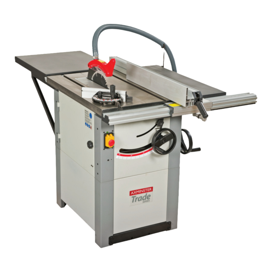
AW10BSB2,AW12BSB2
Saw Bench
AW10BSB2 Code 501196
AW12BSB2 Code 501197
Sliding Table Kit
AW10BSB2 AW12BSB2
Code: 951539
Table Extension Set
AW10BSB2 Code: 951538
AW12BSB2 Code: 951541
Saw Bench Package
AW10BSB2 Code: 718652
AW12BSB2 Code: 718653
Setup 1
Setup 2
AT&M: 03/04/2017
REF: 508304
Advertisement

Subscribe to Our Youtube Channel
Related Manuals for Axminster Trade AW10BSB2


Summary of Contents for Axminster Trade AW10BSB2
- Page 1 AW10BSB2 Code 501196 AW12BSB2 Code 501197 AW10BSB2,AW12BSB2 Sliding Table Kit Saw Bench AW10BSB2 AW12BSB2 Code: 951539 Table Extension Set Setup 1 Setup 2 AW10BSB2 Code: 951538 AW12BSB2 Code: 951541 Saw Bench Package AW10BSB2 Code: 718652 AW12BSB2 Code: 718653 AT&M: 03/04/2017...
- Page 2 Index of Contents Page Declaration of Conformity Parts Index 04-05-06 General Instructions for 230V Machines 06-07 Specification Initial Assembly Saw Body Assembly 09-10-11 Fitting Hand Wheels 11-12 Saw Guard Assembly 12-13-14 Mitre Fence Assembly Rip Fence Assembly 14-15 Micro-Adjuster Assembly Rip Fence Extension Kick-Plate Assembly 951538 10”...
- Page 3 Declaration of Conformity Copied from CE Certificate manufactured by Laizhou Fulin Machinery Co. is in compliance with the following standards or The undersigned, F. Nispel authorised by standardisation documents inaccordance with Laizhou Fulin Machinery Co., Ltd.No. 275 Wenquan Council Directives East Road Laizhou, Shandong 261400 P.R.
- Page 4 Parts Index Model Number: MJ2325D/MJ2330D 501196 10” and 501197 12” Saw Bench (Box 1 of 2) 1 off: Saw Table on upper chassis (with motor, table insert, saw blade & NVR Switch fitted) 2 off: Side Panels and Front & Back Panels 4 off: Lower Leg Columns 1 off: Side Table Extension 1 off: Dust Extraction Moulding 100mm...
- Page 5 Parts Index 501196 10” and 501197 12” Saw Bench (Box 2 of 2) 1 off: Rip Fence Assembly (partially assembled) 1 off: Rip Fence Extension 1 off: Short Rip Fence (front rail) 1 off: Short Rip Fence (back rail) Bag Containing: 2 off: ‘T’...
- Page 6 ‘unbreakable’ type that will resist damage on plug (AW10BSB2) and 16 Amp plug (AW12BSB2) with a site. Only use a 16 Amp plug, (AW10BSB2) and 16 Amp 3 core power cable. Before using the machine inspect plug (AW12BSB2) and make sure the cable clamp is the cable and the plug to make sure that neither are tightened securely.
- Page 7 General Instructions for 230V Machines UNDER NO CIRCUMSTANCES SHOULD CHILDREN BE ALLOWED IN WORK AREAS t is good practice to leave the machine unplugged being caught up in the rotating parts of the machine, until work is about to commence, also make sure likewise, consideration should be given to the removal to unplug the machine when it is not in use, or of rings and wristwatches, if these are liable to be a...
- Page 8 Specification Model AW10BSB2 AW12BSB2 Code 501196 501197 Rating Trade Trade Power 2.2kW 230V 1ph 3kW 230V 1ph Blade Dia/Bore 254 x 30mm 315 x 30mm Blade Tilt 0-45° 0-45° Max Depth of Cut @ 45˚ 60mm 75mm Max Depth of Cut @ 90˚...
- Page 9 Initial Assembly PLEASE RECYCLE ANY UNWANTED PACKAGING RESPONSIBLY Saw Body Assembly Having unpacked the boxes, put the parts and up finger tight at this time. (See fig 2) Locate the rear extention table (6), table support brackets (7) and 4 No. components where they are readily to hand.
- Page 10 Initial Assembly With easy open access, now is a good time to fit the Fig 5 dust extraction hose. Locate the hose (4A) and the two 125mm hose clips (16). Stretch the hose out to its full length. Slip the hose clips over the ends of the hose, fit the hose to the outlet on the saw box and the dust extraction moulding and tighten the hose clips to clamp them in place.
- Page 11 Initial Assembly When everything is tightened up, the machine can Fig 16 now be tipped over, towards its blind face until it is resting on the pallet with its legs on the floor. Lift the machine upright. (See figs 13-14) Fig 12 Side Extension Table Locate four M8 x 16mm hexhead bolts and washers.
- Page 12 Initial Assembly Fitting Hand Wheels Fig 20 Locate the two hand wheels (10). Remove the Hex screw and washer from both drive shafts and place aside. Insert a square key into each machined slot on the drive shafts and slide the hand wheels onto the shafts.
- Page 13 Initial Assembly Introduce the slot in the riving knife (14) over the two centre line bolts, behind the washers and nip the bolts to just hold the riving knife against the mounting plate. Set the riving knife so its close to the blade, (gap with in 8mm). Tighten the clamping bolts securely. (See figs 23-24) Replace the saw gullet.
- Page 14 Initial Assembly There is no requirement to remove the guard. The profile of the riving knife precludes the use of the saw for slotting or grooving, and the maximum depth of cut can be achieved with the guard in place. NOTE: The positioning of the extraction hose could be a nuisance if you are cutting big boards, in such a case it is better to remove the hosing from the guard, then there is less risk getting the workpiece snagged and perhaps ‘slewing’...
- Page 15 Initial Assembly Locate the capping plates for the front rail (24B) and using the self tapping screws (24C), secure in place. (See fig 35) Set the front rail in position, remembering that it must be slightly inside the front left hand edge of the main saw table, so that the sliding table does not collide with it. Tighten ONLY the 3 bolts in the main saw table.
- Page 16 Initial Assembly Rip Fence Extention tighten to clamp the extension in place. (See fig 46) Introduce the nose of the bar (12) into the required Locate the Rip Fence Extension (21), the two M6 x ‘T’ slot in the main table. (See fig 47) 70mm ‘T’...
- Page 17 Initial Assembly it almost home. The extension should be hanging WARNING!! THE EXTENSION TABLES approximately in its correct position held by the ARE VERY HEAVY YOU WILL REQUIRE A two bolts. Introduce and almost screw home the SECOND PERSION TO HELP! other two bolts and washers.
- Page 18 Initial Assembly First remove the rip fence assembly (20) and place 501196 10” and 501197 12” safely aside, loosen both rip fence rails (32-33) and Table Extension Kits (Box 2 of 2) slide them to the right. Undo the four M8 x 30mm Locate the long Rip Fence (front rail) (32) and (back hex bolts and remove the left table.
- Page 19 Initial Assembly Fig 56 Fig 60 Screw the threaded rubber foot (28) on to the end of the support leg (27), until it’s tight. (See fig 57) Unlock the caphead clamping bolt of the support leg and allow the inner section to slide through until the foot is resting on the floor.
- Page 20 Initial Assembly 951539 10” and 12” Sliding Table Kits (Box 1 of 2) and (Box 2 of 2) Mounting Bracket/Adjuster Block Assembly Locate and identify the mounting brackets (35) and bolts (39). Unscrew the caphead bolt in the height the height adjustor blocks (45). These are mounted adjustor block (45), see fig 64, until the recessed on the outside faces of the upper chassis legs.
- Page 21 Initial Assembly Fig 66 Fig 67 Screw the adjusting caphead bolt back Leave the brackets at approximately the through until it touches the lower face of same height. the mounting bracket. Slide Rail and Table Assembly Locate the slide rail assembly (40), orientate it so that the longest rail is at the top, and the channels etc., of the extrusion are underneath.
- Page 22 Initial Assembly Locate the sliding table assembly (38) and manoeuvre the bearing bogies onto the rails (40), slide the table onto the rails and position it safely within the boundary of the table. (See fig 73) Ensure that the initial setting of the slide rail assembly will not cause the sliding table (38) to collide with the main table (1).
- Page 23 Initial Assembly Lower the fence mounting (43) onto the rear quadrant NOTE: position the fence so the sacrificial plastic orange tongue is against the table to the right of the mounting. Position the fence so when it is pivoted it will not encroach into the saw slot. Lightly tighten the two caphead bolts on the fence mounting (43).
- Page 24 Setting the Machine Setting the Tables PLEASE ENSURE THAT BY NOW, THE SAW BENCH IS PLACED IN ITS WORKING LOCATION IN THE WORKSHOP. Place a long straight edge (as long as ext. table plus 2/3 metres main saw table min.) along one long edge of the rear table and along the main table.
- Page 25 Setting the Machine Fig 86 Fig 87 Place a level across the main and the Place a level in the horizontal position on sliding tables to check both are level the sliding table and adjust until it’s level Fig 88 Fig 89 Use the height adjusting blocks to adjust The mounting bracket (36) fixing bolts (A)
- Page 26 Setting the Machine Fig 91 Fig 92 Set the sliding table so that the front edge is inline with the front edge of the saw table. Place a long straight edge (a bit more than twice the width of the sliding table) along the front edges of the two tables.
- Page 27 Setting the Machines Setting the Angle Fence to the Saw Blade Raise the blade to its maximum height, check that the Mitre Angle Rear Quadrant. (See figs 95-96) This is upright to the table. Set the sliding table fence preset post is a small eccentric cam mounted on the to zero angle against the preset post.
- Page 28 Setting the Machine Tilt the blade fully over. Using a mitre square, set the angle of the saw to 45˚. Check that the index mark gives a corresponding reading against the scale. Adjust the pointer if necessary. Reset the blade upright, check that the angle scale reading is correct. (See figs 98-99) Fig 98 Fig 99 Tilt index scale...
- Page 29 Setting the Machine Setting the Mitre Fence Fit the small mitre fence (11) to the machine. Loosen Check that the angle is correct (and the lug is on the clamping handle (A). the correct side of the pin). Check that the indexing pointer gives the correct reading against the scale.
- Page 30 Setting the Machine Connect the machine to the mains supply, lift the switch shroud and give the machine a quick burst. i.e. On/Off. Check that everything is sound and feels O.K. (No knocking, scraping, belt squeal, rubbing etc.,) Give the machine a longer run, and ‘SLAP’ the Emergency switch shroud down. Check that this gives a fast and easy method of switching the machine off, without searching for the stop switch button.
- Page 31 Specific Instructions/Precautions for the Saw Bench the blade ensure that the push stick is to hand, foreign objects e.g. old nails, screws, small and you use it. stones etc embedded in the material you are about to cut. If necessary take a wire brush to Remember the emphasis of the push should the timber before working.
- Page 32 Illustration and Parts Description Extension lock 25. Micro Adjuster Assembly 1. Saw Bench 26. Extension Tables 2. Front and Side Panels 27. Table Support Leg 3. Lower Leg Columns 4. Dust Extraction Moulding 100mm 28. Threaded Rubber Foot 6. Extension Table 32.
- Page 33 Illustration and Parts Description Table Extensions Setup 1 Table Extensions Setup 2...
- Page 34 Illustration and Parts Description Hose support bracket Access door Rise and full tilt index scale Tilt control Rise and full hand wheel control handle NVR “ON” and “OFF” switch assembly Rise and fall control locking handle (1) Tilt angle lock (2) 23.
- Page 35 Changing the Saw Blade WARNING! DISCONNECT THE MACHINE FROM THE MAINS! Raise the saw blade to it’s highest point. Remove the saw blade guard. Remove the 5 screws that secure the table insert, place carefully aside and remove the table insert. (A) Using the spanner and the tommy bar provided, put the spanner onto the flats on the nut.
- Page 36 Changing the Saw Blade Tighten up the saw nut, using the tommy bar Give the machine a ‘quick’ burst check ( i.e. quick to hold the shaft steady. Check the riving knife ON-OFF) to ensure everything is O.K. If everything is is aligned with the saw blade, and correctly satisfactory, continue to use the machine.
- Page 37 Wiring Diagram...
- Page 38 Parts Breakdown/List DIAGRAM A...
- Page 39 Parts Breakdown/List DESCRIPTION A-22 Switch house Front panel A-23 Rubber washer of switch house Left frame A-24 Hexagon nut M5 Side panel A-25 Wire strain Real panel A-26 Externalteeth lock washer Right frame A-27 Earth-plate Left leg A-28 Cross recessed pan head screw M4X10 Front side board A-29 Washer 5...
- Page 40 Parts Breakdown/List DIAGRAM B Part 1...
- Page 41 Parts Breakdown/List DIAGRAM B Part 2...
- Page 42 Parts Breakdown/List DIAGRAM B Part 1 DESCRIPTION B-14 Left end cap for front rail Rear rail B-15 Front rail Step blot N8X25 B-16 Right end capfor front rail Cross recessed countersunk head screw B-17 Square nut M5 M5X6 B-18 Rack Insert B-19 External teeth washer 5...
- Page 43 Parts Breakdown/List DIAGRAM C DESCRIPTION C-11 Guide board Lock handle for miter gauge C-12 Cross recessed pan head screw M4x8 Large washer 8 C-13 Hexagon nut M4 Mitre gauge C-14 Scale Cross recessed pan head screw M5x10 C-15 Cross recessed countersunk head tapping scerw M5x10 Mitre gauge pointer C-16...
- Page 44 Parts Breakdown/List DIAGRAM D...
- Page 45 Parts Breakdown/List DESCRIPTION D-55 Thin nut M12 Blade nut M16((left-hand)( D-56 Height adjusting rod Outer blade washer D-58 Motor Blade D-59 Hexagon head bolt M8X40 A-blet D-60 Key 8X7X50 Pulley D-61 Hexagon socket set screw with Key( (A-type)( Flat point M6X9 Arbor shaft D-62 Hexagon socket set screw with...
- Page 46 Parts Breakdown/List DIAGRAM E DESCRIPTION E-22 Cross recessed pan head screw M5x10 Round head rhvetwhthsamall head ɸ3x7 E-23 Square nut M5 Hexagon nut M8 E-24 Small gear Washer 8 E-25 Gear rod Round head screw ɸ 3x13 E-26 Eccentric wheel Lock plate E-27 Gear rod frame...
- Page 47 Parts Breakdown/List DIAGRAM F DESCRIPTION F-14 Strip-shape nut F-15 End cap for guide rail Sliding table F-16 Hexagon socket cap head screw Long round rail M6X18 O-shape rubber ring ɸ20 F-17 Washer 6 Stop block F-18 Short round rail Cross recessed countersunk head screw M6X12 F-19 Angle bracket...
- Page 48 Parts Breakdown/List DIAGRAM G DESCRIPTION G-20 Strip-shape nut Self-locking handle M8X25 G-21 Knob-lever Stop block G-22 Eccentric lever Hexagon socket set screw M5x12 G-23 Stop board G-24 Circlip for shaft d=14 Washer 8 G-25 Holder rod Hexagon socket cap head screw M G-26 Spring 10x20...
- Page 49 Notes...
- Page 50 Notes...
- Page 51 Notes...
- Page 52 The Axminster guarantee is available on Hobby, Trade, Industrial, Engineer, Air Tools & CNC Technology Series machines It’s probably the most comprehensive FREE guarantee ever- buy with confidence from Axminster! So sure are we of the quality, we cover all parts and labour free of charge for three years! •...
Need help?
Do you have a question about the AW10BSB2 and is the answer not in the manual?
Questions and answers