Table of Contents
Advertisement
Quick Links
Solid-state Timer
H3FA
Please read and understand this catalog before purchasing the products. Please consult OMRON representative if you have any questions or
comments. Refer to "Warranty and Application Considerations" on page 12 and "Safety Precautions" on page 9.
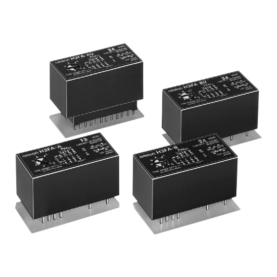
DIP Model Timer for PC Board Use Provides
Contact and Solid-state Output
• Four time ranges are selectable.
Models suffixed -@A@: 1 s, 10 s, 1 min, 10 min.
Models suffixed -@B@: 6 s, 60 s, 6 min, 60 min.
• Timer operation may also be controlled through an external
variable resistor.
• Timer can be cleaned while mounted on a PC Board with the
sealing tape affixed.
• Twenty-four-pin IC socket can be used for mounting the Timer.
• Mountable on a 1-inch pitch rack.
(H 19.5 × W 36.9 × D 17.75 mm)
Model Number Structure
Note: This model number legend includes combinations that are not available. Before ordering, please check the "List of Models" on page 2 for
availability.
H3FA- @ @ @ @
1 2
3
4
1. Time-limit contact
None: Contact outputs (SPST-NO + SPST-NC)
S:
Solid-state outputs
2. Time range
A:
1 s to 10 min
B:
6 s to 60 min
3. Operation/resetting system
None: Time-limit operation/power-OFF resetting and external
resetting, Integrating operation/power-OFF resetting and
external resetting
U:
Instantaneous operation, time-limit resetting/external
resetting
4. Supply voltage
For contact output models
5DC:
5 V DC
6DC:
6 V DC
12DC:
12 V DC
24DC:
24 V DC
For solid-state output models
5/6DC:
5/6 V DC
12/24DC: 12/24 V DC
Solid-state Timer
H3FA
1
Advertisement
Table of Contents

Related Manuals for Omron H3FA-B-DC24


Summary of Contents for Omron H3FA-B-DC24
- Page 1 Solid-state Timer H3FA Please read and understand this catalog before purchasing the products. Please consult OMRON representative if you have any questions or comments. Refer to “Warranty and Application Considerations” on page 12 and “Safety Precautions” on page 9. DIP Model Timer for PC Board Use Provides Contact and Solid-state Output •...
-
Page 2: Ordering Information
Ordering Information ■ List of Models Item Model H3FA-A H3FA-B H3FA-SA H3FA-SB H3FA-AU H3FA-BU H3FA-SAU H3FA-SBU Operation/resetting Time-limit operation/power-OFF resetting and external Instantaneous operation, time-limit resetting/external system (See note.) resetting, resetting Integration operation/power-OFF resetting and external resetting Time-limit contact Contact output Solid-state output Contact output Solid-state output... - Page 3 ■ Ratings Item H3FA-A/ H3FA-B H3FA-SA/ H3FA-SB H3FA-AU/ H3FA-BU H3FA-SAU/ H3FA-SBU Rated supply voltage 5 V DC, 6V DC, 12V DC, 24 V DC (See note 1.) 5/6 V DC (See note 1.) 12/24 V DC (See notes 1 and 2.) Operating voltage range 5 V DC: 90% to 110% of rated supply voltage...
- Page 4 Connections ■ Block Diagrams Note: All diagrams are views from the top. H3FA-A, H3FA-B, H3FA-SA, H3FA-SB When the input voltage is applied, the CR oscillator circuit in the The voltage across the H3FA-SA and -SB (solid-state output loads) Timer starts to oscillate via the power supply circuit, the counter is the load input voltage minus the residual voltage when the circuit counts up to the preset setting, and an output signal is transistor turns ON.
-
Page 5: Operation
Operation ■ Timing Charts and External Connections Note: Do not apply voltage to any terminals other than the power supply terminals. Otherwise, the internal circuits may be damaged. H3FA-A, H3FA-B, H3FA-SA, H3FA-SB Standard Operation (ON-delay operation) Integration Operation When the power is turned ON and the set time has elapsed, an By opening the terminals connected to the internal variable resistor, output is produced. - Page 6 H3FA-AU, H3FA-BU, H3FA-SAU, H3FA-SBU One-shot Output Operation OFF-delay Operation Turn ON the power and apply a start input (short terminals 6 and 1). Turn ON the power and apply a start input (short terminals 6 and 1). (Power turns ON when power terminals 1 and 24 are shorted or (Power turns ON when power terminals 1 and 24 are shorted or when terminals 13 and 15 are shorted when using a 12/24 V DC- when terminals 13 and 15 are shorted when using a 12/24 V DC-...
- Page 7 ■ External Resistors and Operating Time (Reference Value) Refer to the following characteristics diagrams H3FA-A/-SA/-AU/-SAU H3FA-B/-SB/-BU/-SBU when using an external resistor. • Use an external resistor rated at about 0.1 W/1 M Ω for H3FA-A, -SA, -AU, and -SAU or 0.1 W/3 M Ω for H3FA-B, -SB, -BU, and - SBU.
- Page 8 Twelve, 1.0 dia. holes H3FA-SA/-SB Twelve, 1.0 dia. holes Applicable Connecting Socket Standard 24-pin IC socket can be used to mount the Timer. (OMRON equivalent: XR2A-2401-N) H3FA-AU, H3FA-BU, H3FA-SAU, H3FA-SBU Mounting holes (Top View) H3FA-AU/-BU H3FA-SAU/-SBU Applicable Connecting Socket Standard 24-pin IC socket can be used for mounting the Timer.
-
Page 9: Safety Precautions
Safety Precautions ■ Precautions for Safe Use ■ Precautions for Correct Use • Do not use excessive force to turn the time setting knob. Otherwise, Observe the following items to ensure the safe use of this product. it may be damaged. •... - Page 10 H3FA Solid-state Timer...
- Page 11 H3FA Solid-state Timer...
-
Page 12: Warranty
CONTRACT, WARRANTY, NEGLIGENCE, OR STRICT LIABILITY. In no event shall the responsibility of OMRON for any act exceed the individual price of the product on which liability is asserted. IN NO EVENT SHALL OMRON BE RESPONSIBLE FOR WARRANTY, REPAIR, OR OTHER CLAIMS REGARDING THE... - Page 13 Mouser Electronics Authorized Distributor Click to View Pricing, Inventory, Delivery & Lifecycle Information: Omron H3FA-A-DC24 H3FA-AU-DC12V H3FA-AU DC24 H3FA-B-DC12 H3FA-B-DC24 H3FA-SA12/24 VDC H3FA-SB- DC12/24 H3FA-B-DC5 H3FA-AU DC5 H3FA-SA-12/24VDC H3FA-SAU DC12/24 H3FA-A DC5 H3FABUDC24 H3FA-AU DC6 H3FA-A-DC12 H3FA-ADC6 H3FA-BDC5...
Need help?
Do you have a question about the H3FA-B-DC24 and is the answer not in the manual?
Questions and answers