Table of Contents

Related Manuals for Cameo F Series


Summary of Contents for Cameo F Series
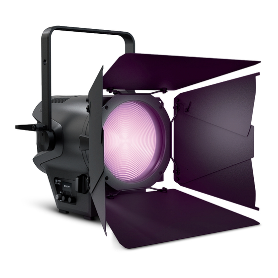
- Page 1 USER´S MANUAL BEDIENUNGSANLEITUNG MANUEL D´UTILISATION MANUAL DE USUARIO INSTRUKCJA OBSŁUGI MANUALE D´USO RGBW F2 FC POLE OPERATED PROFESSIONAL HIGH-POWER FRESNEL WITH RGBW LED CLF2FCPO...
-
Page 2: Table Of Contents
CONTENTS / INHALTSVERZEICHNIS / CONTENU / CONTENIDO / TREŚĆ / CONTENUTO ENGLISH ESPAÑOL SAFETY INFORMATION MEDIDAS DE SEGURIDAD INTRODUCTION INTRODUCCIÓN CONNECTIONS, CONTROL AND DISPLAY ELEMENTS CONEXIONES, ELEMENTOS DE MANEJO Y ELEMENTOS OPERATION DE VISUALIZACIÓN USING THE OPERATING POLE FOR SETUP, INSTALLATION, AND FUNCIONAMIENTO CONFIGURATION COLOCACIÓN, MONTAJE Y AJUSTE MEDIANTE BARRA... -
Page 3: English
We have designed this product to operate reliably over many years. Please read this User‘s Manual carefully, so that you can begin making optimum use of your Cameo Light product quickly. Learn more about Cameo Light on our website WWW.CAMEOLIGHT.COM. -
Page 4: Introduction
38. If the power cord of the device is damaged, do not use the device. The power cord must be replaced by an adequate cable or assembly from an authorized service center. CAUTION: To reduce the risk of electric shock, do not remove cover (or back). There are no user serviceable parts inside. -
Page 5: Connections, Control And Display Elements
单 位 章 客 户 备注 TRUE1-compatible output socket to supply power to additional CAMEO spotlights. Ensure that the total power consumption of all devices connected to the device does not exceed the given ampere (A) value. FUSE Fuse holder for 5 x 20 mm micro fuses. IMPORTANT NOTE: Exclusively replace the fuse with a fuse of the same type and values (T3,15A/250V). -
Page 6: Operation
NOTE • As soon as the spotlight is correctly connected to the power mains, “Welcome to Cameo”, the model designation, and then the software version are displayed in sequence on the display as part of the startup process. Once the process is complete, the spotlight is ready for use and resumes whichever mode was most recently activated. - Page 7 SETTING THE DMX MODE (DMX Mode) Starting from the main display, press on the right push button rotary encoder to move to the main menu. Rotate the left encoder (SELECT) to select the "DMX Mode" menu item (as indicated by selector arrow on left) and confirm by pressing the left encoder (ENTER). You can now select the desired DMX mode by rotating the left encoder.
- Page 8 STAND-ALONE MODE HSI (Hue - Saturation - Intensity) Starting from the main display, press on the left push button rotary encoder to move to the mode select menu. Rotate the left encoder (SELECT) to select "HSI" mode (as indicated by selector arrow on left) and confirm by pressing the left encoder (ENTER). Dim level, hue and color saturation (SAT) can now be configured using the three push button rotary encoders (see illustration).
- Page 9 STAND-ALONE MODE GEL (Color Filter Presets) Starting from the main display, press on the left push button rotary encoder to move to the mode selection menu. Rotate the left encoder (SELECT) to select "GEL" mode (as indicated by selector arrow on left) and confirm by pressing the left encoder (ENTER). The brightness level (DIM) and color filter preset (Gel) can now be set using the left and center push button rotary encoder (see illustration).
- Page 10 STAND-ALONE MODE EDIT USER color (Edit User Color) Starting from the main display, press on the right push button rotary encoder to move to the main menu. Rotate the left encoder (SELECT) to select "Edit User Color" menu item (as indicated by selector arrow on left) and confirm by pressing the left encoder (ENTER). You can now select one of the 8 color presets by rotating the left encoder and then confirm the selection by pressing on the left encoder (ENTER).
- Page 11 STAND-ALONE MODE PLAY LOOP (8-step color sequences 1 - 8) Starting from the main display, press on the left push button rotary encoder to move to the mode selection menu. Rotate the left encoder (SELECT) to select "Play Loop" mode (as indicated by selector arrow on left) and confirm by pressing the left encoder (ENTER). Now select one of the 8 preset but customizable color sequences (loops) by rotating the left encoder.
- Page 12 SLAVE MODE Starting from the main display, press on the left push button rotary encoder to move to the mode selection menu. Rotate the left encoder to select the “Slave” menu item (as indicated by selector arrow on left) and confirm by pressing the encoder (ENTER). Slave mode is now activated and the main display is automatically shown again.
- Page 13 DEVICE SETTINGS (Settings) Starting from the main display, press on the right push button rotary encoder to move to the main menu. Rotate the left encoder (SELECT) to select "Settings" menu item (as indicated by selector arrow on left) and confirm by pressing the left encoder (ENTER). This will take you to the submenu for setting the submenu options (see table, select via SELECT, confirm via ENTER, change value or status via SELECT, confirm via ENTER).
- Page 14 Autolock Automatically locks the Automatically locks the control element after approx. control element 30 seconds of inactivity. If a subsequent attempt is made to use controls, display shows: "Locked!" Unlock method: simultaneous pressing of center and right encoder for approx. 3 seconds Deactivates automatic locking of the control element Fan settings Auto...
-
Page 15: Using The Operating Pole For Setup, Installation, And Configuration
USING THE OPERATING POLE FOR SETUP, INSTALLATION, AND CONFIGURATION Thanks to its four plastic feet, the spotlight can be placed in a suitable location on a flat surface. Install on a crossbeam using the integrated 28 mm TV spigot (A) and a suitable crossbeam clamp (not supplied). Make sure that the spotlight is firmly attached and secure it using a suitable safety cable on the designated location on the top of the spotlight (B). -
Page 16: Dmx Technology
DMX TECHNOLOGY DMX-512 DMX (Digital Multiplex) is the designation for a universal transmission protocol for communications between corresponding devices and controllers. A DMX controller sends DMX data to the connected DMX device(s). The DMX data is always transmitted as a serial data stream that is forwarded from one connected device to the next via the "DMX IN"... -
Page 17: Technical Specifications
TECHNICAL SPECIFICATIONS Article number: CLF2FCPO Product type: LED Spotlight Type: Pole-Operated Fresnel Spotlight with Zoom Function Color spectrum: RGBW CRI: > 90 Number of LEDs: 1 LED array (Rx18, Gx18, Bx16, Wx37) LED type: 240 W LED PWM frequency: 600 Hz, 1200 Hz, 2000 Hz, 4000 Hz, 6000 Hz, 25 kHz (adjustable) Beam angle: 17°–53°... -
Page 18: Manufacturer's Declarations
MANUFACTURER´S DECLARATIONS MANUFACTURER‘S WARRANTY & LIMITATIONS OF LIABILITY You can find our current warranty conditions and limitations of liability at: https://cdn-shop.adamhall.com/media/pdf/MANUFACTU- RERS-DECLARATIONS_CAMEO.pdf. To request warranty service for a product, please contact Adam Hall GmbH, Adam-Hall-Str. 1, 61267 Neu Anspach / Email: Info@adamhall.com / +49 (0)6081 / 9419-0. CORRECT DISPOSAL OF THIS PRODUCT (valid in the European Union and other European countries with a differentiated waste collection system) This symbol on the product, or on its documents indicates that the device may not be treated as household waste. -
Page 19: Deutsch
Dieses Gerät wurde unter hohen Qualitätsanforderungen entwickelt und gefertigt, um viele Jahre einen reibungslosen Betrieb zu gewähr- leisten. Bitte lesen Sie diese Bedienungsanleitung sorgfältig, damit Sie Ihr neues Produkt von Cameo Light schnell und optimal einsetzen können. Weitere Informationen über Cameo Light erhalten Sie auf unserer Website WWW.CAMEOLIGHT.COM. -
Page 20: Einführung
34. Der Abstand zu brennbaren Materialien muss mindestens 0,5 m betragen. 35. Verwenden Sie zum Anschließen des Geräts an das Stromnetz ausschließlich das mitgelieferte Netzkabel. 36. Das Gerät darf nicht von Personen (einschließlich Kindern) mit eingeschränkten körperlichen, sensorischen oder geistigen Fähigkeiten oder mangelnder Erfahrung und Kenntnis benutzt werden. -
Page 21: Anschlüsse, Bedien- Und Anzeigeelemente
单 位 章 客 户 备注 TRUE1 kompatible Netzausgangsbuchse für die Netzversorgung weiterer CAMEO Scheinwerfer. Achten Sie darauf, dass die gesamte Strom- aufnahme aller angeschlossenen Geräte den auf dem Gerät in Ampere (A) angegebenen Wert nicht überschreitet. FUSE Sicherungshalter für 5 x 20mm Feinsicherungen. WICHTIGER HINWEIS: Ersetzen Sie die Sicherung ausschließlich durch eine Sicherung des gleichen Typs und mit gleichen Werten (T3,15A/250V). -
Page 22: Bedienung
• Sobald der Scheinwerfer korrekt am Stromnetz angeschlossen ist, werden während des Startvorgangs nacheinander „Welcome to Cameo“, die Modellbezeichnung und die Software Version im Display angezeigt. Nach diesem Vorgang ist der Scheinwerfer betriebsbereit und startet in der Betriebsart, die zuvor aktiviert war. - Page 23 DMX-MODUS EINSTELLEN (DMX Mode) Ausgehend von der Hauptanzeige gelangen Sie durch Drücken auf den rechten Dreh-Drück-Encoder in das Hauptmenü. Durch Drehen des linken Encoders (SELECT) wählen Sie nun den Menüpunkt „DMX Mode“ aus (Auswahlpfeil links beachten) und bestätigen durch Drücken auf den linken Encoder (ENTER).
- Page 24 STANDALONE BETRIEBSART HSI (Hue - Saturation - Intensity) Ausgehend von der Hauptanzeige gelangen Sie durch Drücken auf den linken Dreh-Drück-Encoder in das Menü zum Auswählen der Betriebsart (Mode). Durch Drehen des linken Encoders (SELECT) wählen Sie nun die Betriebsart „HSI“ aus (Auswahlpfeil links beachten) und bestätigen durch Drücken auf den linken Encoder (ENTER).
- Page 25 STANDALONE BETRIEBSART GEL (Farbfilter-Presets) Ausgehend von der Hauptanzeige gelangen Sie durch Drücken auf den linken Dreh-Drück-Encoder in das Menü zum Auswählen der Betriebsart (Mode). Durch Drehen des linken Encoders (SELECT) wählen Sie nun die Betriebsart „GEL“ aus (Auswahlpfeil links beachten) und bestätigen durch Drücken auf den linken Encoder (ENTER).
- Page 26 STANDALONE BETRIEBSART USER COLOR EDITIEREN (Edit User Color) Ausgehend von der Hauptanzeige gelangen Sie durch Drücken auf den rechten Dreh-Drück-Encoder in das Hauptmenü. Durch Drehen des linken Encoders (SELECT) wählen Sie nun den Menüpunkt "Edit User Color" aus (Auswahlpfeil links beachten) und bestätigen durch Drücken auf den linken Encoder (ENTER).
- Page 27 STANDALONE BETRIEBSART PLAY LOOP (8-Schritt-Farbsequenzen 1 - 8) Ausgehend von der Hauptanzeige gelangen Sie durch Drücken auf den linken Dreh-Drück-Encoder in das Menü zum Auswählen der Betriebsart (Mode). Durch Drehen des linken Encoders (SELECT) wählen Sie nun die Betriebsart „Play Loop“ aus (Auswahlpfeil links beachten) und bestätigen durch Drücken auf den linken Encoder (ENTER).
- Page 28 Wählen Sie Schritt 1 der 8-Schritt-Sequenz (Step1 - Step8) durch Drehen des linken Encoders aus, um danach die Farbe des Schritts festzulegen (Step1, Auswahlpfeil beachten). Nun wählen Sie eine der in der Standalone Betriebsart „User Color“ festgelegten Farben durch Drehen am mittleren Encoder aus und bestätigen die Auswahl für Schritt 1 durch Drücken auf den mittleren Encoder. Die ausgewählte Farbe des jeweiligen Schritts wird visuell durch ein hell hinterlegtes Kästchen unterhalb der Farbnummern 1 bis 8 angezeigt.
- Page 29 GERÄTEEINSTELLUNGEN (Settings) Ausgehend von der Hauptanzeige gelangen Sie durch Drücken auf den rechten Dreh-Drück-Encoder in das Hauptmenü. Durch Drehen des linken Encoders (SELECT) wählen Sie nun den Menüpunkt „Settings“ aus (Auswahlpfeil links beachten) und bestätigen durch Drücken auf den linken Encoder (ENTER). Daraufhin gelangen Sie in das Untermenü zum Einstellen der Untermenü-Punkte (siehe Tabelle, Auswahl mit SELECT, bestätigen mit ENTER, Wert bzw.
- Page 30 Autolock Automatische Sperrung Automatische Sperrung der Bedienelemente nach der Bedienelemente ca. 30 Sekunden Inaktivität. Anzeige im Display nach Bedienversuch: „Locked!“ Entsperren: Gleichzeitiges Drücken von mittlerem und rechtem Encoder für ca. 3 Sekunden Automatische Sperrung der Bedienelemente deaktiviert Lüftereinstellung Auto Automatische Lüftersteuerung Silent Deaktivierter Lüfter bei reduzierter Helligkeit Factory Reset...
-
Page 31: Aufstellung, Montage Und Einstellen Per Bedienstange
AUFSTELLUNG, MONTAGE UND EINSTELLEN PER BEDIENSTANGE Dank seiner vier Plastikfüße kann der Scheinwerfer an einer geeigneten Stelle auf eine ebene Fläche gestellt werden. Die Montage an einer Traverse erfolgt mit Hilfe des integrierten 28mm TV-Zapfens (A) und einer geeigneten TV-Traversenklemme (nicht im Lieferumfang enthalten). Sorgen Sie für feste Verbindungen und sichern Sie den Scheinwerfer mit einem geeigneten Sicherungsseil an der dafür vorgesehenen Stelle auf der Oberseite des Scheinwerfers (B). -
Page 32: Dmx Technik
DMX TECHNIK DMX-512 DMX (Digital Multiplex) ist die Bezeichnung für ein universelles Übertragungsprotokoll für die Kommunikation zwischen entsprechenden Geräten und Controllern. Ein DMX-Controller sendet DMX-Daten an das/die angeschlossene(n) DMX-Gerät(e). Die DMX-Datenübertragung erfolgt stets als serieller Datenstrom, der über die an jedem DMX-fähigen Gerät vorhandenen DMX IN- und DMX OUT-Anschlüsse (XLR-Steckverbinder) von einem angeschlossenen Gerät an das nächste weitergeleitet wird, wobei die maximale Anzahl der Geräte 32 nicht überschreiten darf. -
Page 33: Technische Daten
TECHNISCHE DATEN Artikelnummer: CLF2FCPO Produktart: LED-Scheinwerfer Typ: Stangenbedienbarer Fresnel Scheinwerfer mit Zoom-Funktion Farbspektrum: RGBW CRI: > 90 LED Anzahl: 1 LED Array (Rx18, Gx18, Bx16, Wx37) LED Typ: 240 W LED PWM Frequenz: 600 Hz, 1200 Hz, 2000 Hz, 4000 Hz, 6000 Hz, 25 kHz (einstellbar) Abstrahlwinkel: 17°... -
Page 34: Herstellererklärungen
HERSTELLERERKLÄRUNGEN HERSTELLERGARANTIE & HAFTUNGSBESCHRÄNKUNG Unsere aktuellen Garantiebedingungen und Haftungsbeschränkung finden Sie unter: https://cdn-shop.adamhall.com/media/pdf/MANUFAC- TURERS-DECLARATIONS_CAMEO.pdf. Im Service Fall wenden Sie sich bitte an Adam Hall GmbH, Adam-Hall-Str. 1, 61267 Neu Anspach / E-Mail Info@adamhall.com / +49 (0)6081 / 9419-0. KORREKTE ENTSORGUNG DIESES PRODUKTS (Gültig in der Europäischen Union und anderen europäischen Ländern mit Mülltrennung) Dieses Symbol auf dem Produkt oder dazugehörigen Dokumenten weist darauf hin, dass das Gerät am Ende der Produktlebenszeit nicht zusammen mit dem normalen Hausmüll entsorgt werden darf, um Umwelt- oder Personenschäden durch unkontrollierte Abfallentsorgung zu vermeiden. -
Page 35: Francais
Cet appareil a été développé et fabriqué en appliquant des exigences de qualité très élevées: il garantit des années de fonctionnement sans problème.Veuillez lire attentivement ce Manuel Utilisateur : vous apprendrez rapidement à utiliser votre appareil Cameo Light de façon optimale. -
Page 36: Introduction
35. Pour raccorder l’appareil au réseau électrique, utiliser uniquement le cordon d’alimentation fourni. 36. L’appareil ne peut pas être utilisé par des personnes (y compris des enfants) ayant des capacités physiques, sensorielles ou mentales limitées ou un manque d’expérience et de connaissances. 37. -
Page 37: Raccordements, Éléments De Commande Et D'affichage
单 位 章 客 户 备注 Prise de sortie secteur compatible TRUE1 pour l’alimentation d’autres projecteurs CAMEO. Assurez-vous que la consommation totale de tous les appareils connectés ne dépasse pas la valeur en ampères (A) indiquée sur l’appareil. FUSIBLE Porte-fusible pour fusibles à courant faible de 5 x 20 mm. REMARQUE IMPORTANTE : Remplacez le fusible exclusivement par un fusible de même type et comportant les mêmes valeurs (T3, 15 A/250 V). -
Page 38: Commande
REMARQUES • Dès que le projecteur est correctement raccordé à l’alimentation secteur, un message de bienvenue (« Welcome to Cameo »), la désignation du modèle et la version du logiciel s’affichent successivement à l’écran pendant la phase de démarrage. À l’issue de cette phase, le projecteur est opérationnel et passe au mode précédemment activé. - Page 39 RÉGLAGE DE L’ADRESSE DE DÉPART DMX (DMX Address) À partir de l’écran principal, appuyer sur l’encodeur rotatif à bouton poussoir de droite pour accéder au menu principal. Tourner l’encodeur de gauche (SELECT) pour sélectionner à présent l’option de menu « DMX Address » (faire attention à la flèche de sélection à gauche), puis appuyer sur l’encodeur pour valider (ENTER).
- Page 40 MODE STANDALONE CCT (Correlated Color Temperature) À partir de l’écran principal, appuyer sur l’encodeur rotatif à bouton poussoir de gauche pour accéder au menu permettant de sélectionner le mode de fonctionnement (Mode). Tourner l’encodeur de gauche (SELECT) pour sélectionner à présent le mode de fonctionnement « CCT » (faire attention à...
- Page 41 MODE STANDALONE DIRECT LED (Mélange de couleurs RGBW) À partir de l’écran principal, appuyer sur l’encodeur rotatif à bouton poussoir de gauche pour accéder au menu permettant de sélectionner le mode de fonctionnement (Mode). Tourner l’encodeur de gauche (SELECT) pour sélectionner à présent le mode de fonctionnement « Direct LED »...
- Page 42 MODE STANDALONE USER COLOR (Presets de couleur personnalisés 1 à 8) À partir de l’écran principal, appuyer sur l’encodeur rotatif à bouton poussoir de gauche pour accéder au menu permettant de sélectionner le mode de fonctionnement (Mode). Tourner l’encodeur de gauche (SELECT) pour sélectionner à présent le mode de fonctionnement « User Color »...
- Page 43 Régler ensuite la couleur voulue, comme décrit à la section du mode Standalone correspondant de ce manuel, et appuyer sur l’encodeur de gauche pour valider (ENTER/Save). MODE STANDALONE PLAY LOOP (Séquences de couleurs en 8 pas 1 à 8) À partir de l’écran principal, appuyer sur l’encodeur rotatif à bouton poussoir de gauche pour accéder au menu permettant de sélectionner le mode de fonctionnement (Mode).
- Page 44 Tourner l’encodeur de gauche pour sélectionner le pas 1 de la séquence en 8 pas (Step1 - Step8) afin de définir ensuite la couleur du pas (Step1, faire attention à la flèche de sélection). Tourner à présent l’encodeur du milieu pour sélectionner l’une des couleurs définies du mode Standalone « User Color », puis confirmer la sélection pour le pas 1 en appuyant sur l’encodeur du milieu.
- Page 45 PARAMÈTRES DE L’APPAREIL (Settings) À partir de l’écran principal, appuyer sur l’encodeur rotatif à bouton poussoir de droite pour accéder au menu principal. Tourner l’encodeur de gauche (SELECT) pour sélectionner à présent l’option de menu « Settings » (faire attention à la flèche de sélection à gauche), puis appuyer sur l’encodeur de gauche pour valider (ENTER).
- Page 46 Color Calibration Étalonnage des R, G, B et W d’une valeur maximale de 255 couleurs User Calibration Appuyer sur l’encodeur du milieu = Basculer entre (Ajustement individuel R+G et B+W (Color) des couleurs R, G, B Tourner l’encodeur du milieu = Régler la valeur des et W avec des valeurs couleurs R ou B allant chacune de 000...
-
Page 47: Installation, Montage Et Ajustement Par Barre De Réglage
Fréquence du signal PWM de la LED Calibr. Étalonnage d’usine / Pas d’ajustement / Ajustement défini par l’utilisateur Color-Cal. R Ajustement du rouge (concerne tous les modes de fonctionnement) Color-Cal. G Ajustement du vert (concerne tous les modes de fonctionnement) Color-Cal. -
Page 48: Montage/Démontage Du Volet Coupe-Flux Et Du Cadre Pour Filtre / Nettoyage Des Lentilles
MONTAGE/DÉMONTAGE DU VOLET COUPE-FLUX ET DU CADRE POUR FILTRE / NETTOYAGE DES LENTILLES Débrancher complètement l’appareil du réseau électrique. Pour monter ou démonter le volet coupe-flux et le cadre pour filtre, appuyer sur le boulon de verrouillage à ressort (D) du dispositif de maintien de sorte que celui-ci se rabatte vers le haut. Replacer ensuite le dispositif de maintien dans sa position d’origine, de sorte que le boulon de verrouillage s’enclenche à... -
Page 49: Caractéristiques Techniques
Assignation des contacts Câble DMX avec connecteurs XLR 3 points : Câble DMX avec connecteurs XLR 5 points (les points 4 et 5 ne sont pas câblés): Shield Shield Pour éviter tout dysfonctionnement, le dernier appareil d'une chaîne DMX doit être équipé d'une résistance de terminaison (120 Ohms, 1/4 Watt). -
Page 50: Déclarations Du Fabricant
Pilotage : DMX512, compatible RDM Éléments de commande : 3 encodeurs rotatifs à bouton poussoir, zoom manuel, cloches de contrôle par barre de réglage pour les fonctions zoom, Pan et Tilt Éléments d‘affichage : Écran OLED Tension de fonctionnement : 100 - 240 V CA / 50 - 60 Hz Puissance absorbée : 220 W Flux lumineux :... -
Page 51: Español
Este equipo está diseñado y fabricado con los estándares de calidad más exigentes, para garantizar un correcto funcionamiento durante muchos años.Lea atentamente este manual de usuario para poder aprovechar rápidamente toda la funcionalidad de su nuevo producto de Cameo Light. Más información sobre Cameo Light en la web WWW.CAMEOLIGHT.COM. MEDIDAS DE SEGURIDAD 1. -
Page 52: Introducción
34. Asimismo, deberá dejarse una distancia mínima de 0,5 metros con cualquier material inflamable. 35. Para conectar el equipo a la red eléctrica, utilice solamente el cable de alimentación suministrado. 36. El equipo no debe ser utilizado por personas (incluidos niños) con capacidades físicas, sensoriales o mentales reducidas o sin la expe- riencia y los conocimientos necesarios. -
Page 53: Conexiones, Elementos De Manejo Y Elementos De Visualización
备注 Toma de salida de alimentación compatible con TRUE1 para la alimentación eléctrica de otros focos CAMEO. Asegúrese de que el consumo de corriente total de todos los equipos conectados no supere el valor en amperios (A) indicado en el equipo. -
Page 54: Funcionamiento
• En cuanto el foco esté correctamente conectado a la red eléctrica, durante el proceso de arranque se mostrarán de forma consecutiva en pantalla el mensaje «Welcome to Cameo» (Bienvenidos a Cameo), así como la denominación del modelo y la versión del software. Tras este procedimiento, el foco estará... - Page 55 CONFIGURACIÓN DE LA DIRECCIÓN INICIAL DMX (dirección DMX) Partiendo de la pantalla principal, si pulsa el mando giratorio derecho, accederá al menú principal. Girando el mando giratorio izquierdo (SELECT), seleccione ahora la opción de menú «DMX Address» (observe la flecha de selección en el lado izquierdo) y confirme su selección pulsando dicho mando (ENTER).
- Page 56 MODO OPERATIVO AUTÓNOMO CCT (Correlated Color Temperature) Partiendo de la pantalla principal, si pulsa el mando giratorio izquierdo, accederá al menú para seleccionar el modo operativo (Mode). Girando el mando giratorio izquierdo (SELECT), seleccione ahora el modo operativo «CCT» (observe la flecha de selección en el lado izquierdo) y confirme su selección pulsando dicho mando (ENTER).
- Page 57 MODO OPERATIVO AUTÓNOMO DIRECT LED (Mezcla de colores RGBW) Partiendo de la pantalla principal, si pulsa el mando giratorio izquierdo, accederá al menú para seleccionar el modo operativo (Mode). Girando el mando giratorio izquierdo (SELECT), seleccione ahora el modo operativo «Direct LED» (observe la flecha de selección en el lado izquierdo) y confirme su selección pulsando ese mismo mando (ENTER).
- Page 58 MODO OPERATIVO AUTÓNOMO USER COLOR (preajustes de color individuales 1 - 8) Partiendo de la pantalla principal, si pulsa el mando giratorio izquierdo, accederá al menú para seleccionar el modo operativo (Mode). Girando el mando giratorio izquierdo (SELECT), seleccione ahora el modo operativo «User Color» (observe la flecha de selección en el lado izquierdo) y confirme su selección pulsando ese mismo mando (ENTER).
- Page 59 A continuación, configure el color deseado, tal como se describe en el manual de cada modo operativo autónomo, y para confirmar pulse el mando giratorio izquierdo (ENTER/Save). MODO OPERATIVO AUTÓNOMO PLAY LOOP (secuencias de color en 8 pasos 1 - 8) Partiendo de la pantalla principal, si pulsa el mando giratorio izquierdo, accederá...
- Page 60 Seleccione el paso 1 de la secuencia de 8 pasos (Step1 - Step8) girando el mando giratorio izquierdo para, acto seguido, determinar el color del paso (Step1, observe la flecha de selección). Ahora, seleccione uno de los colores configurados en el modo operativo autónomo «User Color»...
- Page 61 CONFIGURACIÓN DEL DISPOSITIVO (Settings) Partiendo de la pantalla principal, si pulsa el mando giratorio derecho, accederá al menú principal. Girando el mando giratorio izquierdo (SE- LECT), seleccione ahora la opción de menú «Settings» (observe la flecha de selección en el lado izquierdo) y confirme su selección pulsando dicho mando (ENTER).
- Page 62 Color Calibration Calibración del color R, G, B y W con valor máximo 255 User Calibration Pulsar mando giratorio medio = conmutación entre (ajuste individual R+G y B+W (Color) para todos los modos Girar mando giratorio medio = configurar el valor de operativos de R, G, B y R o B W, cada uno con valores...
-
Page 63: Colocación, Montaje Y Ajuste Mediante Barra
System Info Main CPU Firmware del dispositivo LED Temp. Visualización de la temperatura del LED en grados centígrados y Fahrenheit Op. Hours Tiempo total de funcionamiento en horas y minutos Display Apagado de la pantalla activado/desactivado DMX Fail Estado operativo en caso de interrupción de la señal DMX Dim Curve Curva de atenuación Dim Response... -
Page 64: Montar/Desmontar La Visera Y El Bastidor De Filtro / Limpiar Las Lentes
MONTAR/DESMONTAR LA VISERA Y EL BASTIDOR DE FILTRO / LIMPIAR LAS LENTES Desconecte el equipo completamente de la red eléctrica. Para montar o desmontar la visera y el portafiltros, presione el perno de bloqueo con resorte (A) del dispositivo de sujeción de modo que se abra hacia arriba. Después, devuelva el dispositivo de sujeción a su posición original, de forma que el perno de bloqueo vuelva a encajar en su sitio. -
Page 65: Datos Técnicos
Asignación de pines: Cable DMX con XLR de 3 pines: Cable DMX con XLR de 5 pines (los pines 4 y 5 no se utilizan): Shield Shield TERMINACIÓN DMX (TERMINADOR): Para evitar errores de sistema, debe conectarse una resistencia de terminación (120 ohmios, 1/4 W) en el último equipo de la cadena DMX. XLR aéreo de 3 pines con resistencia de terminación: K3DMXT3 XLR aéreo de 5 pines con resistencia de terminación: K3DMXT5 Asignación de pines:... -
Page 66: Declaraciones Del Fabricante
Configuración del sistema: Giro de pantalla, iluminación de pantalla on/off, DMX Fail, curvas de atenuación, respuesta de atenuación, Red Shift, frecuencia de modulación por ancho de pulsos (PWM), calibración del color, Auto Lock, ajuste del ventilador, restablecimiento de la configuración de fábrica, UC/ Loops Reset Control: DMX512, habilitado para RDM... -
Page 67: Polski
To urządzenie zostało zaprojektowane i wyprodukowane przy zastosowaniu najwyższych kryteriów jakościowych w celu zapewnienia wieloletniej bezawaryjnej eksploatacji. Proszę starannie przeczytać niniejszą instrukcję obsługi, aby móc jak najszybciej zacząć użytkować ten produkt marki Cameo Light. Więcej informacji na temat Cameo Light znajdą Państwo na naszej stronie internetowej pod adresem WWW.CAMEOLIGHT.COM. -
Page 68: Wprowadzenie
32. Instalacja urządzenia powinna odbywać się, gdy urządzenie nie jest podłączone do źródła zasilania (należy wyjąć wtyczkę z gniazda). 33. Kurz i inne osady wewnątrz urządzenia mogą je uszkodzić. W zależności od warunków otoczenia (kurz, nikotyna, opary itp.) urządzenie powinno być konserwowane lub czyszczone przez wykwalifikowanego specjalistę (usługa nieobjęta gwarancją), aby zapobiec przegrzaniu i nieprawidłowemu działaniu. -
Page 69: Gniazda, Elementy Obsługi I Wskaźniki
单 位 章 客 户 备注 Sieciowe gniazdo wyjściowe TRUE1 do zasilania sieciowego innych reflektorów CAMEO. Należy się upewnić, że całkowity pobór prądu wszystkich podłączonych urządzeń nie przekracza wartości w amperach (A) podanej na urządzeniu. FUSE Podstawa na czułe bezpieczniki 5 x 20 mm. WAŻNA WSKAZÓWKA: bezpiecznik można wymieniać wyłącznie na bezpiecznik tego samego typu i o takich samych parametrach (T3, 15 A/250 V). -
Page 70: Obsługa
WSKAZÓWKI • Po prawidłowym podłączeniu reflektora do sieci zasilania podczas procesu uruchamiania wyświetlana jest następująca sekwencja komunikatów: „Welcome to Cameo”, nazwa modelu oraz wersja oprogramowania. Następnie reflektor jest gotowy do pracy i przełącza się na ostatnio wybrany tryb. • Jeśli aktywowano jeden z trybów DMX lub tryb slave, a na wejściu DMX nie ma sygnału, znaki na wyświetlaczu zaczynają migać. - Page 71 USTAWIANIE ADRESU STARTOWEGO DMX (DMX Address) Jeśli wyświetlany jest ekran główny i naciśnięty zostanie prawy enkoder obrotowo-przyciskowy, nastąpi przejście do menu głównego. Poprzez obrócenie lewego enkodera (SELECT) wybrać punkt menu „DMX Address” (zwrócić uwagę na strzałkę wyboru z lewej strony). Aby potwierdzić, nacisnąć ten enkoder (ENTER). Teraz można ustawić adres startowy DMX według życzeń poprzez obrócenie lewego enkodera (najwyższa wartość...
- Page 72 TRYB PRACY STANDALONE CCT (Correlated Color Temperature) Jeśli wyświetlany jest ekran główny i naciśnięty zostanie lewy enkoder obrotowo-przyciskowy, nastąpi przejście do menu pozwalającego na wybór trybu pracy (Mode). Poprzez obrócenie lewego enkodera (SELECT) wybrać tryb pracy „CCT” (zwrócić uwagę na strzałkę wyboru z lewej strony).
- Page 73 TRYB PRACY STANDALONE DIRECT LED (mieszanie kolorów RGBW) Jeśli wyświetlany jest ekran główny i naciśnięty zostanie lewy enkoder obrotowo-przyciskowy, nastąpi przejście do menu pozwalającego na wybór trybu pracy (Mode). Poprzez obrócenie lewego enkodera (SELECT) wybrać tryb pracy „Direct LED” (zwrócić uwagę na strzałkę wyboru z lewej strony).
- Page 74 TRYB PRACY STANDALONE USER COLOR (indywidualne ustawienia wstępne kolorów 1–8) Jeśli wyświetlany jest ekran główny i naciśnięty zostanie lewy enkoder obrotowo-przyciskowy, nastąpi przejście do menu pozwalającego na wybór trybu pracy (Mode). Poprzez obrócenie lewego enkodera (SELECT) wybrać tryb pracy „User Color” (zwrócić uwagę na strzałkę wyboru z lewej strony).
- Page 75 Następnie ustawić żądany kolor w sposób opisany w instrukcji danego trybu standalone i potwierdzić ustawienie, naciskając lewy enkoder (ENTER/Save). TRYB PRACY STANDALONE PLAY LOOP (8-krokowa sekwencja kolorów 1–8) Jeśli wyświetlany jest ekran główny i naciśnięty zostanie lewy enkoder obrotowo-przyciskowy, nastąpi przejście do menu pozwalającego na wybór trybu pracy (Mode).
- Page 76 Wybrać krok 1 sekwencji 8-krokowej (Step1–Step8), obracając lewy enkoder, aby następnie ustawić kolor kroku (Step1, zwrócić uwagę na strzałkę wyboru). Teraz wybrać jeden z kolorów ustawionych w trybie pracy standalone „User Color” poprzez obrócenie środkowego enkodera i potwierdzić wybór dla kroku 1 poprzez naciśnięcie środkowego enkodera. Wybrany kolor danego kroku zostanie oznaczony jasno podświetlonym polem pod numerem koloru od 1 do 8.
- Page 77 USTAWIENIA URZĄDZENIA (Settings) Jeśli wyświetlany jest ekran główny i naciśnięty zostanie prawy enkoder obrotowo-przyciskowy, nastąpi przejście do menu głównego. Poprzez obrócenie lewego enkodera (SELECT) wybrać punkt menu „Settings” (zwrócić uwagę na strzałkę wyboru z lewej strony). Aby potwierdzić, nacisnąć lewy enkoder (ENTER). Nastąpi przejście do podmenu, w którym można dokonać ustawień punktów podmenu (patrz tabela, wybór przyciskiem SELECT, potwierdzenie przyciskiem ENTER, zmiana wartości lub statusu przyciskiem SELECT, potwierdzenie przyciskiem ENTER).
- Page 78 Autolock automatyczna blokada Automatyczna blokada elementów obsługi po ok. 30 elementów obsługi sekundach bezczynności. W razie próby obsługi na wyświetlaczu pojawi się komunikat: „Locked!” Aby odblokować: jednocześnie nacisnąć środkowy i prawy enkoder i przytrzymać przez ok. 3 sekundy Automatyczna blokada elementów obsługi jest wyłączona ustawienie wentylatora Auto...
-
Page 79: Instalacja, Montaż I Regulacja Za Pomocą Drążka Operacyjnego
RĘCZNA FUNKCJA BLOKOWANIA Oprócz automatycznego zabezpieczenia reflektora przed omyłkowym wprowadzeniem zmian lub nieuprawnionym dostępem (patrz „Settings” – „Autolock”) możliwe jest także ręczne zablokowanie elementów obsługi. Jednocześnie nacisnąć środkowy i prawy enkoder obrotowo-przyciskowy i przytrzymać przez około 3 sekundy. Teraz przy próbie zmiany ustawień na wyświetlaczu pojawi się komunikat „Locked!”... -
Page 80: Montaż Wrót Reflektora I Ramki Filtra / Demontaż / Czyszczenie Soczewek
MONTAŻ WRÓT REFLEKTORA I RAMKI FILTRA / DEMONTAŻ / CZYSZCZENIE SOCZEWEK Odłączyć wszystkie bieguny urządzenia od sieci elektrycznej. W celu montażu lub demontażu osłony reflektora i ramki filtra należy wcisnąć sprężynowy trzpień blokujący (E) uchwytu przytrzymującego, tak aby złożył się do góry. Następnie przestawić uchwyt przytrzymujący z powrotem do pierwotnego położenia, tak aby trzpień... -
Page 81: Dane Techniczne
Przyporządkowanie wtyczek: Kabel DMX z 3-stykowymi wtyczkami XLR: Kabel DMX z 5-stykowymi wtyczkami XLR (pin 4 i 5 są niepodłączone): Shield Shield TERMINATOR DMX: Aby zapobiec awariom systemu, należy wyposażyć ostatnie urządzenie w łańcuchu DMX w terminator (120 Ω, 1/4 W). 3-stykowa wtyczka XLR z terminatorem: K3DMXT3 5-stykowa wtyczka XLR z terminatorem: K3DMXT5 Przyporządkowanie wtyczek:... -
Page 82: Oświadczenia Producenta
Wskaźniki: WYŚWIETLACZ OLED Napięcie robocze: 100 V-240 V AC, 50-60 Hz Pobór mocy: 220 W Strumień świetlny: 6500 lm Wydajność: 27 lm/W Złącze zasilacza sieciowego: INPUT: TRUE1 kompatybilny OUTPUT: TRUE1 kompatybilny (maks. 6 A) Bezpiecznik: T3, 15 A / 250 V (5 x 20 mm) Temperatura otoczenia (w czasie pracy): Od -10°C do 45°C Wilgotność... -
Page 83: Italiano
Questo dispositivo è stato sviluppato e prodotto in conformità con elevati standard qualitativi che ne garantiscono il regolare funzionamento per molti anni. Leggete attentamente questo manuale d‘uso per utilizzare al meglio il vostro nuovo prodotto Cameo Light. Per maggiori informazioni su Cameo Light consultare la nostra pagina Web WWW.CAMEOLIGHT.COM. -
Page 84: Introduzione
36. Il dispositivo non deve essere utilizzato da persone (compresi i bambini) con capacità fisiche, sensoriali o mentali limitate o con scarsa esperienza e conoscenza. 37. I bambini devono essere istruiti a non giocare con il dispositivo. 38. Se il cavo di alimentazione del dispositivo è danneggiato, quest‘ultimo non deve essere utilizzato. Il cavo di alimentazione deve essere sostituito con un cavo appropriato o un‘unità... -
Page 85: Collegamenti, Elementi Di Comando E Di Indicazione
单 位 章 客 户 备注 Presa di uscita compatibile con TRUE1 per l’alimentazione elettrica di altri proiettori CAMEO. Tener presente che la corrente assorbita da dispositivi collegati non deve superare il valore in ampere (A) indicato. FUSE Portafusibili per microfusibili 5 x 20 mm. NOTA IMPORTANTE: Sostituire il fusibile solo con un altro dello stesso tipo e con gli stessi valori (T3,15A/250V). -
Page 86: Utilizzo
• Non appena il proiettore è correttamente allacciato alla rete elettrica, durante il processo di avvio sul display appaiono in successione il messaggio “Welcome to Cameo”, la denominazione del modello e la versione del software. Dopo questo processo il proiettore sarà pronto per l’uso e si avvierà... - Page 87 IMPOSTAZIONE DELLA MODALITÀ DMX (DMX Mode) Premere il codificatore girevole a pulsante a destra per accedere al menu principale dalla schermata principale. Ruotare il codificatore sinistro (SELECT) per selezionare la voce di menu “DMX Mode” (osservare la freccia di selezione a sinistra) e confermare premendo il codificatore sinistro (ENTER).
- Page 88 MODALITÀ DI FUNZIONAMENTO STAND-ALONE HSI (Hue - Saturation - Intensity) Premere il codificatore girevole a pulsante a sinistra nel menu per selezionare la modalità di funzionamento (Mode) nella schermata princi- pale. Ruotare il codificatore sinistro (SELECT) per selezionare la modalità di funzionamento “HSI” (osservare la freccia di selezione a sinistra) e confermare premendo il codificatore sinistro (ENTER).
- Page 89 MODALITÀ DI FUNZIONAMENTO STAND-ALONE GEL (preimpostazioni filtro cromatico) Premere il codificatore girevole a pulsante a sinistra nel menu per selezionare la modalità di funzionamento (Mode) nella schermata principale. Ruotare il codificatore sinistro (SELECT) per selezionare la modalità di funzionamento “GEL” (osservare la freccia di selezione a sinistra) e confermare premendo il codificatore sinistro (ENTER).
- Page 90 MODALITÀ DI FUNZIONAMENTO STAND-ALONE MODIFICA USER COLOR (Edit User Color) Premere il codificatore girevole a pulsante a destra per accedere al menu principale dalla schermata principale. Ruotare il codificatore sinistro (SELECT) per selezionare la voce di menu “Edit User Color” (osservare la freccia di selezione a sinistra) e confermare premendo il codificatore sinistro (ENTER).
- Page 91 MODALITÀ DI FUNZIONAMENTO STAND-ALONE PLAY LOOP (sequenze cromatiche in 8 passi 1 - 8) Premere il codificatore girevole a pulsante a sinistra nel menu per selezionare la modalità di funzionamento (Mode) nella schermata principale. Ruotare il codificatore sinistro (SELECT) per selezionare la modalità di funzionamento “Play Loop” (osservare la freccia di selezione a sinistra) e confermare premendo il codificatore sinistro (ENTER).
- Page 92 Selezionare il passo 1 della sequenza in 8 passi (Step1 - Step8) ruotando il codificatore sinistro per definire il colore di quel passo (Step1, prestare attenzione alla freccia di selezione). Adesso selezionare uno dei colori “User Color” definiti nella modalità di funzionamento stand-alone ruotando il codificatore centrale e confermando la selezione del passo 1 premendo lo stesso codificatore.
- Page 93 IMPOSTAZIONI DEL DISPOSITIVO (Settings) Premere il codificatore girevole a pulsante a destra per accedere al menu principale dalla schermata principale. Ruotare il codificatore sinistro (SELECT) per selezionare la voce di menu “Settings” (osservare la freccia di selezione a sinistra) e confermare premendo lo stesso codificatore (ENTER).
- Page 94 Color Calibration calibrazione dei colori R, G, B e W con valore massimo di 255 User Calibration Pressione sul codificatore centrale = commutazione (Adattamento persona- tra R+G e B+W (Color) lizzato per più modalità Rotazione del codificatore centrale = impostazione del di funzionamento R, G, valore di R o B B e W con valori com-...
-
Page 95: Installazione, Montaggio E Impostazione Tramite Asta Di Comando
frequenza LED PWM Calibr. Calibrazione di fabbrica / nessun adattamento / adattamento definito dall’utente Color-Cal. R Adattamento del rosso per tutte le modalità di funzionamento Color-Cal. G Adattamento del verde per tutte le modalità di funzionamento Color-Cal. B Adattamento del blu per tutte le modalità di funzionamento Color-Cal. -
Page 96: Montaggio E Smontaggio Del Paraluce E Del Portafiltro / Pulizia Delle Lenti
MONTAGGIO E SMONTAGGIO DEL PARALUCE E DEL PORTAFILTRO / PULIZIA DELLE LENTI Staccare tutti i poli del dispositivo dalla rete elettrica. Per montare o smontare il paraluce e il portafiltro, premere il perno di bloccaggio a molla (A) del dispositivo di blocco in modo che si ripieghi verso l’alto. Riportare poi il dispositivo di blocco nella posizione di partenza, in modo tale da far scattare nuovamente il perno di bloccaggio. -
Page 97: Dati Tecnici
Configurazione dei connettori: Cavo DMX con connettori XLR a 3 poli: Cavo DMX con connettori XLR a 5 poli (pin 4 e 5 non assegnati): Shield Shield CONNETTORE TERMINALE DMX (TERMINATORE): Per evitare errori di sistema, l'ultimo dispositivo di una catena DMX deve essere dotato di una resistenza di terminazione (120 ohm, 1/4 W). Connettore XLR a 3 poli con resistenza di terminazione: K3DMXT3 Connettore XLR a 5 poli con resistenza di terminazione: K3DMXT5 Configurazione dei connettori:... -
Page 98: Dichiarazioni Del Produttore
Elementi di visualizzazione: Display OLED Tensione di esercizio: 100 - 240 V AC / 50 - 60 Hz Potenza assorbita: 220 W Flusso luminoso: 6500 lm Efficienza: 27 lm/W Collegamento alimentazione elettrica: INPUT: compatibile con TRUE1 OUTPUT: compatibile con TRUE1 (max 6 A) Fusibile: T3,15A / 250 V (5 x 20 mm) Temperatura ambiente... -
Page 99: Dmx Control
DMX CONTROL / DMX STEUERUNG / PILOTAGE DMX / CONTROL DMX / STEROWANIE DMX / CONTROLLO DMX 1 CH DIM Mode (User Color 1) Function Values Sub-Group Dimmer 0% to 100% Dimmer 6 CH HSI-CCT Mode (16Bit) Function Values Sub-Group Dimmer 0% to 100% Dimmer fine... - Page 100 4 CH Direct Mode (RAW) Function Values Sub-Group 0% to 100% Green 0% to 100% Green Blue 0% to 100% Blue White 0% to 100% White 8 CH Direct 16Bit Mode (RAW) Function Values Sub-Group 0% to 100% Red fine 0% to 100% Green 0% to 100%...
- Page 101 Roscolux Filter Lee Filter No. no function 46 Dark Magenta 29 Plasa Red 26 Bright Red 127 Smokey Pink 36 Medium Pink 19 Fire 135 Deep Golden Amber Color Macro (override HSI 778 Millennium Gold + CCT) 21 Gold Amber 157 Pink 110 Middle Rose 109 Light Salmon...
- Page 102 105 Orange 20 Medium Amber 768 Egg Yolk Yellow 15 Deep Straw 767 Oklahoma Yellow 101 Yellow 100 Spring Yellow 88 Lime Green 121 LEE Green 738 Jas Green 4460 89 Moss Green 139 Primary Green 124 Dark Green 323 Jade 354 Special Steel Blue 116 Medium Blue-Green 183 Moonlight Blue...
- Page 103 no function Dimmer Response LED (Hold 1,5s) Dimmer Response Halogen (Hold 1,5s) DTW (Redshift) on (Hold 1,5s) DTW (Redshift) off (Hold 1,5s) no function Silent Fan (Hold 3s) Auto Fan (Hold 3s) no function LED Frequency 600Hz (hold 3s) LED Frequency 1200Hz (hold 3s) LED Frequency 2000Hz (hold 3s) Device LED Frequency 4000Hz (hold 3s)
- Page 104 Bulb White (2700K) Halogen White (3200K) Neutral White (4000K) Studio-White (5600K) Daylight White (6500K) 1600K - 6500K no function Magenta -> neutral Tint neutral neutral -> Green Roscolux Filter Lee Filter No. no function 46 Dark Magenta 29 Plasa Red 26 Bright Red 127 Smokey Pink (override...
- Page 105 110 Middle Rose 109 Light Salmon 35 Light Pink 134 Golden Amber 17 Surprise Peach 746 Brown 105 Orange 20 Medium Amber 768 Egg Yolk Yellow 15 Deep Straw 767 Oklahoma yellow 101 Yellow 100 Spring Yellow 88 Lime Green 121 LEE Green 738 Jas Green 4460...
- Page 106 0,1s - 10s (0,1s Steps) Transition Time Color Macro 11s - 119s (1s Steps) between Color Crossfade Macros 2m - 4m50s (10s Steps) 5m - 15m (1m Steps) no function Dimmer Response LED (Hold 1,5s) Dimmer Response Halogen (Hold 1,5s) DTW (Redshift) on (Hold 1,5s) DTW (Redshift) off (Hold 1,5s) no function...
- Page 108 CAMEOLIGHT.COM Adam Hall GmbH | Adam-Hall-Str. 1 | 61267 Neu-Anspach | Germany Phone: +49 6081 9419-0 | adamhall.com REV: 03...
Need help?
Do you have a question about the F Series and is the answer not in the manual?
Questions and answers