
Related Manuals for Steris AMSCO 5000 Series


Summary of Contents for Steris AMSCO 5000 Series
- Page 1 AMSCO® 5000 Series Washer/Disinfector Model #5052 Operator Manual 10057344 Revision H...
- Page 3 Any alteration of this equipment not authorized or performed by STERIS will void the warranty. Alteration of equipment which could adversely affect its operation and efficacy may violate national, state and local regulations.
- Page 4 STERIS maintains a global staff of well-equipped, qualified service technicians to provide this service, as well as expert repair services. Please contact STERIS for details. STERIS provides a line of accessories for use with this washer/disinfector. A STERIS representative will gladly review these with you.
- Page 5 — A Word from STERIS • Decontamination of reusable medical devices: ◻ CAN/CSA Z314.8-2008. This AMSCO 5052 Single-Chamber Washer/Disinfector meets the following EMC/EMI regulations: • Code of Federal Regulation, CFR 47 (2012) – FCC PART 15, SUBPART B Class A – Unintentional Radiators for Use in Commercial and Industrial Areas.
- Page 6 +33 5 56 93 94 94 European Community Representative: STERIS Ireland Limited IDA Business and Technology Park Tullamore County Offaly R35 X865 Ireland Website: www.steris.com Printed in Canada. © 2022, STERIS Corporation. All rights reserved. 10057344_H Operator Manual AMSCO® 5000 Series...
-
Page 7: Table Of Contents
TABLE OF CONTENTS Section Number Description Page Safety Precautions ............................1 Safety Precautions — Introduction ..................1 Safety Precautions ........................1 Symbols and Labels............................5 Equipment Symbols........................5 Nameplate Symbols ........................6 Transportation and Storage....................... 6 Component Identification ..........................8 Component Identification —... - Page 8 5.15 Test Menu ..........................84 5.16 Cycle History Menu........................86 5.17 Formatting USB Key ......................... 88 Routine Maintenance ..........................95 Routine Maintenance — Introduction ..................95 Preventive Maintenance ......................95 Routine Maintenance ....................... 96 Cleaning Debris Screen......................98 Cleaning Water Outlet Connection ..................99 Cleaning Door Gasket ......................100 Cleaning Washer/Disinfector Exterior...................100 Inspecting and Cleaning Rotary Spray Arm Assemblies ............102...
- Page 9 7.31 Alarm# 29 Unload Door Obstruction..................130 7.32 Alarm# 30 Water Level Defective ..................131 7.33 Alarm# 31 Low Pressure Detected ..................132 7.34 Alarm# 32 Drying System Not Heating ................133 7.35 Alarm# 33 Unload Conveyor Full...................134 7.36 Alarm# 41 to 45 Chemical Container [X] Empty ..............134 7.37 Abnormal noise generated by washer/disinfector...............135 7.38...
-
Page 10: Safety Precautions
1 — Safety Precautions Safety Precautions 1.1 Safety Precautions — Introduction The following Safety Precautions must be observed when uncrating/installing, operating or servicing this equipment. WARNING indicates the potential for personal injury and CAUTION indicates the potential for damage to equipment. It is important to review ALL Safety Precautions before operating or servicing the equipment. - Page 11 Maintenance Manual if preventive maintenance is done by the Customer. Repairs and adjustments to this equipment must be made only by STERIS or STERIS- trained service personnel. Repairs and adjustments performed by unqualified personnel or installation of unauthorized parts could cause personal injury, result in improper equipment performance, void the warranty or result in costly damage.
- Page 12 Placing washer/disinfector Power (ON/OFF) toggle switch in OFF position to turn off washer/disinfector DOES NOT cut off electrical power. Repairs and adjustments to this equipment must be made only by STERIS or STERIS- trained service personnel. Service personnel must disconnect all utilities to unit before servicing.
- Page 13 1 — Safety Precautions CAUTION POSSIBLE EQUIPMENT DAMAGE Always position manifold rack over the manifold connector before operating washer/disinfector. If manifold rack and/or bottom rotary spray arm assembly are not positioned correctly, damage may result and washer/disinfector will be unable to effectively wash load.
-
Page 14: Symbols And Labels
2 — Symbols and Labels Symbols and Labels 2.1 Equipment Symbols The table below contains symbols which may be on your washer/disinfector components: Table 2-1. Definition of Symbols on Washer/Disinfector Symbol Definition Protective Earth (Ground). Warning! Risk of Electrical Shock. Attention. -
Page 15: Nameplate Symbols
2 — Symbols and Labels 2.2 Nameplate Symbols The table below contains symbols which may be on the identification nameplate of your equipment: Table 2-2. Definition of Symbols Symbol Definition Model of Equipment. Serial Number of Equipment. Unique Device Identification. Year of Manufacture of the Equipment. - Page 16 2 — Symbols and Labels Table 2-3. Definition of Symbols on Crates Symbol Definition Maximum Shipping and Storing Temperature. Maximum Humidity Level. This Way Up. Do not Stack. Fragile. Keep Dry. 10057344_H Operator Manual AMSCO® 5000 Series...
-
Page 17: Component Identification
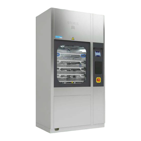
3 — Component Identification Component Identification 3.1 Component Identification — Introduction IMPORTANT: A listing of the Safety Precautions to be observed when operating and servicing this equipment can be found in Safety Precautions section of this manual. Do not operate the equipment until you have become familiar with this information. 3.2 Washer/Disinfector —... - Page 18 3 — Component Identification Load Side Shown Chamber Door USB Port Control System Printer (Accessory) Emergency Stop Pushbutton 10057344_H Operator Manual AMSCO® 5000 Series...
- Page 19 3 — Component Identification Load Side Shown Chamber Door Control System Power (ON/OFF) Toggle Switch Printer (Accessory) USB Port Emergency Stop Pushbutton Chamber The high-quality stainless-steel chamber is equipped with a debris screen, to prevent large debris from entering the piping system and pump, and with two rotary spray arm assemblies.
- Page 20 3 — Component Identification Rotary Spray Arm Assemblies Washer/disinfector includes two rotary spray arm assemblies (one at the top and one at the bottom of the chamber) to help in reaching all surfaces of the processed load. Rotary spray arm assemblies are easily accessed for maintenance purposes. Light Top Rotary Spray Arm Assembly Bottom Rotary Spray Arm Assembly...
- Page 21 3 — Component Identification Facing Non-Service Side Condenser A condenser is available for use with a non-vented washer/ disinfector. Condenser is located behind the upper access panel, on left side when facing service side of washer/disinfector. A condenser is necessary if the washer/disinfector cannot be connected to a building vent system exhausting air outside the building.
-
Page 22: Control System
3 — Component Identification The chemical dosing system allows the use of the Prolystica Ultra Concentrate chemicals (refer to Section 3.7, ® Chemicals and Cycles for more details). Each ultra concentrated product is ten times the concentration of a traditional product, therefore ten times less chemical is injected to properly process the cycles. - Page 23 3 — Component Identification Passwords A password is used to access the Supervisor mode. A predefined password is used to access the Service mode. Only a qualified service technician can access the Service mode. A password is used to open door and access load when a cycle is aborted prior to completion of disinfection. This password is known as the load access code (1379).
- Page 24 3 — Component Identification Table 3-1. Touch Pads Supervisor mode: Press Supervisor mode on Ready screen to access Supervisor mode. Service mode: Press Service mode on Ready screen to access Service mode. Save: Press Save on touch screen to save a selection or a modification and return to previous screen.
- Page 25 3 — Component Identification Table 3-1. Touch Pads (continued) Decontamination: Press Decontamination on touch screen to select the preprogrammed Decontamination cycle. Abort: Press Abort on touch screen. Cycle can be aborted (Yes) or resumed (No). Silence Buzzer: Press Silence Buzzer on touch screen to stop alarm buzzer.
-
Page 26: Emergency Safety Features
3 — Component Identification Power (ON/OFF) Toggle Switch Press top portion of Power (ON/OFF) toggle switch (located on service side of washer/disinfector) to turn power ON. Press bottom portion to turn power OFF. Pressing bottom portion of Power (ON/OFF) toggle switch turns off control system only. IMPORTANT: Power (ON/OFF) toggle switch should remain in ON position at all times, except for maintenance purposes. -
Page 27: Scs Conveyor System
3 — Component Identification Door Interlock A door interlock feature allows only one door to be opened at a time to avoid cross-contamination. Load Access Code A safety feature prevents opening of doors if a cycle has not been successfully completed. When a cycle has been interrupted (operator has pressed Emergency Stop button or aborted prior to thermal disinfection completion), a load access code (1379) must be entered by an authorized person to unlock and open load side door only. -
Page 28: Atlas Workflow Automation Vehicle System
3 — Component Identification 3.6 ATLAS Workflow Automation Vehicle System See Figure Figure 3-1. The ATLAS WAV System is an advanced, dynamic system used to automate washer/disinfector loading/unloading process, washer selection, load prioritization and cycle selection. The System is designed to link multiple, compatible single-chamber washers into a group that reduces staff movement by expanding the automation path –... - Page 29 NOTE: Certain products may not be available in your area. Contact STERIS for product availability and ordering information. IMPORTANT: STERIS does not promote, recommend or endorse the use of any other type of chemical additives in the processing of articles in the AMSCO 5052 Single-Chamber Washer/Disinfector, such as alcohol rinses or liquid germicides including sodium hypochlorite solution (bleach).
- Page 30 NOTE: Certain products may not be available in your area. Contact STERIS for product availability and ordering information. IMPORTANT: STERIS does not promote, recommend or endorse the use of any other type of chemical additives in the processing of articles in the AMSCO 5052 Single-Chamber Washer/Disinfector, such as alcohol rinses or liquid germicides including sodium hypochlorite solution (bleach).
- Page 31 If other chemicals are used for processing loads within the washer/disinfector, to achieve optimal performance, the chemicals selected must meet as a minimum the specifications listed in Table 3-4. NOTE: Contact STERIS for more information about chemicals available for use with the AMSCO 5052 Single-Chamber Washer/Disinfector. 10057344_H AMSCO® 5000 Series...
- Page 32 3 — Component Identification IMPORTANT: STERIS does not promote, recommend or endorse the use of any other type of chemical additives and chemicals in the processing of articles in the AMSCO 5052 Single-Chamber Washer/Disinfector, such as alcohol rinses or liquid germicides including sodium hypochloric (bleach).
-
Page 33: Operating Instructions
4 — Operating Instructions Operating Instructions 4.1 Operating Instructions — Introduction IMPORTANT: A listing of the Safety Precautions to be observed when operating and servicing this equipment can be found in Safety Precautions section of this manual. Do not operate the equipment until you have become familiar with this information. 4.2 Before Operating Washer/Disinfector WARNING BURN HAZARD... - Page 34 4 — Operating Instructions CAUTION POSSIBLE EQUIPMENT DAMAGE When choosing a detergent, select one with a low-chloride content. Detergents with a high-chloride content must not be used, as such detergents may harm stainless steel. Always position manifold rack over the manifold connector before operating washer/ disinfector.
-
Page 35: Accessories
4 — Operating Instructions Pickup Tube Level Sensor 4.3 Accessories STERIS carries a complete line of accessories for use with this washer/disinfector. A STERIS representative will gladly review these with you. General Loading Guidelines WARNING PERSONAL INJURY AND/OR EQUIPMENT DAMAGE HAZARD Always use a hold-down screen to secure small or light items. - Page 36 4 — Operating Instructions • All hinged surgical instruments with handles, such as scissors, hemostats and forceps, must be stringed before being placed in a rack, to optimize cleaning of hinges. A maximum of 50 items, open at a 90° angle, must be placed in each instrument tray.
- Page 37 4 — Operating Instructions • Tray rack is designed to accommodate nine 16 x 22" (406 x 559 mm) or 18 11-1/2 x 15" (292 x 381 mm) shallow trays. The tray rack must be used at low speed when placed directly inside washer/disinfector chamber. Rack can also be placed on the bottom level of two-level Vision manifold rack to be processed at low or high speed.
- Page 38 4 — Operating Instructions • Instrument stringers are used to hold up to 50 hemostats together per tray during cycle and ensure better load coverage. A box contains twenty units for use in trays (two per tray). Vision Multi-Function Racks and General Purpose Vision Rack •...
- Page 39 4 — Operating Instructions • General purpose Vision rack is designed to hold non-critical medical devices such as lamp handles, kidney dishes and bowls. The Vision multi-function rack for small items and the Vision multi-function rack for large items can be placed in the general purpose Vision rack.
- Page 40 4 — Operating Instructions Vision Multi-Function Rack for Small Items Vision Multi-Function Rack for Large Items • Three-level Vision manifold rack is designed to hold trays of surgical instruments and hard goods individually on each level. The Vision multi-function rack for small items can be placed on either level of the three-level Vision manifold rack.
- Page 41 4 — Operating Instructions Four-Level Vision Manifold Rack Four-Level Vision SC Manifold Rack • Five-level Vision manifold rack is designed to hold two mesh instrument trays on each level. The Vision multi-function rack for small items can be placed on any level of the five-level Vision manifold rack. Rigid MIS Instrument Rack Rigid MIS instrument rack is designed for the efficient cleaning, drying and low level thermal disinfection of rigid minimally invasive surgery instruments such as end caps and compression springs, as well as non-cannulated items on...
- Page 42 4 — Operating Instructions IMPORTANT: STERIS does not intend, recommend or represent in any way the rigid MIS instrument rack be used for the terminal disinfection or sterilization of any regulated medical device. If medical devices are contacting blood or compromised tissues, such devices must be terminally processed in accordance with good hospital practices before each use in human patients.
- Page 43 4 — Operating Instructions Lung Treatment Tube Arrangement Capacity: 1 Tube, 61 cm, Maximum (Can be Combined with 8 Respiratory Tubes, Maximum) Bar Code Tag Holder Nebulizer Bottles, Ambu-Bags Arrangement Capacity: 8 Nebulizer Bottles Capacity: 4 Ambu-Bags Bar Code Tag Holder 10057344_H AMSCO®...
-
Page 44: Flexible Hoses For Cannulated Instruments (Accessory)
Flexible hoses for cannulated instruments accessory) can be connected to irrigation ports to allow processing of cannulated instruments. NOTE: The Flexible hoses for cannulated instruments accessory can be ordered by contacting STERIS. Flexible hoses are installed as per Installation Instructions (920508542) provided with the accessory. - Page 45 4 — Operating Instructions Irrigation Ports Vision Manifold Rack Flexible Hoses 2. Manually clean any visible soil on part of each cannulated instrument where flexible hose will be connected. Examples of Cannulated Instruments Part Where Flexible Hose will be Connected Part Where Flexible Hose will be Connected 3.
- Page 46 4 — Operating Instructions CANNULATED INSTRUMENT CANNULATED INSTRUMENT FLEXIBLE HOSE AND CANNULATED INSTRUMENT FLEXIBLE HOSE AND CANNULATED INSTRUMENT FLEXIBLE HOSE CONNECTED TO CANNULATED FLEXIBLE HOSE CONNECTED TO CANNULATED INSTRUMENT INSTRUMENT The flexible hoses and cannulated instruments must be appropriately connected and placed within basket to avoid damage to hoses and/or cannulated instruments.
- Page 47 4 — Operating Instructions • let flexible hoses and cannulated instruments hang out of basket and multi-level manifold rack; • let flexible hoses hang out of basket and multi-level manifold rack; • let light cannulated instruments incorrectly placed within basket to ensure instruments do not lift while cycle is in progress;...
- Page 48 4 — Operating Instructions Irrigation Ports Flexible Hoses for Cannulated Instruments Incorrect Placement of Flexible Hoses and Cannulated Instruments DO NOT Leave Flexible Hoses and Cannulated DO NOT Let Flexible Hoses and Cannulated Instruments on Top of Basket(s) Instruments Hang out of Basket and Rack 10057344_H Operator Manual AMSCO®...
-
Page 49: Loading Washer/Disinfector Manually
4 — Operating Instructions Ensure to Appropriately Place Light DO NOT Let Flexible Hoses for Cannulated Cannulated Instruments Within Basket so Instruments Hang out of Basket and Rack Instruments Do Not Lift from Basket While Cycle is in Progress DO NOT Let Cannulated Instruments Stick out or Basket and Rack Basket 4.5 Loading Washer/Disinfector Manually WARNING... - Page 50 4 — Operating Instructions WARNING PERSONAL INJURY HAZARD Risk of pinch point between door and upper panel. Do not push on top portion of doors; do not push on door when door is rising; do not push on door when door is jammed. Risk of pinch point between door and threshold when the door opens.
-
Page 51: Loading Washer/Disinfector With A Washer Automation System
4 — Operating Instructions 7. Press Select Cycle on touch screen. Display shows Select Cycle to start screen: 8. Press Start on appropriate cycle to initiate cycle. 9. Cycle proceeds through selected cycle phases (see Section 4.7, Typical Cycle Operation for more detailed information about typical cycle operation). - Page 52 4 — Operating Instructions Always load empty baskets on appropriate loading cart or surface. Do not place empty baskets on the conveyor modules to load soiled articles. If you do, proximity sensor will detect basket and indexing will automatically start. WARNING PERSONAL INJURY HAZARD When baskets are present on the conveyor modules, keep fingers and hands away from...
- Page 53 4 — Operating Instructions Ensure appropriate cycle parameters are set in the control before beginning operation of the washer/disinfector. IMPORTANT: For optional ALTLAS Worflow Automation Vehicle, refer to the ATLAS WAV System Operator Manual for more detailed information about the System and transportation procedure. IMPORTANT: For SCS Conveyor System, refer to Operator Manual for more detailed information about non-motorized or motorized loading, as well as transporting procedure.
- Page 54 4 — Operating Instructions Bar Code Tag Bar Code Tag Holder 4. For ATLAS Workflow Automation Vehicle, proceed to Step For SCS Conveyor System, proceed as follows: Use a transfer cart to bring fully loaded accessory rack next to feed-in conveyor. 5.
- Page 55 4 — Operating Instructions 9. If loading mode is Automatic, proceed to Step If loading mode is Manual, proceed as follows: a. Press Select Cycle on touch screen. Display asks: 10057344_H AMSCO® 5000 Series Operator Manual...
- Page 56 4 — Operating Instructions b. Press No on touch screen if chamber is not empty. Select cycle to start screen is displayed so a cycle can be selected and load in chamber can be processed. Press Yes on touch screen if chamber is empty. Display asks: c.
-
Page 57: Typical Cycle Operation
4 — Operating Instructions 15. Appropriate cycle automatically starts. Display shows: 16. Cycle proceeds through selected cycle phases. See Section 4.7, Typical Cycle Operation for more detailed information about a typical cycle operation. 4.7 Typical Cycle Operation WARNING PERSONAL INJURY HAZARD Risk of pinch point between door and upper panel. - Page 58 4 — Operating Instructions As washer/disinfector progresses through the cycle, cycle parameters can be monitored by pressing Details on lower left corner of Cycle in process screen. Display shows temperature and pressure data on the screen: IMPORTANT: If a malfunction or an alarm occurs during a cycle, see Section 4.10, Responding to an Alarm for more information.
- Page 59 4 — Operating Instructions 2. Water is heated to first stage phase setpoint. 3. Enzymatic cleaner is automatically added to phase solution. 4. Phase solution is recirculated through rotary spray arm assemblies for selected period of time. Wash 1 Phase (Second Stage) 1.
-
Page 60: Unloading Washer/Disinfector
4 — Operating Instructions 3. Water is drained upon completion. Wash Phase 1. Hot tap water from building supply fills chamber and a selected amount of detergent is automatically added. 2. Phase solution is heated and maintained at set temperature. 3. -
Page 61: Visual Inspection
4 — Operating Instructions a. Bring a transfer cart next to feed-out conveyor and ensure transfer cart brakes are applied. Ensure appropriate transfer cart wheels are locked and swiveling is not possible. b. If feed-out conveyor is already full, display shows message: Unload conveyor not ready If feed-out conveyor is ready, accessory rack is indexed onto feed-out conveyor. - Page 62 4 — Operating Instructions 3. Press Alarm Detail on touch screen to assess alarm condition and read recommended steps to clear alarm message. 4. Once operator assessed and/or resolved alarm condition, press Left arrow on Alarm Detail screen to return to Alarm screen.
-
Page 63: Aborting Cycle Operation
4 — Operating Instructions 4.11 Aborting Cycle Operation WARNING BURN HAZARD In case of an emergency, always stop cycle by pressing Emergency Stop pushbutton and wait for water flow to stop prior to trying to open door. Wear appropriate Personal Protective Equipment (PPE) whenever reaching into the chamber. -
Page 64: Power Door Operation
4 — Operating Instructions 4.13 Power Door Operation WARNING PERSONAL INJURY HAZARD Risk of pinch point between door and upper panel. Do not push on top portion of doors; do not push on door when door is rising; do not push on door when door is jammed. Risk of pinch point between door and threshold when the door opens. - Page 65 4 — Operating Instructions 4. Refer to Section 4.5, Loading Washer/Disinfector Manually, or Section 4.6, Loading Washer/Disinfector With a Washer Automation System, for more information on how to start a cycle. Power Door Operation During a Power Failure Power doors should not be open unless a cycle has been successfully completed. In the case a power failure occurs during a cycle and it is necessary to open load door, DO NOT ATTEMPT TO MANUALLY OPEN DOOR.
-
Page 66: Cycle And Control Value Programming
5 — Cycle And Control Value Programming Cycle And Control Value Programming 5.1 Cycle and Control Value Programming — Introduction IMPORTANT: A listing of the Safety Precautions to be observed when operating and servicing this equipment can be found in Safety Precautions section of this manual. - Page 67 Table 5-1. AMSCO 5052 (50 Hz) – Cycle Description Chart (With Prolystica Ultra Concentrate Chemicals) 10057344_H AMSCO® 5000 Series Operator Manual...
- Page 68 Table 5-1. AMSCO 5052 (50 Hz) – Cycle Description Chart (With Prolystica Ultra Concentrate Chemicals) (continued) Operator Manual AMSCO® 5000 Series 10057344_H...
- Page 69 Table 5-1. AMSCO 5052 (50 Hz) – Cycle Description Chart (With Prolystica Ultra Concentrate Chemicals) (continued) 10057344_H AMSCO® 5000 Series Operator Manual...
- Page 70 Table 5-2. AMSCO 5052 (60 Hz) – Cycle Description Chart (With Prolystica Ultra Concentrate Chemicals) Operator Manual AMSCO® 5000 Series 10057344_H...
- Page 71 Table 5-2. AMSCO 5052 (60 Hz) – Cycle Description Chart (With Prolystica Ultra Concentrate Chemicals) (continued) 10057344_H AMSCO® 5000 Series Operator Manual...
- Page 72 Table 5-2. AMSCO 5052 (60 Hz) – Cycle Description Chart (With Prolystica Ultra Concentrate Chemicals) (continued) Operator Manual AMSCO® 5000 Series 10057344_H...
- Page 73 Table 5-3. AMSCO 5052 (50 Hz and 60 Hz) – Cycle Description Chart (With Other STERIS Chemicals) GUA = Guaranteed 10057344_H AMSCO® 5000 Series Operator Manual...
- Page 74 Table 5-3. AMSCO 5052 (50 Hz and 60 Hz) – Cycle Description Chart (With Other STERIS Chemicals) (continued) Refer to Table 5-4 for chemical type and concentration available for chemical pumps. Chemical injection is always done at filling. Operator Manual AMSCO®...
- Page 75 5 — Cycle And Control Value Programming Table 5-4. AMSCO 5052 – Pump Designation, Chemical Type and Concentrations Available 10057344_H AMSCO® 5000 Series Operator Manual...
-
Page 76: Supervisor Mode Menus
5 — Cycle And Control Value Programming 5.3 Supervisor Mode Menus The Supervisor mode access is secured by a password. Supervisor Mode Menu Supervisor mode includes the following menus: • Cycles menu (see Section 5.4, Cycles Menu) – to copy a cycle or modify cycles. •... -
Page 77: Cycles Menu
5 — Cycle And Control Value Programming NOTE: If password entered is wrong, display returns to Ready screen. 5.4 Cycles Menu Cycles menu is used for creating customized cycles (copy cycle) and also for modifying preprogrammed and customized cycles (modify cycles) (see Table 5-1 Table 5-3, Cycle Description Charts, for more details). - Page 78 5 — Cycle And Control Value Programming 2. Press Cycles on touch screen. Display shows Supervisor screen: 3. Press Copy Cycle on touch screen. Display shows Copy Cycle screen: 4. Select source cycle from drop-down list. 10057344_H Operator Manual AMSCO® 5000 Series...
- Page 79 5 — Cycle And Control Value Programming 5. Select destination cycle from drop-down list. 6. Press Copy to copy source cycle to destination cycle. 7. To modify copied cycle, see Modify Cycle. 8. Once all copies are completed, press Close on touch screen to return to Supervisor mode screen. NOTE: When copying a cycle, every cycle parameters are copied.
- Page 80 5 — Cycle And Control Value Programming 4. Press Left or Right arrow to scroll across Cycle Selection screen to view all cycles open to modification: 5. Select appropriate cycle to modify. Display shows Cycle Modification screen: 6. Select parameters to be modified on touch screen. Display shows Phase screen: 10057344_H Operator Manual AMSCO®...
-
Page 81: Transfer Cycle Reports Menu
5 — Cycle And Control Value Programming 7. Follow instructions on touch screen to modify all appropriate cycle phase parameters (see Table 5-1 Table 5-3, Cycle Description Charts, for more information). IMPORTANT: The Customer should pay particular attention when setting the following parameters: time, temperature, pump speed, chemical to be used and concentration of detergent, as they have a direct effect on the washer/disinfector performances when combined with particular accessories. -
Page 82: Miscellaneous Menu
5 — Cycle And Control Value Programming NOTE: To verify USB key format, see Section 5.17, Formatting USB Key. 3. Insert USB key in USB port and press Copy on touch screen. Display shows USB Copy screen: 4. When copy is completed, display shows message indicating all PDF reports were transferred correctly. IMPORTANT: Files are deleted once they are copied on external USB media. - Page 83 5 — Cycle And Control Value Programming 2. Press Misc. on Supervisor mode screen. Display shows Misc. screen: 3. Enable (Yes) or disable (No) load access code requirement to open door. NOTE: If load access code (1379) is enabled, operator will need to enter code to open load door if cycle has been stopped before thermal disinfection was completed.
-
Page 84: Password Menu
5 — Cycle And Control Value Programming 7. Modify decontamination cycle reminder using touch pad. Value will loop from 25 to 50 to 100 to 200. 8. Once modifications are completed, press Close on touch screen to return to Supervisor mode screen. 5.7 Password Menu To modify supervisor password, access Password screen as follows: 1. -
Page 85: Chemical Pumps Name Menu
5 — Cycle And Control Value Programming 3. Follow instructions on touch screen to modify supervisor password using available touch pads on keyboard screen (0-9999). 4. Once modification is completed, press Save on touch screen to confirm modification and return to Supervisor mode screen. -
Page 86: Prime Chemical Pumps Menu
5 — Cycle And Control Value Programming 3. Press Chemical Pump Name on Supervisor mode screen. Display shows Chem. Pumps Name screen: 4. Press touch pad under Pump number to set chemical pump name. 5. Follow instructions on touch screen to set chemical name using available touch pads on keyboard screen (14 characters maximum). - Page 87 5 — Cycle And Control Value Programming 2. Press Right arrow on touch screen to access following supervisor mode menu: 3. Press Prime Chemical Pumps on Supervisor mode screen. Display shows Prime screen: 4. Refer to Maintenance Manual for more information on priming procedure. 10057344_H AMSCO®...
-
Page 88: Units Menu
5 — Cycle And Control Value Programming 5.10 Units Menu To set chemical injection, temperature and pressure units, access Units screen as follows: 1. Access Supervisor mode as explained in Section 5.3, Supervisor Mode Menus. Display shows Supervisor mode screen: 2. -
Page 89: Print Menu (Accessory)
5 — Cycle And Control Value Programming 4. Follow instructions on touch screen to set injection units (oz/gal or ml/l), temperature units (°F or °C) and/or pressure units (psig, Bar, Kpa). 5. Once settings are completed, press Close on touch screen until reaching desired screen. 5.11 Print Menu (Accessory) If printer accessory is present, access Printer Setting screen as follows: 1. -
Page 90: Date And Time Menus
5 — Cycle And Control Value Programming 3. Press Print Menu on Supervisor mode screen. Display shows Printer Setting screen: 4. Enable (Yes) or disable (No) printer. 5. Enable (Yes) or disable (No) extended cycle printout feature. NOTE: The extended printout offers more information about the cycle phases and data. 6. -
Page 91: Language Menu
5 — Cycle And Control Value Programming 2. Press Right arrow on touch screen until accessing following supervisor mode menus: 3. Press Set Date or Set Time on Supervisor mode screen. Display shows corresponding screen. 4. Follow instructions on touch screen to set current date or time. 5. -
Page 92: Software Version Menu
5 — Cycle And Control Value Programming 2. Press Right arrow on touch screen until accessing following supervisor mode menu: 3. Press Language on Supervisor mode screen. Display shows Language screen. 4. Select washer/disinfector operating language. 5. Once selection is completed, press Close on touch screen to return to Supervisor mode screen. 5.14 Software Version Menu To view more information about the software, access Software screen as follows: 1. -
Page 93: Test Menu
5 — Cycle And Control Value Programming 2. Press Right arrow on touch screen until accessing following supervisor mode menu: 3. Press Software Version on touch screen to view information about software. 4. Press Close on touch screen to return to Supervisor mode screen. 5.15 Test Menu To access Test menu to perform door safety test and sump safety level test, proceed as follows: 1. - Page 94 5 — Cycle And Control Value Programming 2. Press Right arrow on touch screen until accessing following supervisor mode menu: 3. Press Tests on Supervisor mode screen. Display shows Tests screen: 4. To proceed with door safety test, refer to Section 6.12, Door Safety Test.
-
Page 95: Cycle History Menu
5 — Cycle And Control Value Programming 5. To proceed with sump safety level test, refer to Section 6.13, Sump Safety Level Test. 5.16 Cycle History Menu To print or save on USB key cycle or Thermal Rinse data, access Cycle History screen as follows: 1. - Page 96 5 — Cycle And Control Value Programming 4. Press either Cycle Tapes (cycle data) or Thermal Rinse Data depending on desired data to be saved. IMPORTANT: When there are 300 files in the Cycle Tapes or Thermal Rinse Data folder, older cycle files are erased. 5.
-
Page 97: Formatting Usb Key
5 — Cycle And Control Value Programming 8. Press Yes to save data of cycle. NOTE: To verify USB key format, see Section 5.17, Formatting USB Key. 9. When data is saved, display shows message indicating saving is completed. IMPORTANT: Files are deleted once they are copied on external USB media. 5.17 Formatting USB Key To be compatible with reporting features, USB key must be formatted to FAT32. - Page 98 5 — Cycle And Control Value Programming 4. Right-click on “Properties”. 10057344_H Operator Manual AMSCO® 5000 Series...
- Page 99 5 — Cycle And Control Value Programming 5. Check format is “FAT32”. 10057344_H AMSCO® 5000 Series Operator Manual...
- Page 100 5 — Cycle And Control Value Programming Formatting USB Key To format USB key in Microsoft Windows, proceed as follows: 1. Click Start > Computer 2. Right click the USB Flash key listed. 10057344_H Operator Manual AMSCO® 5000 Series...
- Page 101 5 — Cycle And Control Value Programming 3. In the drop-down menu, select “Format”. 10057344_H AMSCO® 5000 Series Operator Manual...
- Page 102 5 — Cycle And Control Value Programming 4. Click the drop-down menu under File System, then click the FAT32 option. 5. Click the "Start" button at the bottom of the window. 10057344_H Operator Manual AMSCO® 5000 Series...
- Page 103 5 — Cycle And Control Value Programming 6. Click the OK button to confirm that you are aware that formatting the USB flash key will delete all of the data that is currently stored on it. 10057344_H AMSCO® 5000 Series Operator Manual...
-
Page 104: Routine Maintenance
Maintenance Manual if preventive maintenance is done by the Customer. Repairs and adjustments to this equipment must be made only by STERIS or STERIS- trained service personnel. Repairs and adjustments performed by unqualified personnel or installation of unauthorized parts could cause personal injury, result in improper equipment performance, void the warranty or result in costly damage. -
Page 105: Routine Maintenance
1. Regular service and maintenance MUST be performed only by STERIS or a STERIS-trained technician. Any work performed by inexperienced or unqualified persons or the installation of unauthorized parts could cause personal injury, invalidate the warranty or result in costly damage. - Page 106 Verify door gasket for wear and tear. Verify gasket is properly inserted in door frame. If Once a Month gasket needs to be replaced, contact STERIS or Customer’s maintenance service. Clean each door gasket by brushing them and disinfect gaskets using a germicidal...
-
Page 107: Cleaning Debris Screen
Recommended frequency of inspection is indicated in the right column. Usage and utility Suggested conditions may require more or less frequent inspections. Frequency Verify pickup tube is not clogged, cracked or distorted. If damaged, contact STERIS or 4 X/year Customer’s maintenance service. Verify floats of chemical empty switches move freely. -
Page 108: Cleaning Water Outlet Connection
6 — Routine Maintenance 4. Brush debris screen to detach dirt. Always clean debris screen while it is still wet, before debris dries. 5. Rinse debris screen under running water. 6. Reinstall debris screen in wash chamber. 7. Press Close Door on touch screen to close chamber load door. 6.5 Cleaning Water Outlet Connection Once a week, allow washer/disinfector to cool down and open washer/disinfector door. -
Page 109: Cleaning Door Gasket
6 — Routine Maintenance Sliding Water Inlet Water Outlet Connection 6.6 Cleaning Door Gasket Once a month, allow washer/disinfector to cool down and open washer/disinfector door. Then clean, brush and disinfect under both door gaskets using a concentrate germicidal detergent. 6.7 Cleaning Washer/Disinfector Exterior WARNING SLIPPING HAZARD... - Page 110 6 — Routine Maintenance CAUTION POSSIBLE EQUIPMENT DAMAGE Use nonabrasive cleaners when cleaning unit. Follow directions on containers and rub in a back-and-forth motion (in same direction as surface grain). Abrasive cleaners will damage stainless steel. Cleaners rubbed in a circular motion or applied with a wire brush or steel wool on door and chamber assemblies can be harmful to stainless steel.
-
Page 111: Inspecting And Cleaning Rotary Spray Arm Assemblies
6 — Routine Maintenance 6.8 Inspecting and Cleaning Rotary Spray Arm Assemblies Once a week, clean chamber rotary rack spray arm assemblies as follows: Top Rotary Spray Arm Assembly Remove and clean top rotary spray arm assembly as follows: 1. Hold fixed portion of hub and unscrew top rotary spray arm assembly. 2. - Page 112 6 — Routine Maintenance 5. Reinstall rotary spray arm assembly to ceiling of wash chamber. Bottom Rotary Spray Arm Assembly Remove and clean bottom rotary spray arm assembly as follows: 1. Remove locking pin securing each spray arm on rotary spray arm hub. Remove spray arms. 10057344_H Operator Manual AMSCO®...
- Page 113 6 — Routine Maintenance 2. Clean spray arms using a fine wire and running water to clear out sediments. 3. Reinstall spray arms on rotary spray arm hub. Secure both arms using previously removed locking pins. 4. If necessary, perform appropriate cleaning procedure for each rotary spray arm assembly on manifold racks as follows: a.
-
Page 114: Processing Decontamination Cycle
IMPORTANT: As a preventive maintenance measure, it is the responsibility of the Customer to perform the decontamination of the washer/disinfector once a week, as prescribed. NOTE: Contact STERIS for information on specific cleaning and descaling products recommended for use with this washer/disinfector. - Page 115 6 — Routine Maintenance 6. Press Right arrow on touch screen to view Decontamination. 7. Press Decontamination on touch screen to start Decontamination cycle. Display shows Decontamination Cycle screen: 8. After countdown has started and sump is full, display shows message requesting operator opens load door and pours descaling product into chamber.
-
Page 116: Replacing Chemical Container
6 — Routine Maintenance b. Pour descaling product into chamber sump (refer to descaling product labeling for quantity to use), 560 ml if using Liquid Descaler. c. Press Close Door on touch screen to close chamber load door. d. Press Resume on touch screen to resume Decontamination cycle. 9. - Page 117 6 — Routine Maintenance WARNING SLIPPING HAZARD To prevent slips, keep floors dry. Promptly clean up any spills or drippage. For spills or drippage of detergents or other chemicals, follow safety precautions and handling procedures set forth on detergent or chemical label and/or Safety Data Sheet (SDS). CAUTION POSSIBLE EQUIPMENT DAMAGE When choosing a detergent, select one with a low-chloride content.
-
Page 118: Changing Printer Paper Roll And Ink Cartridge (Accessory)
6.11 Changing Printer Paper Roll and Ink Cartridge (Accessory) To change printer ink cartridge and paper roll, proceed as follows: IMPORTANT: STERIS ink cartridge and paper are recommended. Using non-STERIS ink cartridge and non-STERIS paper can result in defects or other problems and can void the warranty. - Page 119 6 — Routine Maintenance 5. If needed, open inner printer door and remove old paper roll, gently pulling any remaining paper out of printer roller mechanism. Press and Release Here to Open Door Printer Door Take-Up Spool Paper Inner Printer Door Ink Cartridge Paper Feed Button (Includes LED if Feature is Present) Printer Door...
- Page 120 6 — Routine Maintenance 6. Insert new paper roll. 7. Slightly fold end of paper and insert end of paper into printer roller mechanism, just behind ink cartridge. 8. Press paper feed button on printer until paper advances through printer mechanism and ink cartridge, exiting through front.
-
Page 121: Door Safety Test
6 — Routine Maintenance Take-Up Spool Paper Inner Printer Door Ink Cartridge Paper Feed Button (Includes LED if Feature is Present) Printer Door 6.12 Door Safety Test IMPORTANT: Supervisor password is required to perform this procedure. Every 750 cycles, a door safety test is required to verify both doors security. While washer/disinfector is in Ready mode, an audible signal sounds and a message is displayed to remind the supervisor that the safety test must be performed. - Page 122 6 — Routine Maintenance 2. Press Ack to perform test. 3. Press NO to return to Ready screen without performing test. 4. Press YES to perform test. Display requests Supervisor password entry. 5. Enter Supervisor mode password using available touch pads on keyboard screen. Press OK to confirm entry. 6.
-
Page 123: Sump Safety Level Test
6 — Routine Maintenance 10. When second door safety switch is verified, display automatically shows message requesting to close load door. Press Close Door to close load door. Load door closes. 11. Repeat Step 5 Step 9 to verify both door safety switches on bottom of unload door. NOTE: Once test is completed, the 750-cycle reminder is reset to 0. -
Page 124: Verifying Emergency Stop Pushbuttons
NOTE: Once test is completed, the 1000-cycle reminder is reset to 0. Door safety reminder will be displayed again in 1000 cycles. NOTE: If timer reaches three minutes and water level is still not reached, test has failed. Display shows: call STERIS for adjustment of safety water level switch. 6.14 Verifying Emergency Stop Pushbuttons Figure 6-1 Figure 6-2. - Page 125 6 — Routine Maintenance 3. Press Silence Buzzer on touch screen to silence buzzer. 4. Pull out Emergency Stop pushbutton. Figure 6-2. Emergency Stop Pushbutton 5. Press Ack on touch screen to acknowledge alarm. 6. Display returns to Ready screen. Repeat Steps 1 to 5 to verify Emergency Stop pushbutton located on unload side of washer/disinfector.
-
Page 126: Troubleshooting
WARNING PERSONAL INJURY AND/OR EQUIPMENT DAMAGE HAZARD Repairs and adjustments to this equipment must be made only by STERIS or STERIS- trained service personnel. Repairs and adjustments performed by unqualified personnel or installation of unauthorized parts could cause personal injury, result in improper equipment performance, void the warranty or result in costly damage. -
Page 127: Alarm# 1 Load Door Open
If unable to correct the problem with the use of the charts, or if a problem occurs that is not described on the charts, please contact STERIS. Service charges may be incurred. Consult your warranty for details. NEVER PERMIT UNQUALIFIED PERSONS TO SERVICE THE AMSCO® 5052 Single-Chamber Washer/Disinfector. -
Page 128: Alarm# 3 Cycles Returned To Default Values
2. Notify Supervisor. 3. Press Ack on touch screen to acknowledge alarm. 4. Supervisor needs to create customized cycle. 5. If situation reoccurs, contact STERIS. 7.6 Alarm# 4 Sump Too Long to Fill Condition Non-critical. Alarm is triggered when the sump water level was not reached within the allowed time (adjustable parameter in Service mode). -
Page 129: Alarm# 5 Sump Not Drained
3. Press Ack on touch screen to acknowledge alarm, then press Resume on touch screen to resume cycle. 4. If situation reoccurs, contact STERIS. 7.8 Alarm# 6 Water Remained in Chamber Condition Critical. Alarm is triggered when sump filling takes less than ten seconds and there is water remaining in chamber after draining of previous stage. -
Page 130: Alarm# 7 Sump Too Long To Heat
2. Press Ack on touch screen to acknowledge alarm, then press Resume on touch screen to resume cycle. 3. If alarm reoccurs, contact STERIS. If steam-heated washer/disinfector: Steam supply line 1. Press Silence Buzzer on touch screen to stop alarm shut-off valve is closed. -
Page 131: Alarm# 8 Sump Safety Water Level Reached
2. Press Ack on touch screen to acknowledge alarm. 3. Press Abort touch pad to abort cycle. 4. Contact STERIS. 7.11 Alarm# 9 Recirculation Temperature Probe #1 Defective Condition Critical. Alarm is triggered when during a cycle, signal from temperature probe #1 RTD (TE1 (CTRL)) is failed. -
Page 132: Alarm# 11 Drying Temperature Too High
1. Press Silence Buzzer on touch screen to stop alarm buzzer. 2. Press Ack on touch screen to acknowledge alarm. 3. Press Abort on touch screen to abort cycle. 4. If situation reoccurs, contact STERIS. 10057344_H Operator Manual AMSCO® 5000 Series... -
Page 133: Alarm# 14 Drying Over Temperature Switch Tripped
3. Press Abort on touch screen to abort cycle. 4. Wait for temperature to cool down prior to opening door and removing load. 5. Contact STERIS. 7.17 Alarm# 15 Recirculation Temperature Probe #2 Defective Condition Critical. Alarm is triggered when during a cycle, signal from temperature probe #2 RTD (TE1 (PV)) failed. -
Page 134: Alarm# 16 Chemical Injected Volume Too Low
5. Replace empty container with new one. 6. Prime chemical feed line to completely remove air that entered the system. 7. If situation reoccurs, contact STERIS. 7.19 Alarm# 17 Recirculation Temperature Variance Exceeds Range Condition Critical. Alarm is triggered when recirculation temperature probe (RTD) readings are showing a variance over +2.0 °C, -2.0 °C for five seconds. -
Page 135: Alarm# 19 Power Failure During Cycle
2. Press Ack on touch screen to acknowledge alarm. 3. Wait for system to reboot. 4. If situation reoccurs, contact STERIS. 7.22 Alarm# 20 I/O Boards Comm. Failure Condition Critical. Alarm is triggered when communication between I/O boards and controller is lost. -
Page 136: Alarm# 22 Emergency Stop Pressed
Cycle needs to be aborted. 1. Press Silence Buzzer on touch screen to stop alarm buzzer. 2. Press Ack on touch screen to acknowledge alarm. 3. Press Abort touch pad to abort cycle. 4. Contact STERIS. 10057344_H Operator Manual AMSCO® 5000 Series... -
Page 137: Alarm# 24 Load Door Did Not Open
2. Press Ack on touch screen to acknowledge alarm. 3. Verify if air supply shut-off valve is open. 4. If situation reoccurs, contact STERIS. Door gutter is obstructed. 1. Press Silence Buzzer on touch screen to stop alarm buzzer. -
Page 138: Alarm# 26 Load Door Obstruction
2. Press Ack on touch screen to acknowledge alarm. 3. Clear door path from obstruction and try to close door again. 4. If situation reoccurs, contact STERIS. 7.29 Alarm# 27 Unload Door Did Not Open Condition Non-critical. Alarm is triggered when unload door is detected as closed after automatic door opening sequence (eight seconds). -
Page 139: Alarm# 28 Unload Door Did Not Close
2. Press Ack on touch screen to acknowledge alarm. 3. Verify is air supply line shutoff valve is open. 4. If situation reoccurs, contact STERIS. Door path is obstructed. 1. Press Silence Buzzer on touch screen to stop alarm buzzer. -
Page 140: Alarm# 30 Water Level Defective
Cycle needs to be aborted. 1. Press Silence Buzzer on touch screen to stop alarm buzzer. 2. Press Ack on touch screen to acknowledge alarm. 3. Press Abort on touch screen to abort cycle. 4. Contact STERIS. 10057344_H Operator Manual AMSCO® 5000 Series... -
Page 141: Alarm# 31 Low Pressure Detected
2. Press Ack on touch screen to acknowledge alarm. 3. Verify proper manifold rack is used for selected cycle. 4. If situation reoccurs, contact STERIS. Rack is improperly loaded. 1. Press Silence Buzzer on touch screen to stop alarm buzzer. -
Page 142: Alarm# 32 Drying System Not Heating
1. Press Silence Buzzer on touch screen to stop alarm buzzer. 2. Press Ack on touch screen to acknowledge alarm. 3. If alarm occurred during Wash phase and STERIS chemicals are not used, lower concentration to reduce foaming effect. 4. If situation reoccurs, contact STERIS. -
Page 143: Alarm# 33 Unload Conveyor Full
4. Verify if there is any obstruction stopping rack on unload conveyor. If so, clear obstruction and let conveyor move rack. 5. If situation reoccurs, contact STERIS. 7.36 Alarm# 41 to 45 Chemical Container [X] Empty Condition Alarm is triggered when no signal is detected from chemical [X] low-level sensor prior to initiating a cycle using that chemical. -
Page 144: Abnormal Noise Generated By Washer/Disinfector
Abnormal noise generated by washer/disinfector. General Troubleshooting Additional Information If noise is occurring in idle state: Compressed air system 1. Contact STERIS. leak. If noise is occurring during a wet phase: Exterior panel 1. Verify all screws are tightened. loose. -
Page 145: Bar Code Reader Does Not Operate Properly
Bar code tag is not located properly on rack. 1. Place bar code tag properly into bar code tag holder. 2. If situation reoccurs, contact STERIS. Bar code reader is not located properly or is defective. 1. Contact STERIS. 7.40 Chamber does not drain properly Condition Chamber does not drain properly. -
Page 146: Close Door(S)
Ready screen. 2. Press Close Door touch pad to close door. 3. Start cycle. 4. If situation reoccurs, contact STERIS. 7.43 Decontamination Cycle Due Condition Reminder is displayed when number of cycles set for next Decontamination cycle has been reached. -
Page 147: Display Shows Red Screen With An Error Message
1. Restart washer/disinfector by pressing RESET button on HMI screen or cycle power to control system Power (ON/OFF). 2. If situation reoccurs, contact STERIS. 7.46 Door Safety Test Required Condition Reminder is displayed when number of cycles set for door safety test (750) has been reached. Reminder is displayed again after five more cycles completed. -
Page 148: Generated Printout Is Light Or Blank Or Parts Of Characters Are Missing
1. Replace ribbon cartridge. Refer to Section 6.11, Changing Printer Paper Roll and Ink Cartridge (Accessory). Printer is defective. 1. Contact STERIS. 7.49 Interior light does not turn on Condition Interior light does not turn on. General Troubleshooting Additional Information Interior light is burned out. -
Page 149: Load Comes Out Dirty At The End Of A Cycle
Wrong type of detergent. 1. Refer to detergent specifications and follow detergent manufacturer's recommendations for quantity of detergent to be used. 2. If situation reoccurs, contact STERIS. Rotary spray arms clogged. 1. Clean spray arm assemblies. 2. If situation reoccurs, contact STERIS. -
Page 150: Load Comes Out Wet At The End Of A Cycle
Additional Information Maintenance is due. 1. Press Ack on touch screen to acknowledge reminder. 2. Contact STERIS to schedule a visit of a service technician. 3. Reminder is displayed again after five more cycles completed. 4. If reminder is displayed too often, ask service technician to increase counter value. -
Page 151: No Audible Signal When Alarm Occurs Or Cycle Is Completed
7.56 Phase stops for no apparent reason Condition Phase stops for no apparent reason. General Troubleshooting Additional Information Process needs to be restarted. 1. Turn washer/disinfector power OFF. 2. Restart process. 3. If situation reoccurs, contact STERIS. 10057344_H AMSCO® 5000 Series Operator Manual... -
Page 152: Printer Does Not Work
General Troubleshooting Additional Information Printer was disabled within washer/disinfector 1. Enable printer. configuration menu. Faulty communication between washer/disinfector and 1. Contact STERIS. printer accessory. Printer electrical supply not connected. 1. Contact STERIS. Printer is defective. 1. Contact STERIS. 7.58 Printer printout is erratic Condition If washer/disinfector is equipped with accessory printer, printer printout is erratic. -
Page 153: Sump Safety Level Test Required
Touch screen does not work properly. General Troubleshooting Additional Information Faulty touch screen electrical connection. 1. Restart washer/disinfector using Power (ON/OFF) toggle switch. 2. Contact STERIS. Touch screen lost calibration. 1. Restart washer/disinfector using Power (ON/OFF) toggle switch. 2. Contact STERIS. Touch screen is damaged. -
Page 154: Unload Conveyor Full
Acknowledge message and schedule a visit from 1. Press Ack on touch screen to acknowledge technician. message and return to Ready Screen. 2. Contact STERIS to schedule a visit of a service technician to perform calibration. 7.66 Water leaks from washer/disinfector Condition Water leaks from washer/disinfector. -
Page 155: Replacement Parts And Products
3. Send your order directly to STERIS. Contact STERIS for recommendations on cleaning products or parts that are not listed below. NOTE: Use only STERIS authorized parts on this equipment. Use of unauthorized parts will void the warranty. Table 8-1. Replacement Parts and Consumables... - Page 158 STERIS Corporation 5960 Heisley Road Mentor, OH 44060-1834 • USA 440-354-2600 • 800-548-4873...
Need help?
Do you have a question about the AMSCO 5000 Series and is the answer not in the manual?
Questions and answers
When the detergent run out do you mix it with another bottle or do you tilt it?