Bosch WORCESTER 35CDi User, Installation And Servicing Instructions
Wall mounted combination boiler for central heating and mains fed domestic hot water
Hide thumbs
Also See for WORCESTER 35CDi:
- Instruction manual (60 pages) ,
- Instruction manual (60 pages)
Table of Contents
Advertisement
Quick Links
35CDi
WALL MOUNTED COMBINATION BOILER FOR CENTRAL HEATING
AND MAINS FED DOMESTIC HOT WATER
INSTALLATION AND
SERVICING INSTRUCTIONS
This appliance is for use with Natural Gas or LPG (Cat II 2H3P).
GC NUMBER 47 311 39 (N.G.)
Natural Gas
Domestic
Hot Water
Minimum
9.0 kW
Maximum
35.17 kW
IMPORTANT: THESE INSTRUCTIONS APPLY IN THE UK ONLY
AND MUST BE LEFT WITH THE USER OR AT THE GAS METER
Read the instructions before starting work - they have been written to
make the installation easier and prevent hold-ups.
Bosch Group
GC NUMBER 47 311 40 (L.P.G.)
CE 97/0086
APPLIANCE OUTPUTS
Central
Domestic
Heating
Hot Water
9.0 kW
12.9 kW
25.0 kW
35.17 kW
35CDi
LPG (Propane)
Central
Heating
12.9 kW
25.0 kW
Advertisement
Table of Contents

Related Manuals for Bosch WORCESTER 35CDi


Summary of Contents for Bosch WORCESTER 35CDi
- Page 1 Bosch Group 35CDi WALL MOUNTED COMBINATION BOILER FOR CENTRAL HEATING AND MAINS FED DOMESTIC HOT WATER INSTALLATION AND SERVICING INSTRUCTIONS 35CDi This appliance is for use with Natural Gas or LPG (Cat II 2H3P). GC NUMBER 47 311 39 (N.G.) GC NUMBER 47 311 40 (L.P.G.)
-
Page 2: Table Of Contents
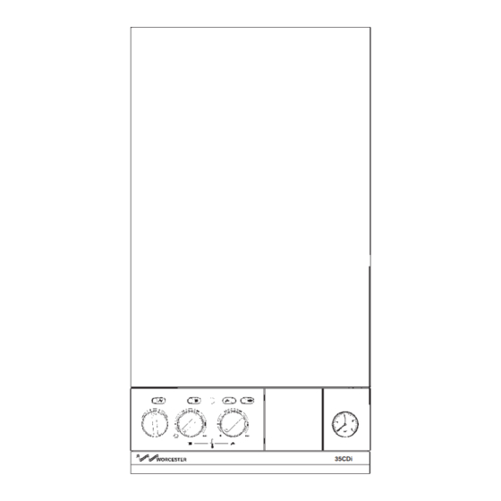
Contents Installation Regulations ..........Page 2 Electrical................ Page 8 Introduction..............Page 2 Installation..............Page 13 Technical Data .............. Page 4 Commissioning ............Page 17 Siting the Appliance ............ Page 6 User information............Page 19 Flue Terminal Position ..........Page 6 Inspection and Servicing .......... - Page 3 2. 6. Controls Fig. 1. Facia Controls 2.6.1. Control knob for switching the appliance On or Off. 2.6.2. Control knobs for adjusting the CH or DHW temperatures. 2.6.3. CH control knob switches the CH off and on. 2.6.4. A programmable room thermostat or a facia mounted programmer or clock is available.
-
Page 4: Technical Data
3. Technical Data Table 1. NOMINAL BOILER RATINGS (10 Minutes After Lighting) BOILER ADJUSTED FOR G20 (Natural Gas) BURNER SETTING OUTPUT INPUT (Net) GAS RATE PRESSURE Btu/h Btu/h m bar. in. wg. 30,700 11.42 38,900 1.19 41.98 25.0 85,300 28.52 97,300 2.97 104.8... - Page 5 Table 5 PERFORMANCE SPECIFICATIONS PRIMARY WATER CAPACITY 3.0 litres MAXIMUM MAINS INLET PRESSURE 10 bar MINIMUM MAINS INLET PRESSURE (working) for max. hot water flow 1.3 bar MINIMUM MAINS INLET PRESSURE (working) to operate appliance 0.8 bar MAXIMUM CENTRAL HEATING FLOW TEMPERATURE 82°C nom MAXIMUM CENTRAL HEATING SYSTEM SET PRESSURE 1.5 bar...
-
Page 6: Siting The Appliance
Fig. 3. Casing Dimension and Clearances 4. Siting the Appliance 4.1. The appliance may be installed in any room but refer to the requirements of the current IEE regulations and, in Scotland, the relevant electrical provisions of the Building Regulations with respect to the installation of appliances in rooms containing baths or showers. -
Page 7: Air Supply
5.3. The terminal must not cause an obstruction nor the Fig 6 - Sealed system combustion products a nuisance. 5.4. Under some climatic conditions the terminal might steam. Positions where this might be a nuisance should be avoided. Combustion products must not enter the roof space. 5.5. -
Page 8: Domestic Hot Water
8. Domestic Hot Water Fig 8 - System Make Up 8.1. If necessary reference should be made to the local water company before connecting the appliance. 8.2. Devices which would prevent the flow of expansion water must not be fitted unless separate arrangements have been made. - Page 9 10.10. On very rare occasions an external frost thermostat might Fig 9 - Mains Electrical Connection be considered where parts of the system are remote from the appliance. Refer to Worcester Heat Systems Technical Department for more information - Tel: 0990 266241. 10.11.
- Page 10 Fig 13 - Pictorial Wiring Diagram 2 Red 2 Orange Black White 6 Wires from Brown Bottom Green 1. Spark Generator Boiler 2. 6 Way In-Line Connector 3. 2 Way In-Line Connector 4. Gas Valve 5. Flow Switch 6. DHW Sensor 7.
- Page 11 Fig 14 - Functional Wiring Diagram Flame Demand Demand Detect Spark Indicator Indicator Indicator Electrodes Mains Indicator Green Electronics Spark Indicators Fuse F2 Regulator Valve (1.25A Slow) Main Valve Main Valve Transformer Pump Control Board MAIN CONTROL BOARD Fuse F1 Convert AC to low Flow Switch ST 12 Pin L...
- Page 12 Fig 17- Front View of Appliance (control panel removed) 1. Fan & Flow Sensor 2. Fan Connections 3. Combustion Products 1-Fig 22 2-Fig 23 30-Fig 55 4-Fig 57 Test Point 29-Fig 55 4. Overheat Thermostat 5. Air Pressure Switch 5-Fig 61 6.
-
Page 13: Installation
Fig 19- Side Flue Opening Position 11. Installation 11.1. General. 11.1.1. The appliance is suitable for sealed systems only. 11.1.2. The flue must be installed in accordance with BS5440:1. 11.2. Unpacking and appliance preparation 11.2.1. Remove the appliance from its packing and lay it on its back. - Page 14 Fig 21-Casing and Control Panel Fixing Screws Fig 22- Fan and Air Flow Sensor Fixing Negative 1.Transport Bracket and Bottom Panel Fixing Screws 2. Inner Casing Positive Fixing Screws 3. Control Panel Fixing Screws 1. Electrical connections 5. Air Flow Sensor 2.
- Page 15 11.7.6. Check that the gas and water valves are closed. Refer to Fig 26-Service Valve Operation Fig 26. 11.7.7. Lift the appliance onto the wall mounting plate/manifold assembly ensuring that the connections fully enter the manifold fittings after it is supported at the top. COLD 11.7.8.
- Page 16 11.8.3. Mark and cut the air and flue ducts to length. Always Fig 32-Flue Terminal and Duct Assembly check the dimensions before cutting. Do not cut the drilled or the expanded ends of the ducts. Make the cuts square and smooth. 11.8.4 Assemble the air and flue ducts and the terminal assembly as shown in the diagrams.
-
Page 17: Commissioning
Fig 34-Air Duct into Clamp Fig 35-Auto Air Vent 1. Auto Air Vent 1. Boiler Casing 2. Cap 3. Primary (CH) 2. Air Duct Sensor - Clamp Behind the Assembly Auto Air Vent 4. Flue Hood 3. Air Duct 5. Flue Hood Clamp 4. - Page 18 12.6. Remove the cap from the front of each pump and turn the Fig 38-Pumps exposed shaft about half a turn using a flat bladed screw driver. 1. Central Heating Replace the caps. Refer to Fig 38. Pump 12.7. Set the system pressure by filling the system until a 2.
-
Page 19: User Information
Balance the system so that the specified temperature difference 14. Inspection and Servicing is obtained. Shut the radiators and adjust the bypass until the same temperature difference is obtained. Refer to Fig 41. Set the room thermostat to minimum and check that the burner goes out and comes back on after a period of about three 14.1 The extent of the service required is determined by the minutes after the room thermostat is reset to maximum. -
Page 20: Replacement Of Parts
Fig 42-Flue Hood Fixing Fig 45-Burner Assembly 1. Burner Blade Assembly 5. Manifold Support Bracket Fixing Screw (2) 6. Burner Blade Locating 2. Burner Blade Assembly Screw 1. Clamp Location 3. Flue Hood 3. Burner Location Slot 7. Manifold Fixing Screw 2. - Page 21 Replace any components removed from the appliance in the Carefully pull off the leads at the electrode assembly. Unscrew reverse order using new gaskets/O-rings/sealant where the two screws and remove the spark electrode assembly from necessary. Always check that any electrical connections are the burner.
- Page 22 15.4.10. Flow Switch Fig 49-Domestic Hot Water Control Assembly Drain the hot water circuit. Refer to 15.3.2. Lower the facia. Separate the flow switch head in-line connector. Unscrew and Hexagonal head screw remove the flow switch head. Ensure that the new switch is 1.
- Page 23 Fig 51-System Pressure Switch 15.4.18. CH Sensor Remove the inner casing cover. Carefully pull off the connections and release the clip to remove 1. Pressure Switch the sensor. Apply heat transfer paste to the face of the new Body sensor. Refer to Fig 55. Note: If a left-hand flue is fitted then it is easier to remove the sensor and clip before pulling off the 2.
- Page 24 Fig 56-Domestic Hot Water Sensor Use new seals and gaskets where necessary. Refill and pressurise as described in Section 12.4-8 - Commissioning. Refer to Fig 59. 15.4.24. Auto Air Vent Remove the inner casing cover. Drain the primary system. Refer to 15.3.1. Unscrew and remove the auto air vent.
- Page 25 15.4.26. Air Pressure Switch Remove the inner casing cover. Carefully pull off the electrical connections and sensing tubes. Unscrew and remove the switch. Ensure that the connections are correctly made to the new switch. Refer to Fig 61. Fig 59-Domestic Hot Water Heat Exchanger Fig 60-Primary Heat Exchanger Fixing 1.
-
Page 26: Short Parts List
16. Short Parts List Description Manufacturer Number Number 8 716 156 733 0 E02-827 Gas Valve - NG Honeywell 8 716 156 734 0 E02-828 Gas Valve - LPG Honeywell 8 716 142 127 0 E02-825 Ignition Electrode Buccleugh 8 716 121 207 0 E02-892 Flame Sense Electrode Vernitron... -
Page 27: Operational Flow Diagrams
17. Operational Flow Diagrams Room CENTRAL HEATING FUNCTION thermostat and/or mains programmer (or link) On Electronic MAIN SWITCH Green Light facia programmer (if fitted) On ST13 link In CH control knob On CH light On. Two minute Pump On. minimum Modulate gas Pump Fan high... - Page 28 OVERRUN FUNCTION If heat Run pump demand has until primary occurred in drops to last 30 80°C minutes Within four minutes of last hot water demand primary temperature If heat above 80°C demand has Run fan If primary until primary temperature Run pump for occurred in...
-
Page 29: Fault Finding
The electronic control system for this appliance uses the four 18. Fault Finding lights on the facia. These show the normal operating status and, by flashing, help to provide a fault diagnostic system. With individual or groups of lights being permanently off, on or Note: This information is for guidance only. - Page 30 Is the facia on/off switch turned on? Turn switch on. `(Clockwise) Is there a 230V AC live supply across Check electrical Terminal ST12 pins L supply to boiler. and N Replace control board Has fuse F1 blown? (Section 15.4.12) Replace fuse and investigate cause. Suggestions: Cable damage, connections to (or faults within) pump, fan, external 230V controls, transformer or board.
- Page 31 Separate the 2 way in-line Remove multiway With a hot water tap connector to flowswitch connector from board Replace fully open, does the (fitted to boiler side position ST16. With Flow Switch boiler ignite and panel). With tap still open, tap still open is there appear to run is there continuity across...
- Page 32 Is the gas supply Rectify gas supply connected and at the problem. correct pressure? Remove front panel. Remove inner cover. Repair or replace Reset and restart the Reset and restart the Are the electrodes and electrodes boiler. Can a flame be boiler.
- Page 33 Is the multiway connector at board position ST16 pushed Push fully home. fully home on to the board? Remove multiway connector from board Separate 6 way in-line position ST16. Test Is there continuity connector and check resistance across from contacts 17 and continuity of red wires contacts 17 and 18 18 to DHW sensor?
- Page 34 Is the water pressure Re-pressurise boiler above 0.45 bar and/or check for leaks Remove fan connector from board position ST1 and restart boiler in the fault mode. After 5 seconds is Does this fault only there mains 230V Replace control board. occur in CH or DHW from the left (N) track (Section 15.4.12).
- Page 35 Light indication during fault not Control board is likely covered by above to be wet or damaged details. or malfunctioning. Check for wet board or connections. Dry and re-use or replace control board. (Section 15.4.12). Hot water sensor Hot water could be off or poorly temperature always fixed to pipe.
- Page 36 Bosch Group Worcester Heat Systems Limited, Cotswold Way, Warndon, Worcester WR4 9SW. Telephone: (01905) 754624. Fax: (01905) 754619. Technical Helpline (0990) 266241. This booklet is accurate at the date of printing but will be superseded and should be disregarded if specifications and/or appearances are changed in the interests of continued improvement.
Need help?
Do you have a question about the WORCESTER 35CDi and is the answer not in the manual?
Questions and answers