Emerson BETTIS G01 Series Disassembly And Reassembly
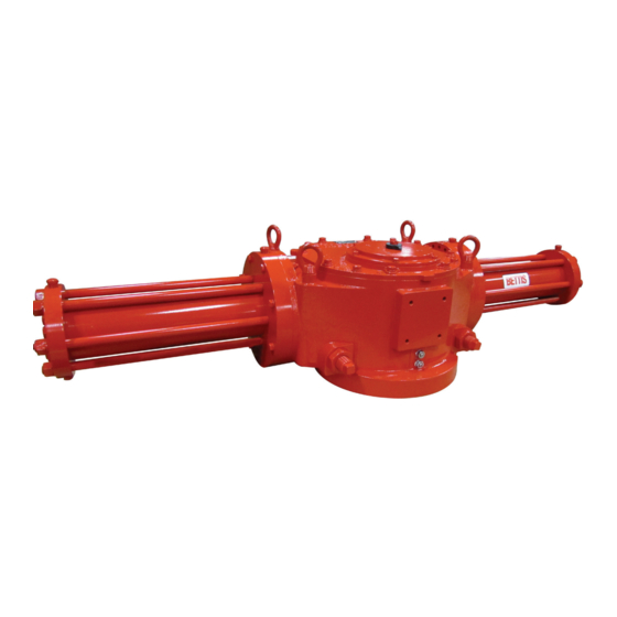
Hydraulic actuators spring-return actuators with m11 hydraulic override
Hide thumbs
Also See for BETTIS G01 Series:
- Installation, operation and maintenance manual (64 pages) ,
- Installation, operation and maintenance manual (18 pages)

Related Manuals for Emerson BETTIS G01 Series


Summary of Contents for Emerson BETTIS G01 Series
- Page 1 Service Instructions 127072E Rev. C October 2015 G01 through G10 Series Hydraulic Actuators Spring-Return Actuators with M11 Hydraulic Override Disassembly and Reassembly...
-
Page 3: Table Of Contents
Service Instructions Table of Contents 127072E Rev. C October 2015 Table of Contents Section 1: Introduction General Service Information ................1 Definitions ....................1 General Safety Information ................2 Bettis Reference Materials ................2 Service Support Items ................... 3 Lubrication Requirements ................3 Fluid Requirements .................. - Page 4 Table of Contents Service Instructions October 2015 127072E Rev. C Section 6: Actuator Support Information Module Volume Table ................. 31 Module Weight Tables ................. 31 G01 Tool Table .................... 33 G2 Tool Table ....................33 G3 Tool Table ....................34 G4 Tool Table ....................
-
Page 5: Section 1: Introduction
1�1�10 Use a non-hardening thread sealant on all pipe threads. CAUTION: FOLLOW MANUFACTURER'S INSTRUCTIONS Apply the thread sealant per the manufacturer’s instructions. 1�1�11 Emerson recommends that disassembly of the actuator modules should be done in a clean area on a work bench. 1�2... -
Page 6: General Safety Information
1�3 General Safety Information 1�3�1 Products supplied by Emerson, in its "as shipped" condition, are intrinsically safe if the instructions contained within this service instruction are strictly adhered to and executed by well-trained, equipped, prepared and competent personnel. WARNING: READ WARNING MESSAGES CAREFULLY For the protection of personnel working on Bettis actuators, this procedure should be reviewed and implemented for safe disassembly and reassembly. -
Page 7: Service Support Items
1�7�1�1 Standard temperature service (-20°F to +350°F)/(-28.9°C to +176.6°C) use Shell Tellus S2 V grade 32 automatic transmission fluid or an Emerson approved fluid. 1�7�1�2 High temperature service (0°F to +350°F)/(-17°C to +176.6°C) use Shell Tellus S2 V grade 32 automatic transmission fluid or an Emerson approved fluid. -
Page 8: General Tool Information
Section 1: Introduction Service Instructions October 2015 127072E Rev. C 1�8 General Tool Information 1�8�1 Tools: All tools/hexagons are American Standard inch. Large adjustable wrench, two (2) large screwdrivers, Allen wrench set, set of open/box end wrenches, rubber or leather mallet, torque wrench (up to 1200 foot pounds / 1627 N-m), breaker bar, and a drive socket set. -
Page 9: Actuator Operation
Section 1: Introduction Service Instructions 127072E Rev. C October 2015 Indicated position confirms valve position All switching valves in normal operating position as per schematic/ instructions 1�11�2 Check connections: Hydraulic components connected as per schematic enclosed or in service manual supplied Hydraulic supply connected to identified ports Electrical connections terminals are secure Wiring as per enclosed diagram or service manual supplied... -
Page 10: Section 2: Actuator Disassembly
Section 2: Actuator Disassembly Service Instructions October 2015 127072E Rev. C Section 2: Actuator Disassembly 2�1 General Disassembly WARNING: DANGEROUS GAS AND/OR LIQUIDS It is possible that the actuator may contain a dangerous gas and/or liquids. Ensure that all proper measures have been taken to prevent exposure or release of these types of contaminants before commencing any work. -
Page 11: Drive Module Disassembly
Service Instructions Section 2: Actuator Disassembly 127072E Rev. C October 2015 WARNING: CHECK SPRING COMPRESSION The spring cartridge must be checked to verify that the spring(s) are in their extended position before the hydraulic power module is disassembled from the drive module (refer to Section 5.1 through step 5.1.6). - Page 12 Section 2: Actuator Disassembly Service Instructions October 2015 127072E Rev. C For steps 2.3.3 through 2.3.10 refer to assembly drawing page 2 of 2 Section A-A and Detail “F”. 2�3�3 Before removing position indicator (1-220), record or mark its position. Remove position indicator (1-220).
- Page 13 Service Instructions Section 2: Actuator Disassembly 127072E Rev. C October 2015 2�3�16 Rotate the arms of yoke (1-70) to the center position of housing (1-10). 2�3�17 Remove yoke (1-70) with yoke pin (1-80), guide block (1-30), two yoke/guide block bushings (2-30) by lifting yoke up and out of the housing (1-10). 2�3�18 Remove bottom yoke pin thrust bearing (2-10) from inside bottom of housing (1-10).
-
Page 14: G01 Through G5 M11 Hydraulic Override Cylinder Disassembly
Section 2: Actuator Disassembly Service Instructions October 2015 127072E Rev. C 2�4 G01 through G5 M11 Hydraulic Override Cylinder Disassembly NOTE: For M11 hydraulic override cylinder removal from spring cartridge refer to Section 5 step 5.1. 2�4�1 Unscrew hydraulic ram cover (7-10) from hydraulic override end cap (7-70). 2�4�2 Remove hydraulic ram (7-20) from hydraulic ram cover (7-10). -
Page 15: Section 3: Actuator Reassembly
Service Instructions Section 3: Actuator Reassembly 127072E Rev. C October 2015 Section 3: Actuator Reassembly 3�1 General Reassembly CAUTION: ONLY USE NEW SEALS Only new seals, that are still within the seals expectant shelf life, should be installed into actuator being refurbished. 3�1�1 Remove and discard all old seals and gaskets. - Page 16 Section 3: Actuator Reassembly Service Instructions October 2015 127072E Rev. C NOTE: The guide bar bearing (2-20) must be pressed fit into guide block guide bar bore with the seam located 45 ±5 degrees of the top or bottom centerline as shown in section A-A. For G01 model actuators skip steps 3.2.2 through 3.2.13 and continue reassembly at step 3.2.14.
- Page 17 Service Instructions Section 3: Actuator Reassembly 127072E Rev. C October 2015 NOTE: The spherical side of the washer will go on the extension rod assembly facing the head of the extension rod assembly. 3�2�11 Install extension rod assembly (9-50) into guide block (1-30) and up against the first spherical washer (9-40).
- Page 18 Section 3: Actuator Reassembly Service Instructions October 2015 127072E Rev. C NOTE: The yoke pin can be held in place by installing a screw into the .375 16 UNC tapped hole in the upper end of yoke pin (1-80). 3�2�21 Install yoke pin (1-80) by inserting into the upper yoke arm, upper yoke/guide block bushing, guide block, lower yoke/guide block bushing, lower yoke arm and resting on lower yoke pin thrust bearing (2-10).
- Page 19 Service Instructions Section 3: Actuator Reassembly 127072E Rev. C October 2015 3�2�30 Torque tighten hex cap screws (1-110) until a final lubricated torque, as listed in the following table, has been achieved. Table 2� Housing Cover Screw Quantity and Torque TORQUE (±5%) TORQUE (±5%) Model...
-
Page 20: Hydraulic Power Module Reassembly
Section 3: Actuator Reassembly Service Instructions October 2015 127072E Rev. C NOTE: Refer to Section 2 step 2.3.3 for correct position indicator placement. Install position indi- cator (1-220) over the exposed shaft of position indicator assembly (1-140). 3�2�42 Install stop screw nuts (1-190) onto stop screws (1-180). 3�2�43 Install O-ring (2-90) onto stop screws (1-180). - Page 21 Service Instructions Section 3: Actuator Reassembly 127072E Rev. C October 2015 3�3�11 Coat one piston seal (4-60) with fluid and install into the piston external seal groove. CAUTION: INSTALL PISTON SEAL CORRECTLY Install the piston seal with energizer ring facing the outside edge of piston (3-30). 3�3�12 Refer to assembly drawing page 2 of 2 Detail "C".
-
Page 22: G01 Through G5 M11 Hydraulic Override Cylinder Reassembly
Section 3: Actuator Reassembly Service Instructions October 2015 127072E Rev. C 3�3�24 If the power module is reassembled off the actuator then refer to Section 5 step 5.4 for hydraulic power module installation instructions. 3�4 G01 through G5 M11 Hydraulic Override Cylinder Reassembly NOTE: Review Section 3.1 General Reassembly before proceeding with G01 through G5 M11... - Page 23 Service Instructions Section 3: Actuator Reassembly 127072E Rev. C October 2015 NOTE: The lip of Polypak seal (8-30) will face toward the hydraulic override end cap when installed in the hydraulic cylinder assembly. 3�5�2 Install rod bushing (8-20) into hydraulic cylinder assembly (7-10). 3�5�3 Install rod wiper (8-10) into hydraulic cylinder assembly (7-10).
-
Page 24: Actuator Testing
The actuator's main pressure bearing parts will be tested in controlled conditions by pressuring both sides of the piston to avoid damage and over torquing of the actuator components. If further future testing in the field is necessary, Emerson should be contacted for guidance. -
Page 25: Section 4: Field Conversions
Service Instructions Section 4: Field Conversions 127072E Rev. C October 2015 Section 4: Field Conversions 4�1 Fail Mode Reversal (CW to CCW or CCW to CW) 4�1�1 Remove spring module per Section 5.3. 4�1�2 Remove hydraulic power module per Section 5.5. 4�1�3 Reinstall the spring module onto the opposite end of housing (1-10) as it was previously located per Section 5.4. -
Page 26: Section 5: Module Removal And Installation
Section 5: Module Removal and Installation Service Instructions October 2015 127072E Rev. C Section 5: Module Removal and Installation 5�1 M11 Override Cylinder Removal 5�1�1 Shut off and exhaust the operating media from both sides of the actuator’s power cylinder. 5�1�2 Place the M11 pump control knob (20-320) in the auto position. -
Page 27: M11 Override Cylinder Installation
Service Instructions Section 5: Module Removal and Installation 127072E Rev. C October 2015 NOTE: To identify hex cap screws (7-100) from hex cap screws (7-80), hex cap screws (7-100) will be located to the left and right of spring-return cartridge top dead center and will then be counted as every other hex cap screw. -
Page 28: Spring Module Removal
Section 5: Module Removal and Installation Service Instructions October 2015 127072E Rev. C 5�2�6 Using pipe dope on threads reinstall all piping between hydraulic override cylinder assembly and the M11 pump. 5�2�7 Fluid filling instructions for M11 and M11-S hydraulic override systems: 5�2�7�1 To fluid fill M11 manual hydraulic override system refer to instructions part number 126858. -
Page 29: Spring Module Installation
Service Instructions Section 5: Module Removal and Installation 127072E Rev. C October 2015 5�3�7 The spring cartridge "pre load" must be removed before spring cartridge (5-10) is removed from housing (1-10). Refer to steps 5.3.4 through 5.3.6 for spring cartridge "pre-load" removal. CAUTION: OBSERVE CORRECT OPERATING PRESSURE The maximum pressure to be applied in step 5.3.8 is 25 PSIG. - Page 30 Section 5: Module Removal and Installation Service Instructions October 2015 127072E Rev. C NOTE: The setting of stop screws (1-180) should be checked and setting recorded before stop screws are loosened or removed. 5�4�1 On stop screw (1-180), that is located on the same side of the housing as spring cartridge (5-10), loosen stop screw nut (1-190).
-
Page 31: Hydraulic Power Module Removal
Service Instructions Section 5: Module Removal and Installation 127072E Rev. C October 2015 5�4�6 Torque tighten the spring cartridge tension rod as listed in the following table. Table 7� Spring Cartridge Tension Rod Torque Table TORQUE (±5%) TORQUE (±5%) Housing Housing Model Model... -
Page 32: Hydraulic Power Module Installation
Section 5: Module Removal and Installation Service Instructions October 2015 127072E Rev. C NOTE: Review Section 2.1 General Disassembly before proceeding with the hydraulic power mod- ule disassembly. Use a means of capturing the hydraulic fluid that will be lost during the following steps. Use a bucket, tub, and large container, etc. -
Page 33: G2 Through G10 Powr Swivl™ Removal
Service Instructions Section 5: Module Removal and Installation 127072E Rev. C October 2015 5�7 G2 through G10 Powr Swivl™ Removal 5�7�1 Push the guide block to the side of housing (1-10) that will expose the extension rod assembly (1-50). NOTE: The guide block can be moved by inserting a long non-metallic rod through the hole where the blind end cap was removed and pushing on the guide block. - Page 34 Section 5: Module Removal and Installation Service Instructions October 2015 127072E Rev. C NOTE: The spherical side of washer (1-40) will be facing the outside of guide block (1-30). Install second spherical washer (1-40) over threaded end of extension rod 5�8�4 assembly (1-50).
-
Page 35: Section 6: Actuator Support Information
Service Instructions Section 6: Actuator Support Information 127072E Rev. C October 2015 Section 6: Actuator Support Information 6�1 Module Volume Table Table 9� M11 Hydraulic Override System Fluid Volume Table ACTUATOR SIZE Quarts 10.2 15.9 27.0 APPROX� VOLUME FLUID FOR M11 SYSTEM Liters 15.1... - Page 36 Section 6: Actuator Support Information Service Instructions October 2015 127072E Rev. C ITEM DESCRIPTION NO� WT� WT� WT� WT� WT� WT� WT� WT� 9.0” Dia. Power Module 10.0” Dia. Power Module 12.0” Dia. Power Module 1104 14.0” Dia. Power Module 16.0”...
-
Page 37: G01 Tool Table
Service Instructions Section 6: Actuator Support Information 127072E Rev. C October 2015 6�3 G01 Tool Table Table 11� G01 Tool Style and Wrench Size ITEM ITEM LOCATION OR RECOMMENDED WRENCH SIZE NO� QTY� DESCRIPTION TOOL STYLE 1-110 9/16” Cover Screws Socket 1-160 1/2”... -
Page 38: G3 Tool Table
Section 6: Actuator Support Information Service Instructions October 2015 127072E Rev. C 6�5 G3 Tool Table Table 13� G3 Tool Style and Wrench Size ITEM ITEM LOCATION OR RECOMMENDED WRENCH SIZE NO� QTY� DESCRIPTION TOOL STYLE 1-110 9/16” Cover Screws Socket 1-160 9/16”... -
Page 39: G5 Tool Table
Service Instructions Section 6: Actuator Support Information 127072E Rev. C October 2015 6�7 G5 Tool Table Table 15� G5 Tool Style and Wrench Size ITEM ITEM LOCATION OR RECOMMENDED WRENCH NO� SIZE QTY� DESCRIPTION TOOL STYLE 1-110 3/4” Cover Screws Socket 1-120 3/4”... -
Page 40: G8 Tool Table
Section 6: Actuator Support Information Service Instructions October 2015 127072E Rev. C 6�9 G8 Tool Table Table 17� G8 Tool Style and Wrench Size ITEM ITEM LOCATION OR RECOMMENDED WRENCH NO� SIZE QTY� DESCRIPTION TOOL STYLE 1-110 3/4” Cover Screws Socket 1-120 3/4”... -
Page 41: Section 7: Troubleshooting
In the unlikely event of a fault developing, the following Fault Location Table is provided to assist the service engineer to perform troubleshooting. This table is designed to cover as wide a range of Emerson Bettis actuators as possible. Reference to equipment not supplied should be ignored. -
Page 42: Operational Test
Section 7: Troubleshooting Service Instructions October 2015 127072E Rev. C 7�2 Operational Test 7�2�1 Full Stroke Test The “full stroke test” (“On-line”) must be performed to satisfy the PFD (average probability of failure on demand) value. The full stroke test frequencies will be defined by the final installer to achieve the defined SIL level. -
Page 43: Section 8: Removal And Decommissioning
If a conflict arises between this procedure and the customer's procedures, the differences should be resolved in writing between an authorized customer’s representative and an authorized Emerson/Bettis representative. CAUTION: ISOLATE AND POWER OFF ACTUATOR Make sure actuator is isolated before removing from valve. Turn off the power medium and bleed off all pressure first, including storage tank (if present). -
Page 44: Section 9: Document Revision
Table 20� Revision Overview DATE REVISION STATUS BY * DATE Released December 2001 B. Cornelius December 2001 19110 July 2006 UPDATED C. Ross July 2006 VAWCO2794 October 2015 UPDATED C. Rico October 2015 *Signatures on file Emerson, Houston, Texas Document Revision... -
Page 45: Appendix A: List Of Tables
Service Instructions Appendix 127072E Rev. C October 2015 Appendix A: List of Tables Table 1. Actuator Model and Part Number ................3 Table 2. Housing Cover Screw Quantity and Torque ............15 Table 3. Tie Bar Nuts (3-90) Torque Table ................17 Table 4. -
Page 46: Appendix B: List Of Drawings
Appendix Service Instructions October 2015 127072E Rev. C Appendix B: List of Drawings B�1 Part No� 122588, G1/2/3/4/5-SRX-H Hydraulic Assembly Drawing, Sheet 1 of 2 Appendix... - Page 47 Service Instructions Appendix 127072E Rev. C October 2015 B�2 Part No� 122588, G1/2/3/4/5-SRX-H Hydraulic Assembly Drawing, Sheet 2 of 2 Appendix...
- Page 48 Appendix Service Instructions October 2015 127072E Rev. C B�3 Part No� 126567, M11 Assembly Drawing, Sheet 1 of 5 Appendix...
- Page 49 Service Instructions Appendix 127072E Rev. C October 2015 B�4 Part No� 126567, M11 Assembly Drawing, Sheet 2 of 5 Appendix...
- Page 50 Appendix Service Instructions October 2015 127072E Rev. C B�5 Part No� 126567, M11 Assembly Drawing, Sheet 3 of 5 Appendix...
- Page 51 Service Instructions Appendix 127072E Rev. C October 2015 B�6 Part No� 126567, M11 Assembly Drawing, Sheet 4 of 5 Appendix...
- Page 52 Appendix Service Instructions October 2015 127072E Rev. C B�7 Part No� 126567, M11 Assembly Drawing, Sheet 5 of 5 Appendix...
- Page 53 Service Instructions Appendix 127072E Rev. C October 2015 B�8 Part No� VA-ED-000-8765-00, G7/8/10-SRX-H Hydraulic Assembly Drawing, Sheet 1 of 2 Appendix...
- Page 54 Appendix Service Instructions October 2015 127072E Rev. C B�9 Part No� VA-ED-000-8765-00, G7/8/10-SRX-H Hydraulic Assembly Drawing, Sheet 2 of 2 Appendix...
- Page 55 Service Instructions Appendix 127072E Rev. C October 2015 B�10 Part No� 121107, Remote Mount Assembly Drawing for M11-S G4/G8 Fire Safe, Sheet 1 of 2 Appendix...
- Page 56 Appendix Service Instructions October 2015 127072E Rev. C B�11 Part No� 121107, Remote Mount Assembly Drawing for M11-S G4/G8 Fire Safe, Sheet 2 of 2 Appendix...
- Page 58 Tianjin 301700 Holland Fasor 6 P. R. China Székesfehérvár 8000 The Emerson logo is a trademark and service mark of Emerson Electric Co. T +86 22 8212 3300 Hungary Bettis is a mark of one of the Emerson family of companies.
Need help?
Do you have a question about the BETTIS G01 Series and is the answer not in the manual?
Questions and answers