
Related Manuals for Marine PC MIL-Spec MPC-ML2 D Series

Summary of Contents for Marine PC MIL-Spec MPC-ML2 D Series
- Page 1 MARINE PC MARINE PC MPC-ML2xxD MIL-Spec LCD Displays User Manual www.MarinePC.com...
- Page 2 Owner Record Here is an easy-to-locate form to record the unit’s serial number, and from the invoice, record the invoice date. The unit’s serial number is located on the back panel. If the unit ever requires service, please refer to this information when contacting the MarinePC Service Center.
- Page 3 MPC-ML2xxD Military Grade All-Weather LCD Displays User Manual www.MarinePC.com MPC-ML2D-UM(B) 10/2015...
-
Page 4: Table Of Contents
Table of Contents Introduction ..........................Safety .............................. Product Care and Maintenance .................... System Set-up........................... Installation ..........................Cable Connections........................Computer Hook-up ........................ Operator Controls ........................On-Screen Display (OSD) ...................... Optional USB Pass-Through ....................Optional Touch Screen Display ..................Appendix A - Mechanical Drawings ................ -
Page 5: Introduction
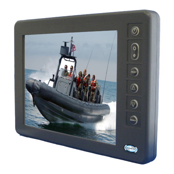
Welcome. The Marine PC MIL-Spec Monitor (MPC-ML2D) is a ruggedized marine grade LCD Dis- play for use with a digital video (DVI-D) computer input. It is designed to operate under the most extreme environments found in high performance vessels such as public safety, government and military marine craft, as well as submarine vessels. -
Page 6: Safety
Safety General Safety Instructions • Before operating the MPC-MLD Monitor, read this User Manual thoroughly • Retain this User Manual for future use • Verify the computer system capability (see System Set-up) to insure operation of the Monitor • For expeditious installation, follow these User Manual instructions in the sequence presented • Adhere to all Caution and Warnings on system parts and as stated in this User Manual • All User Manual instructions for installation and operation must be followed precisely • Adjust only those controls covered by the User Manual’s operating instructions; improper adjustment of other controls voids the unit’s warranty and may result in unit damage, and • Adhere to local installation codes. Safety Icons Warning! Shock Hazards This icon is intended to tell you of a potential risk of electrical shock. - Page 7 Fluids from LCD Display CAUTION! • If the Monitor should ever become shattered, do not touch fluids from an LCD Display • If fluid should get on hands or clothing, immediately wipe off with liquid soap or rubbing alcohol; wash with water; consult with a doctor, and • If fluid gets in the eyes, flush eyes immediately with water for a minimum of 15 minutes; Electrical Safety Connecting Cables • Disconnect the power to the computer when the Monitor is being installed, and • Upon installation, verify the power connector is securely seated on the unit. Ratings and Grounding This unit may be operated from an 10-38 VDC power source. • Use the supplied power cable, and • Always connect to a properly grounded power source. Protection on Servicing Servicing - User • User care is limited to cleaning the exterior of the unit. • Do not disassemble or modify the unit or cables to avoid the possibility of an electrical shock, damage to electrical components or scratching the Display surface, and • Disassembly or modification voids the warranty.
-
Page 8: Product Care And Maintenance
PRODUCT CARE AND MAINTENANCE Product Care This MPC-MLD Monitor has been designed to provide optimum performance and service without any required scheduled maintenance other than occasional cleaning. Turn off the Monitor power before cleaning the Monitor, optional Touch Screen or unit’s enclosure. WARNING! • Do not use abrasive cleaners or solvent-based (flammable) cleaners on the Flat Panel or Touch Screen Display, its enclosure or any other electrical de- vice (cables, power cord, etc) CAUTION! • Do not use paper products as they may scratch the Display screen, and • Do not directly apply cleaning solutions to the Display screen. - Page 9 To avoid risk of electrical shock, do not disassemble the unit’s enclosure. Users cannot service the Monitor. User maintenance is restricted to cleaning, as ex- plained. Disassembling the unit voids the warranty. WARNING! Long-term Storage • For long-term storage, it is suggested the unit be stored in a normal indoor environment and the Display glass be protected from accidental damage. • For pedestal mount units, disconnect the cable(s) and loosen the arm adjustment to a point where the ball can be removed from the arm, or • For Flush or Panel Mount units, cover the product with a protective covering that...
-
Page 10: System Set-Up
SYSTEM SET-UP System Requirements The computer the MPC-MLD shall be connected to must have this capability: • Video card setting with a minimum resolution of 640 x 480 pixels, and • If the optional Touch Screen Display is ordered, an available USB or COM port for the connector is required. Shipping Box Contents The MPC-MLD is shipped in a custom box with custom foam packaging. We recommend you save the box and all packaging materials in case the unit would need to be returned to the MarinePC Service Center. -
Page 11: Installation
INSTALLATION The MPC-MLD is designed to be mounted with a universal ball-and-socket mounting kit, or in a Surface Panel Mount configuration. Pedestal Mount The MPC-MLD is shipped with a RAM® universal ball-and-socket system mounting kit (Figure 2). By installing the Monitor with this kit, the user can quickly adjust the viewing angle to improve viewability in changing environments. This ball-and-socket system has proven to be successful in supporting an extreme amount of weight in high vibration and difficult-mount applications. See Appendix A for link to drawings. - Page 12 There are three mounting holes in the back of the Monitor for the ball mounting plate. Take care not to strip the screw holes or over tighten. (Figure 4) • Line up one of the ball mounting plates on these three holes (Figure 4) • With three (3) M4 x 10 counter-sunk stainless screws attach this mounting plate to the back of the MPC-MLD. • Mount the second ball mounting plate where the Monitor shall be installed • Insert each ball into the RAM arm • Lightly tighten the arm around the balls using the T-knob on the arm (Figure 2, 4) • Adjust the Monitor to the viewing preference, and • Tighten the T-knob to hold the Monitor in position. It is recommended the remaining ball be mounted on a flat surface. Because of the various surface substrates the Monitor shall be mounted on, the installer shall provide the screws to mount the other ball.
-
Page 13: Cable
DISPLAY CONNECTIONS Connectors Use care when inserting or removing connector. Do not force their mating. CAUTION! There are two (2) MIL-DTL connectors on the MPC-MLR: Power Input and Video Input. (Figure 6, 7). Connectors are located on bottom of Display housing. From left to right: Power Input, a 3-Pin Connector and Video Input, a 13-Pin Connector. Power Input Video Input Figure 6 Figure 7 Power Input The Power Amphenol Connector is a MIL-DTL-26482 POWER CABLE Series I Connector. 3-PIN PLUG MIL-C-26482 SERIES I • End User supplied or Optional Power Cable SIGNAL... - Page 14 Video Input The Video Amphenol Connector is a MIL-DTL-38999 Series I Connector. See Table 2. • End User supplies Video Cable or Supplied With Unit • 19-Pin Connector pin-out is listed in Table 2 • Line up with Connector # 2 in Figure 6 • Add a twist to lock. DVI-D J2 19-PIN PLUG SIGNAL DVI RX2+ DVI RX2- DVI RX1+ USBD0+/RS232 RXD USBD0-/RS232 TXD DVI RX1- GROUND REMOTE ON/OFF (OPTIONAL) GROUND DVI +5V DVI RX0+ DVI RX0- DVI HOT PLUG DETECT DVI DDC SDA DVI RXC+ GROUND...
-
Page 15: Computer Hook-Up
COMPUTER HOOK-UP Computer Display Properties - XGA or SVGA Prior to connecting the MPC-MLD to the computer, with another monitor, verify the computer display properties are set to between 640x480 and 1280x1024 in 4:3 aspect ratio. • The optimum setting for viewing is 800 x 600 (8.4”) or 1024x768 pixels (all other sizes). • The refresh rate must be set between 60-75Hz to eliminate screen flicker. • Pixel settings different from the native resolution may exhibit less precise images, and CAUTION! • Pixel settings over 1280 x 1024 flash “out of range”, with no display. - Page 16 Select the Monitor tab. Under Monitor Settings, verify the Screen Refresh Rate is between 60 and 75Hz. • If so, select the Cancel button and go to step 9. • If not, select a setting within the 60 – 75Hz range • Select the Apply button. At the Monitor Settings dialog box, select “Yes” to accept the new desktop view settings.
- Page 17 Signal Quality • The strength of the video signal provided to the MPC-MLD Monitor has a direct bear- ing on the quality of the images displayed • The cable supplied with the unit shall provide the optimum image if proper wiring practices are followed • Install the cable properly and keep it away from sources of EMI such as electric motors, or unshielded RF sources such as radar and microwaves • Splitting the video signal also splits the strength of the signal • If your installation requires more than one Monitor to be driven from a single video source, it is highly recommended that a video signal booster (line driver) be used in the circuit, and • Some splitters are available with an integral line driver. Whether or not a line driver is used, single cable lengths in excess of our standard cable length should be of high quality shielded DVI cable.
-
Page 18: Operator Controls
OPERATOR CONTROLS On the right hand side of the Monitor bezel are seven Operator Control buttons. Power On/Off (I/O) Button Power Button Note: Monitor defaults to an AUTO-OFF state when Brightness Control Toggle power is applied. (large sun, small sun) • The Power On/Off button is marked with the I/O (Input/Output) symbol • Momentarily pressing this button shall Select Button turn ON or turn OFF the unit, and • Blue LEDs glow behind the buttons when the unit is powered on. -
Page 19: On-Screen Display (Osd)
ON-SCREEN DISPLAY The On-Screen Display (OSD) user interface is the path to all display signal source adjustments. The Source Screen Menu, with its user-friendly graphical interface, provides access to fine-tuning the Display. OSD Source Screen Menu Activation To activate the OSD menu in the current video source, press and release the SELECT button. - Page 20 OSD Source Screen Menu Parameter Selections • New settings shall be stored in memory upon pressing the SELECT button to exit the Source OSD Source Screen Category’s Function Menu. CAUTION! • If SELECT is not pressed, or inactivity is detected within the 15 second factory default OSD duration, any function adjustments made shall not be saved. It is recommended to adjust the LED back light brightness to maximum before fine-tuning the OSD Source Screen Menu Picture Menu Parameter: Brightness. Picture Menu Parameters Brightness Before adjusting the Brightness function parameters, set the LCD panel backlight...
- Page 21 Source Menu Parameters A check in a box indicates an enabled signal source attached to the Monitor. Deselecting the box disables the Monitor’s ability to display the signal. Video 1 - Composite • Open the “Video1“ function, and • Press the UP or DOWN buttons to enable (ON) or disable (OFF) the Video 1 source. Video 2 – INACTIVE or, if connected, as above. Video 3 - INACTIVE or, if connected, as above. PC - VGA • Open the “PC“ function, and • Press the UP or DOWN buttons to enable (ON) or disable (OFF) the PC source.
- Page 22 contrast, saturation, tint and sharpness. System • Select “System“ function to select the source signal type: NTSC, PAL and AUTO • Video 1 - Composite - NTSC • Video 2 - Inactive • Video 3 - Inactive • PC – RGB, and • AUTO - Recommended selection. Automatically assigns the correct video signal source association. TV Category Parameters - INACTIVE Screen Menu Parameters NOTE: Source Screen Menu Category is enabled when the input signal is VGA. H-Position • Open the “H-Position” function, and • Press the UP or DOWN buttons to adjust the horizontal position of the screen display. V-Position • Open the “V-Position” function, and • Press the UP or DOWN buttons to adjust the vertical position for the screen display. Phase • Open the “Phase” function, and • Press the UP or DOWN buttons to adjust phase (analog to digital) for the screen display.
-
Page 23: Optional Usb Pass-Through
NOTES MPC-ML2D-UM(B) 10/2015... -
Page 24: Optional Touch Screen Display
OPTIONAL TOUCH SCREEN MPC-MLR Optional Touch Screen Installation If you are installing a new operating system (O/S), do not install the Touch Screen Controller Driver CD until you have installed the O/S and verified the computer’s monitor display is working properly. The Touch Screen Controller Driver uses the CAUTION! computer’s O/S display driver software settings to accurately configure the Touch Screen Controller Driver files. - Page 25 Uninstall a Previous Version of Other Touch Screen Drivers If a version of a different Touch Screen Controller Driver (not TSHARC) is on the com- puter, it must be completely removed before installing the TSHARC. Note: The typical driver uninstall program or Microsoft’s® remove program utility does not remove all tracks of the Touch Screen Driver program. Contact the manufacturer of the previ- ously installed driver program to learn how to completely uninstall their product.
- Page 26 TSHARC Installation If you need to cancel this driver installation at any time, select the Cancel button on the driver installation dialog screen. CAUTION! 1. At the Welcome screen, select Next to go to the Software License Agreement (EULA) 2. After reading the EULA, if in agreement, check the box “I accept all of the terms…”...
- Page 27 Manual RS-232 Controller Set-up 1. Select the Controller Interface RS-232 radio button 2. Select Next Note: Do not select Autodetect 3. Follow the instructions, entering the COM port selection 4. The Touch Screen Controller baud rate default is 9600 Note: Capacitive Controller option is not available. 5.
- Page 28 Calibration The calibration process aligns the Touch Screen overlay to specific points on the Display screen. 1. Select the Calibration tab or, in ten seconds, the calibration program launches, unless a Multi-monitor situation is present, then go to section Configuring a Multi-monitor Installation 2.
- Page 29 Calibration Drawing Test 1. Select the Test button on the Calibration tab 2. Using a finger or stylus, draw or write, and 3. Observe if the screen displays the drawing accu- rately. If it does not, repeat the Custom Calibration Settings and Calibration Process instructions Click Settings Right Click...
- Page 30 Capacitive Tab – Disabled The Touch Screen is a resistive type; the Capacitive Tab shall be disabled. Touch Screen Tray Icon 1. If you do not want a Touch Screen Controller Icon to display in the toolbar tray, go to step 3, or 2. If you want a Touch Screen Controller Icon to display in the toolbar tray, select the box, and 3. Select the Finish button; the TSHARC drivers shall be installed.
-
Page 31: Appendix A - Mechanical Drawings
APPENDIX A Mechanical Drawings Mount diagrams of the MPC-MLD and its dimensions may assist you in installation of the Monitor. You may find them on our website at: http://www.marinepc.com/products/purchased model and size Mount diagrams of the optional Flush Mount Bezel and its dimensions may assist you in installation of the Monitor. You may find them on our website at: http://www.marinepc.com/products/purchased size APPENDIX B Display... - Page 32 Symptom: Display has rolling “bars” across the screen or vertical shaded bars on the image. Possible Problem Solution VGA video display is not set to view at 800 x Verify the computer video display settings of 600 pixels, or 1024x768 pixels. the signal are set to match the display and 60 - 75Hz refresh rate. Defective video cable On a known good display source, confirm the video cable is not defective.
- Page 33 Symptom: Display image is not properly sized Possible Problem Solution OSD adjustments need to be made Adjust the vertical and horizontal size controls through the OSD. Improper video display settings Check for proper display properties selection of the display settings. Monitor autosize will only display full screen if source is 4:3 aspect ratio.
- Page 34 APPENDIX C Technical Specifications 8.4” 10.4” 12.1” 15” TFT AM, SVGA, LCD, 1024 x 768 XGA OPTIONAL OPTIONAL Display Display 262K Colors. 800 x 600 pixels 1024 x 768 XGA 1024 x 768 Display XGA Display 700 nits 700 nits 550 nits Sunlight 1,000 nits Readable MIL-L-85762A (AF-Open Canopy) (1,000 nits) (1,000 nits) Dimming ...
-
Page 35: Appendix C -Technical/Environmental Specifications
Environmental Specifications 8.4” 10.4” 12.1” 15” -40°C to 70°C (-40°F to 158°F) Operating Temperature MIL-STD-810F: 501.4/502.4: II-Op Storage Tem- -40°C to 75°C (-40°F to 167°F) perature Shock 50 G Vibration 5.8 G (5-500 Hz) Altitude 45,000 ft. ... - Page 36 Warranty Terms and Conditions offers it’s products and services MarinePC cancellation charges will apply to any and for sale under the following terms and con- all unshipped items. Partial credit may be ditions. Any and all orders will be accepted extended if products are returned unused only at the sole discretion of MarinePC...
Need help?
Do you have a question about the MIL-Spec MPC-ML2 D Series and is the answer not in the manual?
Questions and answers