Advertisement
Quick Links
INSTALLATION AND MAINTENANCE INSTRUCTIONS
INSTALLATION AND MAINTENANCE INSTRUCTIONS
SK-Control
Supervised Control Module
SPECIFICATIONS
Normal Operating Voltage:
15 to 32 VDC
Maximum Current Draw:
6.5 mA (LED on)
Average Operating Current:
375 µA (LED flashing - in group poll mode) 350 µA (LED flashing - in direct poll mode) 485 µA Max. (LED flashing, NAC shorted)
Maximum NAC Line Loss:
4 VDC
Reg. Ext. Supply Voltage:
(between Terminals T3 and T4)
Maximum (NAC):
Regulated 24 VDC
Drain on External Supply:
1.7 mA Maximum (using 24 VDC supply)
Max. NAC Current Ratings:
For Class B wiring system, 3 A; For Class A wiring system, 2 A
Temperature Range:
32°F to 120°F (0°C to 49°C)
Humidity:
10% to 93% Non-condensing
Dimensions:
4.675" H x 4.275" W x 1.4" D (Mounts to a 4˝ square by 2
Accessories:
SMB500 Electrical Box
RELAY CONTACT RATINGS:
CURRENT RATING
2 A
3 A
2 A
0.46 A
0.7 A
0.9 A
0.5 A
0.3 A
BEFORE INSTALLING
This information is included as a quick reference installation guide. Refer to
the control panel installation manual for detailed system information. If the
modules will be installed in an existing operational system, inform the opera-
tor and local authority that the system will be temporarily out of service. Dis-
connect power to the control panel before installing the modules.
NOTICE: This manual should be left with the owner/user of this equipment.
GENERAL DESCRIPTION
SK-Control Supervised Control Modules are intended for use in intelligent,
two-wire systems, where the individual address of each module is selected
using the built-in rotary switches. This module is used to switch an external
power supply to notification appliances. It also supervises the wiring to the
connected loads and reports their status to the panel as NORMAL, OPEN, or
SHORT CIRCUIT. The SK-Control has two pairs of output termination points
available for fault-tolerant wiring and a panel-controlled LED indicator.
COMPATIBILITY REQUIREMENTS
To ensure proper operation, this module shall be connected to a compatible
Silent Knight system control panels only (list available from Silent Knight).
MOUNTING
The SK-Control mounts directly to 4-inch square electrical boxes (see
Figure 2A). The box must have a minimum depth of 2
mounted electrical boxes (SMB500) are available.
WIRING
NOTE: All wiring must conform to applicable local codes, ordinances, and
regulations. When using control modules in nonpower limited applications,
UL requirements for the separation of power-limited and nonpower-limited
terminals and wiring must be met. The barrier must be inserted into a 4˝ × 4˝
× 2
1
/
˝ junction box, and the control module must be placed into the barrier
8
and attached to the junction box (Figure 2A). The power-limited wiring must
be placed into the isolated quadrant of the module barrier (Figure 2B).
MAXIMUM VOLTAGE
25 VAC
30 VDC
30 VDC
30 VDC
70.7 VAC
125 VDC
125 VAC
125 VAC
1
/
inches. Surface
8
1
12 Clintonville Road, Northford, CT 06472-1610
1
/
˝ deep box.)
8
LOAD DESCRIPTION
PF = 0.35
Resistive
Resistive
(L/R = 20 ms)
PF = 0.35
Resistive
PF = 0.75
PF = 0.35
1.
Install module wiring in accordance with the job drawings and appropri-
ate wiring diagrams.
2.
Set the address on the module per job drawings.
3.
Secure module to electrical box (supplied by installer), as shown in
Figure 2A.
IMPORTANT: When using the SK-Control for audio applications, remove
Jumper (J1) and discard. The Jumper is located on the back as shown in
Figure 1B.
NOTE: All references to power limited represent "Power Limited (Class 2)".
All references to Class A also include Class X.
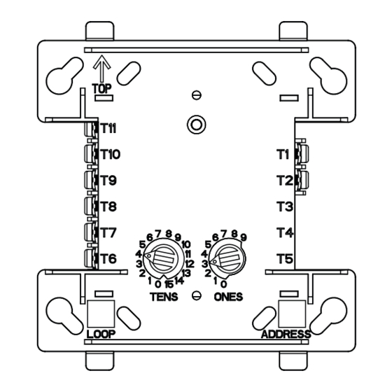
FIGURE 1A. CONTROLS AND
INDICATORS:
C1059-00
Phone: 203-484-7161 Fax: 203-484-7118
www.silentknight.com
APPLICATION
Non-coded
Non-coded
Coded
Non-coded
Non-coded
Non-coded
Non-coded
Non-coded
FIGURE 1B. JUMPER LOCATION:
J1
C0910-00
I56-3436-004
04-12
Advertisement

Related Manuals for Honeywell SILENT KNIGHT SK-Control


Summary of Contents for Honeywell SILENT KNIGHT SK-Control
- Page 1 INSTALLATION AND MAINTENANCE INSTRUCTIONS INSTALLATION AND MAINTENANCE INSTRUCTIONS SK-Control 12 Clintonville Road, Northford, CT 06472-1610 Phone: 203-484-7161 Fax: 203-484-7118 Supervised Control Module www.silentknight.com SPECIFICATIONS Normal Operating Voltage: 15 to 32 VDC Maximum Current Draw: 6.5 mA (LED on) Average Operating Current: 375 µA (LED flashing - in group poll mode) 350 µA (LED flashing - in direct poll mode) 485 µA Max.
- Page 2 Silent Knight ® and Honeywell ® are registered trademarks of Honeywell International, Inc. I56-3436-004 ©2017 Honeywell. 04-12...
Need help?
Do you have a question about the SILENT KNIGHT SK-Control and is the answer not in the manual?
Questions and answers